City, University of London Institutional Repository
Citation
:
Marchi, A., Nouri, J. M., Yan, Y. & Arcoumanis, C. (2010). Spray stability of outwards opening pintle injectors for stratified direct injection spark ignition engine operation. International Journal of Engine Research, 11(6), pp. 413-437. doi:10.1243/14680874JER605
This is the accepted version of the paper.
This version of the publication may differ from the final published
version.
Permanent repository link:
http://openaccess.city.ac.uk/6075/Link to published version
:
http://dx.doi.org/10.1243/14680874JER605Copyright and reuse:
City Research Online aims to make research
outputs of City, University of London available to a wider audience.
Copyright and Moral Rights remain with the author(s) and/or copyright
holders. URLs from City Research Online may be freely distributed and
linked to.
Spray characteristics of outward opening injectors in a DISI optical engine
A Marchi, J M Nouri*, Y Yan and C. Arcoumanis
Centre for Energy and the Environment
City University London, School of Engineering and Mathematical Sciences
Northampton Square, London, EC1V OHB, UK
*corresponding authors: [email protected]
Abstract: The spray characteristics of three prototype piezo-electric pintle-type injectors was investigated
under different operating conditions in an optical engine equipped with direct injection system and designed for spray-guided combustion concept. The pintle-type outward opening has the potential to overcome many of the typical problems related to spray-guided injection. Its hollow cone spray presents a better air utilization than the multi-hole with good penetration performance during early injection and a negligible dependence of the spray angle from the backpressure; the latter is essential for spray-guided approach to be successful as it fully depends on spray stability. The three prototype injectors are designed with different nozzle exit geometries for optimisation of the injectors for the most stable spray at all engine conditions.
The emeringing fuel sprays, for single and double injection, were visualised using Mie scattering and a high speed CCD camera. The injectors’ performance were assessed by constructing mean and RMS images at different operating conditions of injection pressures, back pressure, injector needle lift, and engine speed. From these images a through angle analysis were performed by comparing the mean, standard deviation, maximum and minimum spray cone angle at different conditions; the spray stability could be quantified by analysising the mean and RMS images and mean and RMS spray cone angles. Overall, the classification of the three prototypes has shown that the Inward Seal Band positive step design produces the most robust spray angle, which is ideally suited for stratified fuel mixture formation in spray-guided configurations for DISI engines.
Keywords: DISI optical engine, piezo injector, outward opening, spray imaging
1 INTRODUCTION
The direct injection of gasoline within the engine cylinder is regarded as one of the main strategies to improve the combustion efficiency of spark ignition engines and represent a promising approach to fulfill the main target for the improvement of fuel economy and the reduction of CO2 emissions to a stringent target of 120g/km by 2012 [1, 2]. To achieve this target, high compression ratio is applied together with a lean combustion strategy during part load operation (late compression stroke) with stratified charge. The success of such strategy depends on a suitable injector that can produce stable spray for both full load and part load operations in particular if the spray-guided approach is adopted for low load operation [3]. A double injection strategy can also improve transition between part load and full load, by injecting partially during the intake and partially during the compression stroke. The use of double injection during part load, steady state operation is beneficial for soot emissions reduction, and can provide improved fuel economy at the transition between stratified and homogeneous mode, at low engine speeds; these strategies may also be used to avoid engine knock or to extend the knock limit and enhancing torque at full load.
The outward opening injection is one of the new promising injector that was developed to be used in direct injection spark ignition (DISI) spray-guided system. The spray structure from this type of injectors
2
negligible. This string-type structure originating at the nozzle exit had been observed by [11-13] who argued that string formation could be the result of the interaction between the airflow and the injected liquid annular film. The source of this string-type spray structure was further investigated experimental by [14-15] and showed the presence of a very complex flow upstream of nozzle seat. The magnified in-nozzle flow visualisation complex two-phase flow with air entrained bubble trapped downstream of the nozzle seat initiating the formation of string (filament-type) spray structure as it emerges from the nozzle. Overall, the experimental evidences suggested that the formation of the string-type spray structure produced by such nozzles could be attributed to the presence of complex two-phase flow inside the nozzle and the balance between the aerodynamics force and surface tension outside the nozzle all of which may affect the stability of the exiting spray jet. The type of in-nozzle two-phase flow was the result of either the initiation and development of cavitation or due to partial occupancy of the expanding annular needle seat flow passage, leading to air entrainment and flow separation just upstream of the nozzle exit or even both depending on different operating conditions and, in particular, the exit nozzle geometry.
As mentioned earlier, for a spray-guided combustion system, it is crucial to have stable sprays with minimum variation not only at the same cylinder conditions but also under different engine loads and speeds. Since in spray-guided system the spark plug and injector are located close to each other and if the spray moves away from the spark plug location engine misfire may occur. Designing an injector to produce a spray with specified characteristics is always a very time consuming task, and in most of the cases, it is based on extensive measurements and different trials due to the lack of information about the flow conditions at the nozzle exit and the atomisation process. This paper is therefore designed to investigate the spray characteristics of the different outward opening Inward Seal Band injectors mounted in an optical engine equipped with direct injection system. The present injectors are the latest design for the application of DISI engines after the swirl type and multi-hole injectors. In this study, three prototype piezo-electric injectors were analysed by visualising the spray injections through the transparent cylinder wall of the optical engine at different operating conditions using a high speed CCD camera; the main difference between them is the geometry of the exit nozzle as will be shown later. The parameters, that were investigated, were injection pressures, backpressure, injector needle lift and engine speed. Double injections were also tested under similar injection conditions as those with the single injection test cases. The analysis aimed to compare the spray characteristics in terms of spray pattern, spray cone angle and its stability. The post processing was based on the statistical computation of many set of images under different operating conditions. The object of the assessment consisted of the comparison of average and standard deviation images obtained from automated graphic processing and to identify the most
stable injector.
2 EXPERIMENTAL SET UP
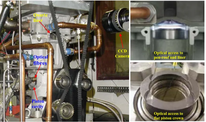
The spray visualization has been performed using a Ricardo-Hydra optical engine provided by BMW AG as shown in Figure 1. The combustion chamber is a 4-valve pent-roof with a bore diameter and stroke length of 84 mm, a stroke length of 90 mm and a compression ration of 10.8. The optical cylinder was characterised by a short portion of transparent cylinder liner (25 mm) made of quartz with full optical access from all four sides of the cylinder and an extension of the transparent window above the gasket exposing the front and back sides of the pent-roof. The piston head is equipped with a quartz window, which gives an additional optical access for visualization or lighting. In order to direct the optical path toward the combustion chamber through the piston crown window, a mirror is placed at the bottom of the piston cavity inclined at 45º with respect to cylinder axis. The Hydra engine cylinder head arrangement is shown in Figure 2 and presents the injector and spark plug positions which are alligned on the plane of symmetry of the flame deck with the injector located on the centre of the chamber and the spark plug towards the exhaust valves; a typical narrow spacing suitable for spray-guided combustion.
Spray visualization was performed in the optical engine, shown in Figure 1, and the best optical set-up was chosen to achieve good image definition and the most meaningful point of observation. A fast 12bit CCD camera with a resolution of 1024x1240 pixels and low readout noise was employed to obtain spray images in the optical engine illuminated by a xenon flash light and two flexible optical fibres; the camera was equipped with a Nikkor telescopic zoom lens (75-300mm 1/4.5-5.6). A driver control system was used to trigger the injector and signal process unit. The same TTL pulse from control system was used to trigger both the camera and the xenon light at specified time before end of injection (EOI) which is referenced from the rising edge of the injection signal to the injector driver during activating cycle.
2.1 Experimental Strategy
The current investigation is focused on the analysis of spray stability observed in the above-described engine by assessing the spray images of different sets of injectors at different operating conditions through statistical analysis of processed data, in particular, the variation of spray angle. After synchronising the end of the injection (EOI) with the camera trigger, the image quality was adjusted in order to obtain the required image definition and finally it was possible to proceed with the image acquisition at the actual operating condition.
The main part of the investigation consisted of 31 single injection cases and 31 double injection cases each of which comprised of a set of 64 images. Additionally for double injection mode at high cylinder pressure a set of 64 images were taken for both primary and secondary EOI, whereas for the other double injection cases only images at EOI of first (primary) injection were taken.
3
statistical mean and RMS images were obtained by averaging and calculating the standard devieation (STD) of the gray level value of each pixel out of all 64 images. The mean image gives a representative view of the spray general behaviour and shows the location of the main strings from which the repeatability of spray-to-spray behaviour can be deduced. The RMS image shows the variability of the spray pattern and it can be used to identify the degree of the spray stability. More
specifically the RMS graphic operation produces an image where the brighter areas represent higher fluctuation in the grey level and therefore more spray variation or displacement (spray-to-spray variation). Since one of the aims of this investigation is the analysis of the flapping behaviour of the spray, the RMS image gives a good qualitative measure of the repeatability of the spray shape and thus of the entity of the spray flapping.
[image:4.595.90.493.199.439.2]
Fig. 1 Model Hydra optical engine with limited quartz window.
Fig. 2 Flame deck configuration of Hydra engine.
2.2 Operating conditions
The parameters defining the operating condition of each case are:
• Injector model. Three injector prototypes with
[image:4.595.62.516.673.761.2]different needle geometry were tested to establish the effect of the step between cartridge internal diameter and needle external diameter. The step is evident when the injector is closed and it consists in a positive or negative edge between needle and cartridge rims. The injector with diameter of the needle larger than the cartridge is refered to as positive step Inward Seal Band injector (+ISB) while the vice versa is negative step Inward Seal Band injector (-ISB) as can be seen in Figure 3. The third injector, named as standard inward seal bend (SSB), presents needle diameter of the same size as the cartridge and therefore with no step when the injector is close.
Fig. 3 Injector geometries: Inward Seal Band positive step (+ISB), Inward Seal Band negative step
(-ISB) and Standard Seal Band No step (SSB).
Quartz liner
CCD
Camera
Piston cavity
Optical
fibres
Optical access to pen-roof and liner
• Backpressure. Three different in-cylinder
backpressures, Pb, were considered. As the spray
behaviour at homogenous condition (full load) is as important as that of late injection (part load) then three most representative conditions were chosen at an early intake stroke phase (~180°BTDC) and two late compression stroke of 25° BTDC and 10°; the corresponding chamber pressures are 1, 10 and 16bars.
• Injection rail pressure. Two injection pressures, Pi,
(100bar and 200bar) were considered to investigate the effect of rail pressure on the spray stability and on the penetration.
• Needle lift. The piezo injector presents the
characteristic of a variable maximum lift, which can be adjusted by the activation of the injector piezo bodies. To investigate the effect of the maximum lift on the penetration and spray angle two lifts were analysed: a lift of ~36μm (full piezo body activation:1111) and a lift
~19μm (minimum piezo body activation:0000).
• Engine speed. The engine speed has a strong effect on
the in-cylinder air motion. Tumble and swirl are strongly affecting the spray stability and therefore it was decided to observe the spray behaviour for two engine speeds of 1000 rpm and 2000 rpm. Due to vibrational and thermal problems on the optical engine, it was not possible to push the engine to higher speeds than 2000 rpm.
• First/second injection duration. For double injection,
the effect of the first injection duration may influence the intensity of the wakes and the in-cylinder air motion, which could consequently affect the stability of the second injection. Two injection durations (t1 = 0.2ms, 0.5ms) were chosen and compared at different operating conditions.
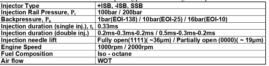
[image:5.595.58.496.313.421.2]All the aforementioned operating conditions are summarised in Table 1 below.
Table 1 Operating parameters and Engine set up.
Injector Type +ISB, -ISB, SSB Injection Rail Pressure, Pi 100bar / 200bar
Backpressure, Pb 1bar(EOI-138) / 10bar(EOI-25) / 16bar(EOI-10)
Injection duration (single inj.), ti 0.33ms
Injection duration (double inj.) 0.2ms-0.3ms-0.2ms / 0.5ms-0.3ms-0.2ms
Injection needle lift Fully open(1111)( ~36μm) / Partially open (0000)(~ 19μm) Engine Speed 1000rpm / 2000rpm
Fuel Composition Iso - octane
Air flow WOT
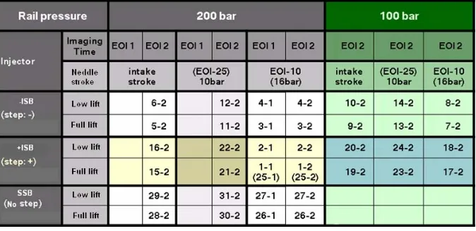
For single injection the duration, ti, was fixed at 0.33 ms
for all the 31 cases whereas the remaining parameters were varied case by case according to Table 2. In order to assess the repeatability of the tests after long periods
of running and changing parameters, the 25th case was set equal to the first case and a comparison was made as a refrence case to chack the similarity.
Table 2 Test conditions for single injection investigation. (First set of results).
After the single injection imaging was completed, all the cases were repeated for the double injection mode by triggering the camera at the end of the first injection except for cases 1 to 4 where both end-of-injections were taken . The test conditions and parameters for double injection are summarised in Table 3. The imaging signal
[image:5.595.125.470.530.675.2]5
Table 3 Test conditions for double injection investigation. (case No. – injection No.)
2.3 Spray angle analysis
For the spray angle analysis, the contour was first determined by fixing a threshold to the pixel level variation as depicted in Figure 4. The spray angle calculation was defined between injector tip and a fixed axial distance. For each individual spray image, the
[image:6.595.55.293.352.644.2]angle between the axis and a segment on either side of the spray (covering the spray contour) was measured starting from the injector exit. The overall spray angle was defined as the summation of the angle between the two segments on either side and the spray axis. The overall angle measurements were performed for all cases and an example is shown in Figure 4.
Fig. 4 Image processing procedure.
Fig. 5 Statistical spray angle values obtained from
a set of 64 images.
In order to analyse and compare the spray angle data between different operating conditions the more representative statistical parameters were summarised in plots as shown in Figure 5 reporting the mean, ± STD that represents the deviation from the mean value and maximum and minimum values of the image. For conciseness, the following comparisons will only report the statistical plots which give all the elements for the study of spray angle stability by the observation of the STD and of the range of spray angle variation given by maximum and minimum angles.
3 RESULTS AND DISCUSSIONS 3.1 Single injection
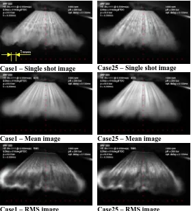
As mentioned in the previous section, first a reference testing was carried out by comparing images taken at the beginning of the test and those taken at different time but at the same operating conditions, for example, at the end when all other testings were fisnished. The collected sets of images were then compared in order to establish the spray repeatability and to check the equipments setting after all the changes made for the image acquisitions. Figure 6 presents such comparison betweens cases 1 and 25, which show good degree of similarity between the single shot (instantaneous), mean and RMS images. Note that the scale is shown on all images by the red cross and the distance between two consequtive cross is 1mm as indicated on one of the image.. It can be seen from the mean images, averaged over 64 images, that the strings are very well defined and similar to those of the single image suggesting a good and strong repeatability of the string pattern. This is not the same for the circumferential undulations, nearer to the tip of the spray, conferring a curly aspect to the strings and is more visible in the spray of case 1; this behaviour resembles the Kelvin-Helmholtz instability.
Case1 – Single shot image Case25 – Single shot image
Case1 – Mean image Case25 – Mean image
Case1 – RMS image Case25 – RMS image
Fig. 6 Reference comparison of single shot, mean and RMS spray images for the same operating
condition. (Case 1 vs Case 25)
[image:7.595.162.441.82.389.2]Case 1 Case 25
Fig. 7 Statistical angle comparison for the same operating condition. (Case 1 and Case 25)
The RMS images show brighter areas in the recirculation zone around the tip of the spray for both cases indicating larger fluctuations. This is expected that as the fuel droplets in these regions have much smaller momentum and therefore more vunrabled to the air motion inside the cylinder; in general, the bright contour seems equally distributed in both images. Finally, the angles statistic, shown in Figure 7, exhabits good match between the mean angles of 87º for both cases and the RMS is about 1º in both cases. The max and min values must be taken with care and not to be overestated since they represent the picks of the set of images and they may easily be affected by isolated events. Similar results were obtained at other operating conditions, which give a measure of the repeatability and comparability of results in this study and a good reference for the image acquisition. The first comparison between the three prototypes,
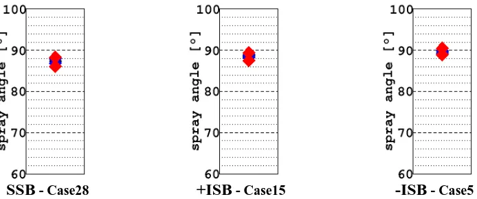
described in the previous section, was made at intake stroke phase and therefore at ambient cylinder pressure; other operating conditions were kept the same at full needle lift, engine speed of 1000 rpm and injection pressure of 200 bar. The comparison of the images shows remarkable resemblance between the single and mean images for all three injectors and that their overall spray cone angles looks similar as can be seen in Figure 8. The only noticeable difference is the position of the strings with differenct injectors as would be expected. The angle analysis, presented in Figure 9, quatifies the cone angle observation expressed above and shows similar mean cone angle for all three prototypes varying from 87º to 90º as it is evident from the presented data. The RMS is very small (~1º) which means that the spray at this operating condition is very stable for all the three injector geometries.
SSB
Case28 – Single shot image
+ISB
Case15 – Single shot image
-ISB
Case5 – Single shot image
Case28 – Mean image Case15 – Mean image Case5 – Mean image
[image:8.595.90.515.69.438.2] [image:8.595.127.474.469.614.2]Case28 – RMS image Case15 – RMS image Case5 – RMS image
Fig. 8 Image comparison for three different injector prototypes: Full needle lift, 1000rpm, Pb=1.1bar, Pi=200bar.
SSB
- Case28+ISB
- Case15-ISB
- Case5Fig. 9 Angle comparison for three different injector prototypes: Full needle lift, 1000rpm, Pb=1.1bar,
Pi=200bar.
Since the comparison between all images (single, mean and RMS) are similar to what presented in Figures 6 and 8 and at the same time they would take too much space, it was decided to present only the mean images and angle analysis of the spray for consideration of the following parameters.
The following comparison, Figure 10, is performed at a much higher backpressure than the previous case by injecting fuel during late compression stroke. The images were taken at 25° BTDC (in-cylinder pressure of 10.9bar) and show an expected decrease in penetration
8
left seem slightly asymmetrical and projected toward the sparkplug. This effect was absent in the previous comparison at ambient condition probably due to the milder effect of tumble during induction and smaller droplets momentum during the late compression. The mean images show clearly the presence of strings structure suggesting good degree of spray repeatability;
again the sharpness of the strings are less evident with SSB injector. The angle analysis, presented in Figure 10(a), confirms the finding of spray images with a higher angle variation of ±3° for the SSB injector and an overall cone angle of 77.5°, which is smaller angle than positive and negative step injectors.
SSB (Case 30) +ISB (Case 21) -ISB (Case11)
(a) Mean image comparison
(b) Angle analysis
Fig. 10 Comparison between the three different injectors at full needle lift, 1000rpm, Pb=10.9bar,
Pi=200bar: (a) Mean image comparison; (b) Angle analysis.
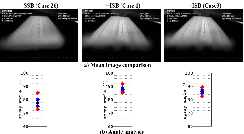
SSB (Case 26) +ISB (Case 1) -ISB (Case3)
(a) Mean image comparison
[image:9.595.87.509.164.391.2]
(b) Angle analysis
Fig. 11 Comparison between the three different injectors at full needle lift, 1000rpm, Pb=16.6bar,
Pi=200bar: (a) Mean image comparison; (b) Angle analysis.
The comparison at the highest backpressure was performed by delaying the end of injection (EOI) just 10° before TDC. This phase is extremely important as it is adopted at part load during stratified charge operation and it represents one of the main challenges of the GDI concept. The results are presented in Figure 11 for all three prototypes and a further decrease in penetration is
[image:9.595.84.506.427.659.2]9
with a smaller cone angle than the two ISB injectors. The angle analysis, Figure 11(b), confirms the points observed in the images especially for SSB injector, showing a large variation in spray cone angles with a STD of ±2.5° and a much smaller cone angle (78°) than the other ISB injectors by up to 10°. For all three tested backpressures, the higher standard deviation of the SSB is an indication of higher spray instability with this injector, associated with the higher backpressures, and not suitable for spray-guiaded configuration compare to other two prototypes.
The comparison presented in Figure 12 differs from the previous one, Figure 11, by setting the needle lift to minimum (0000) (~19μm). The most evident variation appears to be the spray penetrations, which are up to 35% less than those at maximum lift and that the spray density are also less than the corresponding sprays at maximum lift as would be expected since the injected fuelm is less. In addition, the three sprays structure and shape look now more different to one another. For instance, the –ISB in case4 presents the most symmetrical shape, the +ISB in case2 shows the sharper string pattern but with a less dense spray, and finally the SSB in case27 is characterised by a blurry denser spray structure. The pronounced asymmetry with the SSB seems to be mainly caused by lack of homogeneity in the needle sealing rather than for airflow motion. The density of the spray is judged qualitatively by the intensty of the scattered light. The RMS images, not
shown here, reveal an an overall increase in spray instability with all three injectore and this is more pronounced with +ISB which expose a clear bright rim all around the spray profile. The comparison of the angle analysis confirms above observation with large varieation of spray cone angle of up to ±2° for SSB and –ISB injectors and up to ±3° for the +ISB. The comparisons of the STD results with the previous maximum lift conditions show an increased angle variation for both ISB injectors by up to 3 times while almost unvaried for the SSB injector. Both –ISB and SSB present the same mean angle observed in the previous comparison whereas the +ISB shows a drop of about 10°.
Overall it seems that the needle lift reduction produces a detrimental effect on the spray stability which is specially felt by SSB and + ISB whereas the negative step Standard Seal Band is more robust and insensitive to the needle lift set up.
3.1.1 Influence of engine speed
The engine speed has a great influence on in-cylinder charged motion, tumbling and turbulence. These, in turn, will affect the spray stability and its dispression. To observe the effect of the engine speed on the spray angle shape and its stability several tests were performed at engine speeds of 1000 and 2000 rpm at full and low lifts for the +ISB injector. The results are presented in Figures 13 and 14 and show comparison of Case1 and Case 2 at different engine speed.
SSB (Case27) +ISB (Case2) -ISB (Case4)
(a) Mean image comparison
(b) Angle analysis
Fig. 12 Comparison between the three different injectors at low needle lift, 1000rpm, Pb=16.6bar,
Pi=200bar: (a) Mean image comparison; (b) Angle analysis.
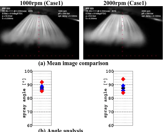
At full lift (~36μm), Figure 13, the comparison of Case1 between engine speeds of 1000rpm and 2000rpm shows that the spray is pushed a bit further towards the sparkplug by the tumbling motion at higher speed; this is more evident when looking at the spray tip region on the right hand side. The spray fluctuation, from RMS images, of Case1_2000rpm shows also a higher variation in the recirculation area and suggests an increase of
10
to ±1° at lower speed due to increased air motion and turbulence. These tests have been carried out with and without the presence of spark plug and the results were
the same both in mean and STD angles suggesting that the effect of the spark plug protrusion on the in-cylinder air motion is very small and negligible.
1000rpm (Case1) 2000rpm (Case1)
(a) Mean image comparison
(b) Angle analysis
Fig. 13 Effect of engine speed on spray from +ISB injector at full needle lift, Pb=16.6bar, Pi=200bar:
(a) Mean image comparison; (b) Angle analysis.
1000rpm (Case2) 2000rpm (Case2)
(a) Mean image comparison
(b) Angle analysis
Fig. 14 Effect of engine speed on spray from +ISB injector at low needle lift, Pb=16.6bar, Pi=200bar:
(a) Mean image comparison; (b) Angle analysis.
At lower needle lift position (~19μm), Figure 14, the comparison between the two engine speeds shows similar effects to those of the previous case study (full lift, Figure 13). The observed shift of the spray toward the spark plug at the full lift case is less evident probably due to the smaller penetration of the spray. However, the RMS image at higher engine speed presents a very bright boundary not only in the recirculation areas but also around the tip of the spray suggesting higher spray angle fluctuation and penetration variability. The former can be quantified from the angle analysis, Figure 14(b),
with STD values of ±3.1° and ±2.5° for 2000rpm and 1000rpm, respectively. The corresponding values at full lift were ±1.75° and ±1° which suggest an overall increase in spray instability at the low lift. From the images at higher engine speed, it can be observed that the spray tends to become wider and this is in accord to mean cone angle value, which is around 85° and higher than that at lower speed, by 6°.
3.1.2 Influence of backpressure
[image:11.595.156.433.119.344.2] [image:11.595.159.438.383.607.2]11
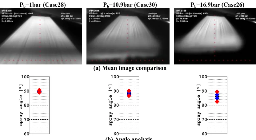
injection mode based on the engine load, which implies injections at different cylinder pressures. It is important to have an injector capable of providing stable sprays at different loads with the potential to self-adjustment of its penetration as the piston advances in order to avoid wall impingement which otherwise would cause unburned hydrocarbon and increase emissions. The following comparison presented in Figures 15, 16 and 17 shows the effect of three different backpressures (1bar, 10.9bar, 16.6bar) for SSB, +ISB and –ISB injector prototypes, respectively, at full needle lift, an engine speed of 1000rpm and an injection pressure of 200bar.
For SSB prototype, Figure 15, the immediate effect produced by backpressure increase is evidently the drop in penetration, which is caused by the increased in-cylinder gas density and the consequent increase of drag resistence. The spray shape seems to be also affected by the backpressure that affects the spray axial-symmetry due to the enhanced effect of the air motion. In fact, the increase in density of the surrounding gas amplifies the drag forces acting on the droplets causing loss of momentum and therefore they become more susceptible to the tumbling gas motion that pushes the spray droplets toward the spark plug. By its nature, the tumble is an unstable phenomenon and consequently its effect is
transmitted to the spray stability, which decreases with the increase of the backpressure. From the RMS images at ambient pressure, not presented here, it could be observed that the whole spray profile was found to have uniform dark gray-scale with very sharp and straight boundary suggesting a very stable spray. At 10.9 bar back pressure the spray-profile denotes a brighter profile in the recirculation areas as well as around the spray tip indicating spray fluctuation; This instability is furthere amplified at higher backpressure of 16.6bar.
A very clear trend showing the effect of the backpressure is shown in the following angle analysis, Figure 15(b), where a small and gradual collapse in the mean cone angle can be seen; from 89.7° at ambient pressure down to 88° at Pb=10.9bar and down to 86° at Pb=16.6bar, giving rise to
an overall reduction of 4.2%. This suggests a small increase in pressure force on the outer surface of the cone spray, which may be due to the stronger effect of the outer wakes against the inner wakes. Such a result becomes more intense at higher gas density due to the amplification of the drag. It can be also observed a consistent increase of the STD values that indicates an objective increase of spray instability with the cylinder pressure which confirms the visual results of spray images; the STD values changes from ±0.3° at ambient pressure to ±1.5° at Pb=16.6bar.
Pb=1bar (Case28) Pb=10.9bar (Case30)
(a) Mean image comparison
Pb=16.9bar (Case26)
(b) Angle analysis
Fig. 15 Effect of cylinder back pressure on spray from SSB injector at full needle lift, 1000rpm,
Pi=200bar: (a) Mean image comparison; (b) Angle analysis.
From the above discussion and the results presented in Figures 8, 9 and 10, it can be conclused that all three protypes are very stable under ambient back pressure, but at higher backpressure during the compression stroke, the SSB becomes very unstable compare the other two ISB prototypes and therefore not suitable for spray-guided combustion. Overall, the two ISB injectors are proved to be the most stable prototypes against backpressure with the positive step having the upper edge.
In addition, similar tests to those mentioned above were performed for the two stable ISB prototypes to analyse the backpressure effect but at a different injection
[image:12.595.86.502.369.596.2]12
lower injection pressure; this makes the spray more susceptible by the in-cylinder air motion.
3.1.3 Influence of needle Lift
[image:13.595.152.435.371.678.2]In order to avoid impingement it is necessary to have the full control of the spray penetration especially at part load when the piston is very close to the TDC. One of the main advantages of the piezo type injectors under investigation is the possibility to vary the maximum lift according the activation of the piezo body, which set in motion the pintle. Here, the comparison has been made between the two extreme cases of maximum and minimum full lifts to characterise the spray stability and are referred to as full lift (~36μm with deriver set at 1111) and low lift (~19μm with deriver set at 0000), respectively. The results are presented in Fugures 16 and 17, which compares the mean spray images and angle analysis for the three prototypes.
Figure 16 compares the mean spray images at two extreme needle lifts and shows that the first and most important difference is the significant penetration difference between the two needle lift positions with all three injectors with almost the same level of reduction in penetration of around 33%. This implies that the needle lift position can play a major role in controlling the spray
penetration; it is interesting to notice that the reduction in spray pentration is almost the same for three prototypes suggesting that the exit nozzle changes had little enfluence on the spray penetration.
From the results it is clear that the +ISB and –ISB injectors exhibit a good degree of spray symmetry at full lift, but not so with the SSB injector where it shows a lack of symmetry with the spray cone tilting towards the sparkplug which, as argued before, can be attributed to increased drag of higher gas density. At lower needle lift, the spray asymmetry effect seems to be amplified especially in the case of SSB injector (Case27), and to some extend for +ISB injector, where the penetrations of the left and right sides of the spray cone are clearly very different. It was argued before that this spray asymmetry between high and low lifts can be due to tumbling air motion, but it may also be because the emerging flow is more sensitive to cross section area variation at the lower lift. Needle imperfections or non-uniformity in the opening phase creates an uneven cross section exit and the relative geometrical error (irregularity/lift ratio) is much higher when the exit cross section area is smaller. Therefore, the emerging flow will be more sensitive to geometrical exit imperfections at low lift than at full lift.
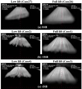
Low lift (Case27) Full lift (Case26)
Low lift (Case2) Full lift (Case1)
Low lift (Case4) Full lift (Case3)
Fig. 16 Mean spray image comparison of three prototype injectors at low (left column) and full (right column)
needle lifts, Pb=16.6bar, 1000rpm, Pi=200bar: (a) SSB prototype; (b) +ISB prototype; (b) -ISB prototype.
Another usefull observation is that the spray recirculation area is much more pronounced at full lift whereas at low lift it is almost absent. Despite useful penetration control at lower lift, but that may represent a draw back as it implies smaller ignitable fuel mixture
areas at lower lift. Overall, the -ISB prototype exhibits a better injector in terms of spray symmetry at low lift than the other two prototypes; SSB prototype again proved to be not suitable at all needle lifts.
(a) SSB
(b) +ISB
SSB (low lift)
Case27
SSB (full lift)
Case26
+ISB (low lift)
Case2
+ISB (full lift)
Case1
-ISB (low lift)
Case4
-ISB (full lift)
Case3 Fig. 17 Angle comparisons for different needle lifts for the three injector prototypes at 1000rpm,
Pi=200bar, Pb=16.6bar.
[image:14.595.93.509.84.244.2]The angle analysis of spary images in Figure 16 has been carried out and a summary with respect to needle lifts is presented in Figure 17. of the presented the results show that the mean cone angle with SSB decreases at low need lift even though no difference in spray variation can be seen from the STD. A much large decrease in cone angle is experienced by the +ISB prototype with a drop of up to 10º at low lift compared to 3º with SSB injector. The STD at low lift is ±2.5º and similar to that of SSB while at full lift it is much smaller (±1º) and more stable spray. Unlike the SSB and +ISB prototypes, the negative step (-ISB) exhibit the most stable injector in terms of mean cone angle with a drop of only 1º at low lift while its STD values are similar to that of +ISB at both lifts. Overall, the SSB prototype has performed the poorest characteristics in terms spray stability and, in general, it presents a relatively low mean angle which slightly increases at full lift. The -ISB presents a much higher mean angle than the SSB with much reduced STD at both lifts particularly at full lift. The +ISB injector exhibits an intermediate behaviour between SSB and -ISB. At low lift the mean angle is as low as for the SSB with similar STD whereas at full lift the mean angle raise of about 10º comparable to that of –ISB with a similar STD.
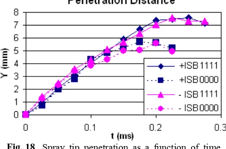
Fig. 18 Spray tip penetration as a function of time
after SOI at full and low needle lifts for ISB injectors: 1000rpm, Pi=200bar, Pb=16.6bar.
The variation of spray tip penetration as a function of time after start of injection is presented in Figure 18 and
shows that spray needle lift has almost no effect on penetration distance at the initial 0.1ms of injection for both injector types. Bryond that, the rate of increase in penetration slows down with both injectors and more so with the low lift cases until the penetrations become uniform at 0.175ms with a value of around 5.5mm for low lifts and 7.5mm at 0.2ms for full lift. The overall penetration distance is less than 8 mm for both ISB injectors at full lift when injected at EOI-10 BTDC (16.6 bar backpressure), which means low risk of fuel impingement on the piston crown. The maximum difference in penetration has shown to be of order of 36% between the two lift settings, which gives a high flexibility for the penetration control at part load. The results also suggest that fuel droplets are undergoing sever atomisation processes and more effective evaporation as the fuel emerges from nozzle so that by mid-injection period the droplets become small enough to loss most of their momentum and become almost suspended. This gives a very good indication of superior performance of this type of injectors which make them quite suitable for spray-guided combustion and have advantage over the multi-hole injectors.
3.2 Double injection
The capabilities of modern control systems allow complex strategies for mixture formation and control. Split injection can be achieved with the use of appropriate electronic and common rail systems. A double injection strategy can improve transition between part load and full load, by injecting partially during the intake and partially during the compression stroke. With this injection strategy, a fraction of the fuel is injected during the intake stroke and the remaining fraction is injected just prior to the spark, creating a homogeneous lean mixture in the chamber and a locally rich mixture at the area around the spark gap. The use of double injection during part load, steady state operation is beneficial for soot emissions reduction, and can provide improved fuel economy at the transition area between stratified and homogeneous mode, at low engine speeds. Split injection strategies may also be used to avoid engine knock or to extend the knock limit and enhancing torque at full load.
[image:14.595.52.282.571.723.2]14
smaller pulse widths. This may decrease spray quality and cause unstable fuel delivery for GDI injectors other than piezoelectric as was shown by [16 and 17]. This happens because common GDI injectors’ pulse widths are longer to cover for slow needle opening and closing ramps. Piezoelectric injectors, on the other hand, can operate with accuracy in much shorter pulses due to their rapid actuation. The limited following tests were carried
out to characterise the spray patterns and cone angle analysis for double injection with the three prototypes at different conditions as listed in Table 3; particular attendion was given to second injection event of double injection since it might have been influenced by the wake of the first injection event. Results are presented maily for a very late injection timing, (10 BTDC:
Pb=
16.6bar), approprieate for Spray-guided combustion.EOI2 Double inj. (Case25-2) EOI2 Double inj. (Case1-2) EOI Single inj. (Case1)
(a) Mean image comparison
[image:15.595.84.506.178.403.2]
(b) Angle analysis
Fig. 19 Reference comparison of second injection event from +ISB injector for different test cases but at the same
EOI, full needle lift, 1000rpm, Pi=200bar, Pb=16.6bar: (a) Mean image comparison; (b) Angle analysis.
EOI1 Double inj. (Case1-1) EOI2 Double inj. (Case1-2) EOI Single inj. (Case1)
(a) Mean image comparison
(b) Angle analysis
Fig. 20 Comparison between the EOI of double injection (1st and 2nd injection events) and single
injection for +ISB injector at full needle lift, Pb=16.6bar, 1000rpm, Pi=200bar: (a) Mean image
comparison; (b) Angle analysis.
3.2.1 Comparison of reference
With reference to Figure 19, the following set of images assesses the repeatability of the results in terms of the spray pattern and cone angle. The images are from second injection event of double injection and were
[image:15.595.80.508.441.669.2]15
images of the spray at the same EOI and operating conditions do not show any noticeable difference especially between the two double injection cases (Case25-2 and Case1-2). The perceptible difference in penetration between double and single injections is very small and may be associated with the limits on the accuracy of pulse synchronisation due to the different signal setting between single and double injection. Nevertheless, the two double injection samples are practically identical proving the good repeatability of the test condition. These are also evident from the angle analysis data which does not show much differences in STD for all of the cases with values up to ±1°, and even the mean angles do not reveal any significant difference with values between 89° and 90°.
The comparison between the first and second injection
event shows a very good resemblance between the spray structures as can be seem in Figure 20(a) between EOI1 and EOI2 mean spray images. Nevertheless, the spray recirculation in the second injection looks slightly disturbed. In fact, the first injection may influence the in-cylinder air motion, which in turns affects the out coming second injection. More specifically, the recirculating (wake) ring and surrounding air velocity field produced by the first injection may interact with the second injection. The angle analysis, Figure 20(b), also identifies this small differenrce between the first (EOI1) and second (EOI2) injection events and shows a small increase in mean cone angle by 1.3°. As it is evident that the STD values between the two injection events are very similar, which is also equal to the reference single injection of Case1.
EOI1 Full lift (Case1-1) EOI1 Low lift (Case2-1) EOI2 Low lift(Case2-2)
(a) Mean image comparison
[image:16.595.87.509.267.493.2]
(b) Angle analysis
Fig. 21 Effect of needle lift on double injection sprays for +ISB injector and at different EOIs,
Pb=16.6bar, 1000rpm, Pi=200bar: (a) Mean image comparison; (b) Angle analysis.
The effect of needle lift was considered next and a sample of results are presented in Figure 21. In general, like with single injection, the penetration was much less at low lift, and was more so with the penetration of the 2nd injection event. At low lift, the 1st injection (Case2-1)
seems considerably degraded presenting a lower mean cone angle (2°) and higher angle variation (±1.5°) lower than Case1-1 at full lift (±1°). This effect is far worth with the 2nd injection event and presents a massive mean
cone angle drop (15°) and acosiderable increase in STD (±5°) compare to those of Case1-1 at full lift. However, such a high deviation could be due to the near distance of the recirculation area (or leading edge) from the angle measuring points, which would produce a highly inconsistent evaluation of the angle statistic for such a short penetration.
3.2.2 Angle analysis overview
From single injection study for the three injectors, the SSB injector has proven to be the prototype with poorest performance in terms of mean angle stability and
spray-to-spray variation. Similar results were obtained with double injection and a summary of comparison angle analysis between single and double injections are presented below and cover all the parameters that were considered for single injection. The comparison between single and double injection for SSB at 1000rpm is shown in Figure 22 and presents similar behaviour for both injections with large spray-to-spray variation; this is much more evidence with the 2nd injection event which show a
significant difference in both STD and mean cone angle when compared to 1st injection and single injection. In
general, the SSB seems to be very sensitive to any variation of operating condition that causes a perturbation of in-cylinder air motion.
16
not better with less variation in the mean angle. No relevant difference between first and second injection can be seen with low spray variation and just a slightly
increased mean angle like that observed with the negative step prototype.
SSB
S.Inj
SSB
Dbl Inj. 1st Inj.
SSB
[image:17.595.201.398.118.284.2]Dbl Inj. 2nd Inj.
Fig. 22 Angle comparisons between single and double injection (1st and 2nd injection events) for SSB
injector at full lift, Pi=200bar, Pb=16.6bar.
_-ISB
S. Inj.
-ISB
Dbl Inj. 1st Inj.
-ISB
Dbl Inj. 2nd Inj.
+ISB
S. Inj.
+ISB
Dbl Inj. 1st Inj.
+ISB
Dbl Inj. 2nd Inj.
Fig. 23 Angle comparisons between single and double injection (1st and 2nd injection events) for ISB
injectors at full lift, Pi=200bar, Pb=16.6bar.
1.1 bar SSB
10.9 bar SSB
16.6 bar SSB
1.1 bar +ISB
10.9 bar +ISB
16.6 bar +ISB
1.1 bar -ISB
10.9 bar -ISB
16.6 bar -ISB Fig. 24 Angle comparison of single injection for three prototype injectors at different backpressures,
full needle lift, 1000rpm, Pi=200bar.
The effect of backpressure for single injection was
17
gas density and therefore of the drag forces interacting with the spray droplets. Another common factor produced by the increase in backpressure was a deterioration of the spray stability, which systematically affects all the three prototypes as can be seen in Figure 24 where a summary of the angle analysis for single injection is presented. The results show that the
prototype most affected by this phenomenon is the SSB, which presents a dramatic drop in mean angle and increase in STD. Both of the ISB show a robust behaviour against the backpressure and the positive-step prototype presents almost constant mean angle whereas the STD is comparable with negative-step prototype.
1.1 bar
SSB
10.9 bar SSB
16.6bar SSB
1.1 bar +ISB
10.9 bar +ISB
16.6 bar +ISB
1.1 bar -ISB
10.9 bar -ISB
16.6 bar -ISB Fig. 25 Angle comparison of double injection (2nd injection event) for three prototype injectors at
different backpressures, full needle lift, 1000rpm, Pi=200bar.
Similar results were obtained for double injection, and the effect of backpressure on spray of the 2nd injection
event is shown in Figure 25. The results present a slightly different behaviour to that of single injection mode, which is probably due to the overlapping effects produced by the first and second injection events. The increase in angle variation is still present to the same extend as seen for single injection, however, in double injection mode, at 16.6bar a mean angle recovery can be
observed for all three prototypes. In fact, at higher backpressure (or late injection), the effects of the wakes produced by the first injection and by the higher tumble may produce a diverging effect on the second injection angle. Again, overall, SSB prototype presents the least stable injector while ±ISB prototypes show much better stablilty, both in mean angle and STD, with the positive step having the upper edge.
[image:18.595.102.495.488.641.2]+ISB, P.Inj. 200bar +ISB,P.Inj.100bar -ISB, P.Inj.200bar -ISB,P.Inj.100bar
Fig. 26 Angle comparison of double injection (2nd injection event) for two ISB prototype injectors at
different injection pressure, full needle lift, 1000rpm, Pb=16.6bar.
The effect of injection pressure on spray of the 2nd
injection event was performed for the two ISB prototypes and the results are shown in Figure 26. With both injectors, the decrease of spray momentum at lower injection pressure resulted in loss of spray stability, which can be seen by the increase in STD angle. At 200bar injection pressure, the spray stability is the same for both injectors while at 100bar rail pressure, the –ISB prototype gives larger spray angle variation (±2°)
compare to that of +ISB (±1.5°). The small mean angle variation is within the accuracy of the analysis and it can be considered negligible for both injectors.
18
almost the same STD while the spray of the two ISB protypes became much more stable at full lift; the +ISB presents the best performance in terms of STD whereas – ISB presents the best performance in terms of mean cone
angle. In addition, at both needle lifts, it was found that an increase in engine speed would reduce the spray stability for the three injectors.
Low lift SSB
Full lift SSB
Low lift +ISB
Full lift +ISB
Low lift -ISB
[image:19.595.92.504.125.309.2]Full lift -ISB Fig. 27 Angle comparison of double injection (2nd injection event) for two ISB prototype injectors at
different needle lift, 1000rpm, Pb=16.6bar, Pi=200bar.
The effect of needle lift was also considered for double injection and the results of spray from 2nd injection event
are presented in Error! Reference source not found.27
for the three prototypes. The results show large variation in mean cone angles and STD so that at low lift the mean angles drop and STDs increase considerably and these are more pronounced with +ISB (17°; ±5.3°) and SSB (9°; ±3.4°) compare to that of –ISB (2.75°; ±2.5°). At full lift SSB performs as bad as low lift, but considerable improvement can be seen with both ISB prototypes. The
–ISB is the most stable of the three prototypes against the needle lift variation and even the mean angle does not suffer a sever drop. In general, when considering the needles lift as a parameter of analysis, the Inward Seal Band negative step shows the best performance in terms of stability in both mean and STD angles. However, for all the other parameters considered so far the the Inward Seal Band positive step has exposed the best performance of mean angle variation and of spray stability.
Table 4 Injector ranking for different tested parameters.
Prototype ranking: 1 and ++ very good; 2 and + good; 3 and – bad.
A summary of ranking of each prototype against analysed parameters is given in Table 4 from which the overall performance of each injector cab be evaluated. The score ranking for each injector is given by 1, 2 and 3 for STD angle stability and ++, +, - for mean cone angle variation; 1 and ++ are referred to very good injector, 2 and + for good injector, 3 and – for bad injector. Fron the chart it appears that the Inward Seal Band positive step is the most stable prototype whereas the Standard Seal Band exhibits the poorest performance after considering every operating conditions that was tested.
4 CONCLUSIONS
[image:19.595.79.519.470.623.2]19
operating conditions were considered and at each condition a representative set of spray images were post-processed in order to obtain statistical images of the mean and RMS and statistical data of cone angle; including mean, STD, maximum and minimum values. Below a summary of the most important findings for single and double injections is given.
4.1 Single injection
The first important observation for all injector types was the spray structure and, in particular, the string structure. The results showed a cone spray pattern with a well-defined string structure and a repeatable string pattern. For all three injector prototypes, it was observed that spray penetration was reduced considerably with increasing chamber pressure due to the resulting increase of gas density and hence the drag force against the propagating spray droplets; an increase from 1bar to 10bar produces a reduction in penetration of ~30%. The effect of engine speed on the spray characteristics was considered next, and the results showed that an increase in engine speed caused an increase of spray instability ,as would be expected, due to the augment action of the in-cylinder turbulence and stronger tumbling motion.
One of the advantages of the piezo injector is its adjustable needle lift through control of the piezo body activation. Therefore, the injector’s response was compared at full lift and at minimum needle lift with the followings conclusion:
¾ A strong decrease in spray penetration was observed when the full needle lift was reduced to minimum setting which can be used for controlling the injection process and avoiding wall impingement during part load operation.
¾ At the same time, it introduced instability in spray cone angles which is not a desirable feature. The comparison of the three prototypes revealed that the SSB exhibits the worst performance in terms of spray angle stability for both lifts and is not suitable for the spray-guided configuration during part load operation, while the Inward Seal band negative step (-ISB) has proved to be the most robust and stable configuration against needle lift variation.
4.2 Double injection
Another important flexibility offered by the piezo injector is its multiple injection operation due to its very fast response time, which can enhance the transition between part load and full load by fractioning the total fuel mass, injected during the intake and compression strokes. The main findings are listed below:
¾ In general, the spray of the first injection event was found to be similar to that of single injection but the second injection was affected by the residual flow field (wake) persisting from the first injection. More precisely, 200bar injection and low lift during the induction stroke the spray angle of the second injection was reduced and the angle instability increased. However, at the higher
cylinder pressures during the compression stroke showed a good recovery in the mean cone angle of the second injection was observed which might be because the residual flow field from the first injection was suppressed by the higher backpressure, being much less influential to the second injection spray.
¾ The comparison of the three injector prototypes identified the Standard Seal Band as the injector with the poorest performance in terms of spray stability and mean cone angle whereas both step-type injectors exhibited better performance; in particular, the positive step seemed to produce the most robust spray in stability with less spray flapping over the different operating conditions.
Overall, the classification of the three prototypes has shown that the Inward Seal band positive step produces the most robust spray angle, which is appropriate for use in stratified fuel mixtures based on the spray-guided configuration, whereas the Standard Seal band injector (no step) has shown the poorest performance for almost each parameter analysis.
ACKNOWLEDGEMENTS
The financial and technical support from BMW AG is gratefully acknowledged, in particular, to Dr Heinz for his valuable comments and support in processing of the angle analysis presented in this preport. The authors would like to thank Tom Fleming and Jim Ford for their valuable technical support during the course of this work.
REFERENCES
1 Fraidl G., Piok W., Fürhapter A., Sikinger H. and Pinter A. The potential of next generation gasoline
direct injection technologies. Associazione Tecnica dell’Automobile, 56:5-17, 2003.
2 Wirth M., Zimmermann D., Friedfeldt R., Caine
J., Schamel A., Davies M., Peirce G., Storch A., Ries-Müller K., Gansert K.-P., Pilgram G.,
Ortmann R., Würfel G., Gerhardt J. A Cost
Optimised Gasoline Spray Guided Direct Injection System for Improved Fuel Economy. Seminar on Fuel Economy and Engine Downsizing, Institution of Mechanical Engineers, One Birdcage Walk, London, 13 May 2004.
3 Iwamoto, Y., Noma, K., Nakayama, O.,
Yamauchi, T., and Ando, H. Development of
gasoline direct injection engine. SAE Paper 970541, 1997.
4 Xu, M. and Markle L.E. CFD development of spray
for an outwardly opening direct- injection gasoline injector. SAE Paper 980493, 1998.
5 Shelby, M.H., VanDerWege, B.A. and Hochgreb,
S. Early spray development in gasoline
20
6 Abo-Serie E., Arcoumanis, C. and Gavaises, M.
Spray characterisation of swirl pressure atomizers for G-DI engines: phase doppler measurements. ILASS-Europe, Darmstadt, Germany, 11-13 Sept., 2000.
7 Nouri J.M. and Whitelaw, J.H. Effect of chamber
pressure on the spray structure from a swirl pressure atomiser for direct injection gasoline engines. Proceedings ICOLAD 2002, London, 2002.
8 Nouri, J.M., Hamid, M.A., Yan, Y. and
Arcoumanis, C. Spray characterization of a piezo
pintle-type injector for gasoline direct injection engines. Journal of Physics: Conference Series85,
3rd ICOLAD, 2007.
9 Befrui, B., Robart, D. and Reckers, W. LES
Simulation of the Internal Flow and Near-Field Spray Structure of an Outward-Opening GDi Injector and Comparison with Imaging Data. SAE Paper 01-0137, 2008.
10 Marchi A. Internal flow and spray characteristics
of an outwards opening pintle-type gasoline-injector. PhD Thesis, City University London, UK, 2009.
11 Mansour, A. and Chigier, N. Dynamic behavior of
liquid sheets. Phys. Fluids A,3(12): p. 2971-2980,
1991.
12 Arai, T. and Hashimoto, H. Disintegration of a thin
liquid sheet in a cocurrent gas stream. ICLASS-85, London, UK, 9-10 July, 1985.
13 Cavalho, I.S., Heitoyr, M.V. and Santos, D. Liquid
film disintegration regimes and proposed correlations. Int. J. of Multiphase flow, 28, p.
773-789, 2002.
14 Nouri, J.M., Abo-Serie, E., Marchi, A. Mitroglou,
N. and Arcoumanis C. Internal and near nozzle flow
characteristics from an enlarge model of an outward opening gasoline direct injector. Journal of Physics: Conference Series85, 3rd ICOLAD, 2007.
15 Marchi A., Nouri, J.M., Yan Y. and Arcoumanis,
C. Internal flow and spray characteristics of a
pintle-type outward opening piezo-injector. Transaction Journal of Passenger Car – Mechanical Engineering.
V116-6, Paper No. 2007-01-1406, 2008.
16 Nouri, J.M. and Whitelaw, J.H. Spray
characteristics of a GDI injector with short injection duration. Exp. Fluids,31(4): p. 377-383, 2001.
17 Mitroglou, N., Nouri, J.M., Yan, Y., Gavaises, M.
and Arcoumanis, C. Spray structure generated by