1-1-1991
The effect of material strength on prophylactic knee
bracing
John Jay Eason
Iowa State University
Follow this and additional works at:https://lib.dr.iastate.edu/rtd Part of theEngineering Commons
This Thesis is brought to you for free and open access by the Iowa State University Capstones, Theses and Dissertations at Iowa State University Digital Repository. It has been accepted for inclusion in Retrospective Theses and Dissertations by an authorized administrator of Iowa State University Digital Repository. For more information, please [email protected].
Recommended Citation
Eason, John Jay, "The effect of material strength on prophylactic knee bracing" (1991).Retrospective Theses and Dissertations. 18393.
,.z-5t/
_y-1
q
j'/
~
L:Z--7
7
c_ ,
3
prophylactic knee bracing
by
John Jay Eason
A Thesis Submitted to the
Graduate Faculty in Partial Fulfillment of the Requirements for the Degree of
MASTER OF SCIENCE
Interdepartmental Program: Major:
Signatures have been redacted for privacy
Biomedical Engineering Biomedical Engineering
Iowa state University Ames, Iowa
TABLE OF CONTENTS
INTRODUCTION
LITERATURE REVIEW Braces
Functional braces Rehabilitative braces Prophylactic braces Anatomy of the Knee
The Ligaments The Knee Joint Knee Bracing
Injury rate studies
The Anderson Knee stabler General brace studies The Ampro Knee Brace Uncontrollable variables Biomechanical testing
Prophylactic braces Functional braces Modeling Knee Joints
Mechanical models Mathematical models MATERIALS AND METHOD
The Test Apparatus
The framework 39
The pendulum 41
The artificial leg 44
The brace 53
The sensors 53
Data Acquisition Program 56
Data Analysis 60
RESULTS 6 1
Low Impact Force 61
Displacement 63
Control 63
Plastic brace 63
Aluminum brace 69
Graphite brace 69
Tension 7 1
Control 71
Plastic brace 71
Aluminum brace 71
Graphite brace 74
High Impact Force 77
Tension 77
Control case 80
Plastic brace 80
Aluminum brace 80
DISCUSSION
Future Research CONCLUSIONS
REFERENCES APPENDIX A
84 89
92
93
LIST OF FIGURES
Figure 1. Functional knee braces 5 Figure 2. Examples of various functional knee braces 6 Figure 3. Several types of hinges for braces 7 Figure 4. The body planes 12 Figure 5. The basic anatomy of the knee joint 14
Figure 6. The Ampro Knee Guard 23 Figure 7. The framework of the test apparatus 40 Figure 8. The upper, fixed "hip" position 42
Figure 9. The framework notch 43 Figure 10. The pendulum for impacting the leg 45
Figure 11. Shows the layers used to make "thigh" tissue 47 Figure 12. The joint of the test leg 49 Figure 13 . Close-up view of the quartz load cell 50 Figure 148 and 14b. The six spring set 51
Figure 15. The spring constant 52
Figure 16. Comparison of material bending stiffness 54
Figure 17. The displacement transducer 57 Figure 18. The photo cell gate 59 Figure 19. Low impact momentum mean displacement curves 65 Figure 20. Low impact momentum percent of control
displacement 68
Figure 23. High impact momentum mean tension curves Figure 24. High impact momentum percent of control
tension
79
LIST OF TABLES
Table 1. Low impact peak displacement comparisons 6 4
Table 2. Low impact area displacement comparisons 67
Table 3. Low impact peak tension comparison 72
Table 4. Low impact area tension comparisons 75
Table 5. High impact peak tension comparisons 78
Table 6. High impact area tension c omparisons 81
INTRODUCTION
since man first started walking upright, the knee has taken abuses it was not designed to handle. Daily, it is bent, twisted, pulled, and compressed. Forces on and within the joint during strenuous activity can reach several times the weight of the body. Today's amateur and professional athletes have pushed their bodies (knees prominently included) to the edge of physical limitations and beyond. The
ligaments, which hold this largest and most complex joint of our body together, although very strong, are sometimes
strained beyond their capabilities causing painful and debilitating injuries.
Knee bracing, in various forms, has become a common
method over the past two decades of buttressing the knee joint that is weak or subjected to excessive forces. Braces have been used to rehabilitate injuries, assist "normal"
functioning, and to prevent injury. Although potentially beneficial, knee braces have not yet been perfected, and some controversy exists over the possible harmful effects of
bracing.
joint ranging from simple to complex. Each approach has its benefits and limitations. A major stumbling block for each method is the number of variables that must be dealt with and controlled.
Numerous researchers (Baker, et al., 1987; Beck, et al., 1986; France, et al., 1987; Knutzen, et al., 1987; Paulos, et al., 1987; Tegner, et al., 1988) have compared one brace style to another attempting to determine which provides better
protection. These comparisons, however, bypass the more
fundamental issue of what design variables make one brace more effective than another. To this end, this investigation
tested the effect of one variable, material strength of the brace uprights, using one design. By eliminating or
controlling all other variables, the benefit of one material over another in buttressing the knee joint was evaluated. The objective of this study was to determine if the material
chosen for manufacturing bi-lateral prophylactic brace
uprights influences the strength, stiffness, and, ultimately, the level of protection provided by the brace.
Hypothesis one: would a decrease in the measured tension on the medial collateral ligament result from increasing the bending resistance of the brace uprights (without changing the brace design) during
low momentum impacts?
Hypothesis two: would a decrease in the measured tension on the medial collateral ligament result from increasing the bending resistance of the brace uprights (without changing the brace design) during high momentum impacts, impacts which produce forces
LITERATURE REVIEW
Braces
Knee braces may be categorized into three general groups: functional, rehabilitative, and prophylactic; with some braces having characteristics in several groups.
Functional braces
Functional braces attempt to support and stabilize a knee that is weak or in some way unsteady (Millet, 1987; Podesta, 1988). The brace may be able to return near normal function to an abnormal knee and is typically worn after the
rehabilitation period resulting from surgery or non-surgical trauma.
A functional knee brace typically has either (1) a hinge, double uprights, and shell configuration, or (2) a hinge,
double uprights, and strap configuration (see fig. 1 and 2). The shell type provides more soft tissue contact area and a stiffer bridge between the uprights than do the strap designs. The hinges are designed to mimic the complex motion of the knee so as not to limit or constrain normal leg motion. Hinges vary widely in configuration and include simple, biaxial,
Rehabilitative braces
Rehabilitative braces are generally worn during the period immediately following an injury or reconstructive
surgery, the intent being to control the extent of motion and provide protection for the ligaments and cartilage as they
heal (Mil let, 1987
&
1988; Podesta, 1988).Rehabilitative braces may be quite similar to functional knee braces in design. Common design factors include the
double uprights, shells, straps, and various hinges. The rehabilitative brace, however, may have stops incorporated into the hinge design or possibly a foot plate. The hinge
stops serve to limit the range of motion during recovery while the foot plate helps prevent slippage of the brace and
restrains some rotary tendencies of the lower leg.
Prophylactic braces
Prophylactic braces are used to prevent injuries or lessen the extent of injuries that occur due to contact and non-contact sporting activities (Podesta, 1988; Millet, 1987 and 1988). Consequently, individuals with uninjured or
otherwise normal knees are the primary users of this type of brace. Functional and rehabilitative braces also attempt to prevent further injury but are generally more bulky and
must also be lightweight, inexpensive, and not restrict movement or it will not be worn.
Anatomy of the Knee The Ligaments
A ligament falls in the category of collagenous tissues, which also includes tendons and the skin. A ligament is
composed of collagen, elastin, and reticulin fibers. The function of each component is strength, stretchability, and bulk, respectively. Collagen and elastin account for
approximately 90% of collagenous tissue volume. In most ligaments, collagen fibers make up this 90% tissue volume by themselves with almost no elastin present. This
disproportionate mixture, along with their nearly parallel fiber orientation, creates strength under tensile loads but forsakes elasticity (Frankel and Nordin, 1980).
Variation in the strength of ligaments is mainly due to their size and shape. The more fibers and greater the cross-sectional area of the bundle, the stronger the ligament is. The other crucial factor is external, ie. the rate of loading. When the rate of loading is high, such as in an impact
avulsions at the ligament-bone i nsertion where collagen fibers mesh with fibrocartilage which, in turn, gradually mineralizes
into the cortical bone. Fast rates generally tear the ligament itself (Frankel and Nordin, 1980; Cornwall, 1984; Paulos , et. al., 1987).
A few authors have reported actual breaking loads for the medial collateral ligament (MCL). Brown, et. al. (1986),
found, on average, that valgus forces which produced greater
than 12.6% elongation (strain, 61/10 ) were enough to avulse
(tear) the ligament. They reported 437 N average valgus load upon MCL rupture. However, Paulos, et. al. (1987), measured the peak ligament failure tension at 2346 N under a valgus load of 1058 N and stated the MCL was responsible for
restraining 80% of the valgus load, ie. 846 .4 N. Given the small sample size (n=3 for Brown, n=6 for Paulos), this difference is not unreasonable.
Consider the following analysis to draw together the similarities of the aforementioned studies. The medial
collateral ligament is approximately 12 cm long and 1 cm wide (Nielsen, 1987). At the point just prior to MCL failure, it
is strained 12.6%, 61/ 10 (Brown, et. al., 1986). Therefore,
the change i n length, 61, would be 0.126 times 12 cm, or
3.7%. Another study, by Andriacchi, et. al. (1982), used springs having a constant of 1400 N/cm to mimic the force-elongation characteristics of the MCL. Multiplying 1400 N/ cm by 1.512 cm (dl) equals 2116.8 N of tension on the ligament to produce the 1.57 cm joint opening. The difference from the ligament failure tension of Paulos, et. al. (1987), is 9.8%. However, Brown measured just prior to failure and Paulos at failure which could account for this small difference.
The Knee Joint
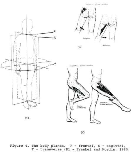
The knee joint is the largest and considered the most complex of the body's synovial joints. It is usually thought of as a modified hinge type joint but has slight pivotal as well as gliding movement. The knee is able to move in three planes of motion; frontal, sagittal, a nd transverse; with
flexion and extension in the sagittal plane accounting for the majority of motion. Figure 4 shows the three planes of
I
I I I I
--Dl
f ron t dl plan~ no r !on
D2 Add'ucuon
DJ
Figure 4 . The body planes. F - frontal, S - sagittal, T - transverse (Dl - Frankel and Nordin, 1980;
[image:20.573.61.506.146.660.2]The knee joint is held together by a complex pattern of ligaments and tendons. Damage or rupture of these connective tissues causes lack of contact in the joint and leads to
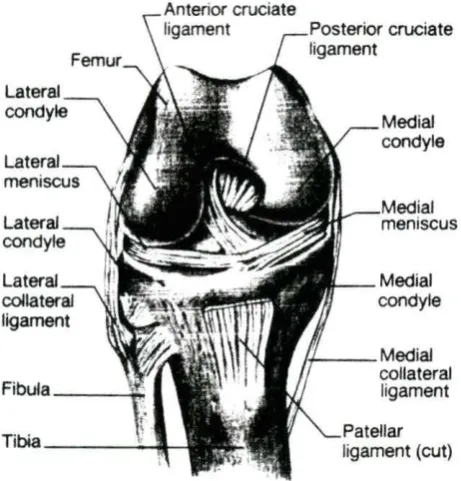
abnormal knee motion (Blacharski, et. al., 1975). The major ligaments include the posterior cruciate (PCL), anterior cruciate (ACL) , lateral collateral (LCL) , medial collateral
(MCL), and patellar; each of which can be further subdivided. The PCL functions to limit rotation and prevent forward
slippage of the femur. The ACL limits rotation and backwards slippage. Side to side movement is controlled by the lateral ligaments. Adduction (inward bending) of the tibia relative to the femur is limited by the LCL while abduction (outward bending) is limited by the MCL (Hole, 1984; Crowninshield, et al., 1976). For example, a lateral impact in football cause s adduction (medial movement) of the joint and a corresponding strain in the MCL. See figure 5 for anatomy of knee and ligaments.
Three separate articulating surfaces make up the knee joint; the femoropatellar and two tibiofemoral joints, eac h of which is covered by hyaline cartilage for protection. The
distal portion of the tibiof emoral surf aces are formed by
Lateral
Lateral collateral ligament
Fibula~
Tibia \l
Medial condyle
Medial meniscus
Medial condyle
,._ __ Medial collateral ligament
Patellar ligament (cut)
[image:22.572.181.412.297.538.2]Since the femoral condyles are rounded and the tibial
"condyle'' is basically a flat plateau, the joint is naturally unstable. Several internal and external structures help to correct this. Externally they include: a tough fibrous joint capsule (the body's strongest) which itself is strengthened by the iliotibial tract, tendons of the quadriceps, LCL and MCL, patellar tendon and ligament, and the popliteal ligaments. The ACL and PCL together form the internal support, crossing one another between the femoral condyles forming an "X" (hence the name Cruciate) and attaching to the central area of the head of the tibia and femur (Langley, et. al., 1974).
Knee Bracing
Although functional and rehabilitative knee bracing has been used for a long time, prophylactic knee bracing has been commonplace only since the 1970's, and there is yet much
(Baker, et al., 1987; Beck, et al., 1986; Brown, et al., 1986; France, et al., 1987; Knutzen, et al., 1987; Paulos, et al . , 1987; Tegner, et al., 1988). While each method has some benefits, no one test has yet provided the definitive answer .
Injury rate studies
The Anderson Knee Stabler one of the first brace
usage studies was done by Anderson, et al. (1979), on the Anderson Knee Stabler. They advocated use of their brace "as a preventative device by athletes in vulnerable positions." Anderson and his co-authors concluded this brace prevented significant valgus stress, reduced anterior-posterior laxity, and provided " excellent support to an injured knee." Also, the athletes did not complain of discomfort or show a decrease in performance while wearing the brace. Unfortunately, these conclusions are based on a total of nine football players; one player having played six games with the brace in use, and the other eight players all having used the brace for five or less games over a period of two years.
148 braced and 329 unbraced players. However, they still recommended the collection of more longitudinal data and
comparisons to other football programs to further evaluate the Anderson Knee Stabler.
These comparisons were made in studies done at Wake Forest University (Rovere, et al., 1987) and another at the University of Arizona (Hewson, et al., 1986), both on the Anderson Knee stabler. (The early studies on prophylactic knee bracing did not all use the Anderson brace. It was merely one of the first on the market having the benefit of good initial acceptance.) In their study at Wake Forest, Rovere, et al. (1987), looked at knee injuries occurring
one MCL injuries of the braced group and the forty seven injuries of the unbraced group despite impressions prior to the study that they had reduced numbers of injuries. One of their conclusions, therefore, was that the prophylactic knee brace used in the study did not improve knee injury
prevention.
General brace studies Six hundred and ninety-four
high school football players in two New Mexico school systems were studied by Grace, et al. (1988). Each player was matched with another of similar build and position on his own team. One player used a brace, a single upright design with either a simple hinge or a double hinge, and the other (control} was not braced. Grace, et al. (1988}, found athletes who wore the single hinged brace were significantly more likely to have knee injuries, more severe injuries, and more surgical
procedures than their control counterparts. The group wearing double hinged braces also experienced an increase in rate and severity of injuries but not to a statistically significant degree. They noted, however, an unusual number of other injuries to the lower extremity, particularly the ankle and lower leg.
edge of the brace support, were observed. The second year there were twenty eight lower extremity injuries not involving the knee. There was a "large and significant" difference in the rate of this type of injury between braced and non-braced players with braced players being three times more prone to injury. Grace, et al. (1988), hypothesized that since the biomechanical forces on the leg are altered by the brace, injury might be incurred elsewhere due to this transfer of force. They could not find any previous study that had documented this trend toward adjacent injuries. From their data, they concluded single hinge braces compounded the risk of injury and should not be used, and double hinge braces did not decrease the risk of injury.
A large pooling of records was attempted by Teitz, et al. (1987). They looked at seventy one NCAA Div-I schools in 1984 and sixty one in 1985. Teitz was able to gather the injury reports on 6307 players in 1984 and 5445 players in 1985 from these Div-I schools upon which to base their statistical
analysis. They were aware, however, of the possible
with comparing different schools and that the effects were likely to be small.
Teitz found that braced players in both 1984 and 1985 had a higher injury rate than non-braced players, and the results were statistically significant (1984: 11% vs. 6%; 1985: 9.4% vs. 6.4%). Interestingly, there was no significant difference
in 1984 when rates were compared for individual player position. In the 1985 study, there were significant
differences in some of the positions. They also found no association between playing surface and injury rates nor any difference in rates between types of braces. Overall, braced players had injury rates no better than non-braced players. Teitz and her colleagues concluded that "so-called preventive braces are not preventive and may in fact be harmful." This strong statement against prophylactic braces drew many
responses.
In letters to the editor of The Journal of Bone and Joint Surgery (1987), several authorities questioned the article by Teitz, et al., 1987. Robert F. McDavid, Ph.D., and Lonnie E.
Ph.D., stated that Teitz's own data shows injuries to be less severe when the braces are used based on the criteria of time lost from play. It appears the outpouring of response to this article was not only due to its content but also on the
emphasis placed on it by The Journal of Bone and Joint
Surgery. Paulos, in referring to the editorial preceding it (Cowell, 1987), questions the fact that Teitz's article
garnered lead position in The Journal of Bone and Joint Surgery and that the editorial seemed to condemn the use of
lateral knee braces.
Garrick, et al. (1987), reviewed six studies and outlined the criteria used by them in judging the effectiveness of
their braces. They identified factors which could have led t o incorrect conclusions in the individual studies, including incorrectly typing the injury, the number of injuries, the number of persons exposed to injury, and comparisons between different times and places. The studies Garrick reviewed also demonstrated knee injuries were associated with position
played more than any other variable. Allowing individuals to choose or dictate who wears the brace along with how injuries are defined both influence the data and subsequent
conclusions. For example, a player if given the choice, might elect to wear the brace only during practice for fear of
the players in positions regarded as ''unskilled" and not brace those in positions such as receiver or running back for fear of impairing their performance. Either choice would bias the results. Some authorities (Rovere, et al., 1987; Garrick, et al., 1987) agree games are more dangerous than practices and certain positions (eg., linemen, running back, linebackers, tight ends) are more susceptible to injury than other
positions. Defining and grading injuries can also change over time, as new medical methods are developed and as team
physicians change, influencing, for example, how an injury as minor as a sprain is diagnosed.
Garrick, et al. {1987), commented the practical solution to bracing might be to use braces for whatever benefits they might provide. Some studies (Teitz, et al., 1987; Grace, et al., 1988), though, have shown that there are some possible negative side effects to using prophylactic braces. For this
reason, they neither supported nor totally rejected using braces in contact sports.
The Ampro Knee Brace Another prophylactic brace,
having two uprights (see figure 6), as opposed to one on the Anderson brace, has been used and evaluated at Iowa State
more than a three percent loss over a timed agility course. The players indicated confidence in the brace and its comfort. Only one injury was reported during twenty days of spring practice, while nine injuries were reported the previous year of practice without the brace. No statistical conclusions were drawn from these numbers, only that more study was needed upon which to base valid conclusions.
A follow-up study was done by Brodersen and Syrnanowski (1988). They looked at time loss and injury severity recorded in ISU football medical files from 1979 to 1987 to judge the effectiveness of the Arnpro brace. Their findings indicated an eighteen percent reduction in knee injuries along with some reduction in player time lost. From this, they concluded use
of the Arnpro brace offered 11 ••• a significant reduction in both
the overall knee injury rate and the proportion of serious knee injuries."
Uncontrollable variables The various researchers in
all of the previously mentioned studies noted other factors which complicated their analysis of knee injury rates.
(Garrick, et al., 1987; Hewson, et al., 1986). The NCAA has continually changed and modified rules in an attempt to reduce injuries. All of these things constitute uncontrollable
variables that confound the statistical results. Some have suggested that these variables are negated by large
statistical populations and by long term, inter-program
studies (Teitz, et al., 1987), but this remains to be proven. In addition, it is possible a favorable bias of results could occur due to the instituting of bracing after a disastrous season and, therefore, the tendency of the number of injuries to naturally revert to a more normal, lower value even without bracing. That is, the effect of regression of the sample
population mean back to the level of the whole, or true,
population mean regardless of the influence of factors such as knee bracing (Teitz, et al., 1987). Brodersen and Symanowski
(1988), believed they had overcome and negated this phenomenon by the length of their study (eight years). Hewson, et al.,
(1986) however, concluded that knee injuries on a team are "a random event with rare occurrence" in light of the number of chances for an injury to occur. Rovere, et al. (1987) stated the naturally occurring frequency of injuries may not be
The problem of adequate sample size is another
complicating factor. Due to the relative infrequency of MCL injuries, for example, statistical differences are often
difficult to resolve. Garrick, et al. (1987), identified this statistical problem with sampling size.
If we assume the overall rate of MCL injury to be that found in the WF study, for a 90% chance of finding a 50% reduction in MCL injuries (from 13.5 to 6.75 per 100 player-seasons) with a one-tailed test at the 5% level of significance, it would take 250 to 300 athletes in each group, or a total of 500 to 600 player-seasons of exposure. To detect smaller, perhaps more realistic reductions, much larger numbers would be required.
Reliably detecting an increase in ACL injuries would be even more difficult, as they occur about one-fourth as often as MCL injuries. Player-seasons exposures in excess of 4,000 would be required to have a 90% chance of detecting a 50% increase at the 5% level of
significance. For this reason alone, carefully
designed, multicenter studies will be essential if these controversies are to be satisfactorily resolved.
Obviously, unless a new brace is dramatically better than the control, or injury rates increase drastically, these
controversies will continue for some time to come.
Biomechanical testing
Prophylactic braces A biomechanical force test was done by Brown, et al. (1986), on the Ampro Knee Brace and a unilateral brace. Their test was designed to simulate a
knee joint was then struck by a concave impactor driven with a servohydraulic motor. A liquid metal strain gauge was sutured to the MCL which, when stretched, would produce linear voltage changes in the liquid metal (mercury) . The strain
measurements were then paired with the corresponding
measurements of valgus load applied, knee deflection, and the testing machine command stroke signal (when the loading
started and stopped). The test took approximately 370 milliseconds during which time the valgus load reached 625 Newtons and an MCL strain of about 7.1%.
The tests showed an average relative strain relief (unbraced strain minus braced strain divided by unbraced strain) of 18.3% for the unilateral brace and 25.1% for the bilateral brace. These were statistically significant from the unbraced leg but not statistically different from each other. There was no statistical difference between the apparent stiffness of the braces, defined as the change in
force divided by the distance the knee was deflected. Brown concluded there was "reasonable evidence'' the braces helped protect the knee to some extent.
and to define the mechanical properties of several commercial braces. They believed the mechanical and material properties of the brace under static and dynamic loads were important to understanding its function in vivo. Using an Instron machine, specimens were subjected to static nondestructive and low rate destructive loads in a three point bending fixture. Low rate loads were calculated as 73% strain/sec., equivalent to a lateral impact of about two tenths of a mile per hour, and a somewhat higher rate (to test the load rate dependency of the MCL) of 856% strain/ sec., or 2.35 mph.
Results showed substantial data variation between individuals but much less on repeated tests of a single
sample. Static testing of the Anderson Knee Stabler and the McDavid Knee Guard showed little change i n the engineering bending stiffness on the knee. However, Paulos, et al.
(1987), concluded that static testing was sufficient to judge a braces on field performance, because impacts were longer in duration than the natural frequency of either the braces (most were greater than 100 Hz) or the knee (10 Hz).
Low rate failure testing by Paulos, et al. (1987),
yielded peak ligament tensions of 1122 N for the ACL, 1406 N for the PCL, and 2346 N for the MCL at the point of rupture. Their contributions to valgus restraint were 11% (ACL) , 9%
ultimate rupture loads and higher stiffnesses in the MCL but decreased strain accommodation, ie., the ligaments ability to withstand strain.
Citing brace rigidity (those tested were less rigid than the knee), and joint line clearance, or its lack (ie. the space between the hinge and the knee), Paulos felt these
braces were not effective in preventing harmful valgus forces. More study was needed on the combined biomechanical
relationship between the knee and the brace with regard to its mechanical and material properties.
A follow-up study was done to access the impact response of the braced knee (France, et al., 1987). They tested
several commercially available braces, including the two prophylactic braces used in the Paulos (1987) study, with impact loading. The impact tests were done on a complex mechanical knee joint/ leg/ lower torso apparatus designed to mimic the function of the human knee as closely as possible. The resulting "surrogate" knee was so unique, it was patented.
standing surrogate under varying impactor masses, flexion angles, and with the hip and foot either constrained or
unconstrained, using both braces and no brace for comparison. Results showed the MCL tension was greater for fixed foot vs. free and straight leg vs. flexed when using a constant
impact force. The braces (Anderson and McDavid) were most effective, in general, with higher mass/ low velocity impacts
(vs. low mass/ high veloci ty impacts of the same energy), fixed foot and hip, and straight leg alignment. The braces were rated by an Impact Safety Factor (ISF), defined by France as
MCL peak tension, unbraced/impact momentum, unbraced MCL peak tension, braced/ impact momentum, braced
The Omni Anderson rated 1.29 ISF and the McDavid rated 1.18 ISF. France proposed a minimum ISF of 1.50 as a standard level of safety which equates to a 30% reduction in MCL load. Several functional braces that were tested did rate higher than the two prophylactic braces. Interestingly, the only brace that just met the minimum ISF was made by a company tha t supported this research project. France, et al. (1987),
concluded that the current prophylactic braces available were biomechanically inadequate. They believed, however, based on further refinements of brace material properties and
In a different study, which also used the Anderson Knee stabler, the McDavid Knee Guard, and several functional braces on cadaver legs, Baker, et al. (1987), had similar results . They measured force in the MCL and ACL, and abduction angles with an electrogoniometer due to valgus loads at three angles of knee flexion. The two prophylactic braces demonstrated
from O to 6% reduction in abduction angles at the various angles of flexion while the functional braces were somewhat better at O to 23%. The prophylactic braces did not reduce the measured force in the MCL and one, the Anderson Knee Stabler, seemed to increase the force on the ACL.
Baker concluded from his data that functional braces, especially those with more soft tissue containment, provided some protection for the MCL while prophylactic braces gave little or no protection.
Functional braces Several other studies dealing only
with functional braces are noteworthy in the examination of prophylactic bracing if only because of the similarity in design features of the two types of braces.
Knutzen, et al. (1987), examined the Marquette Knee Stabilizer and the Generation II knee braces. An
They reported a reduction in varus/valgus motion of
approximately four degrees (24%) for both braces.
Beck, et al. (1986), tested seven functional braces.
They used a Stryker Knee Laxity Tester and a Medtronic KT-1000
device to measure anterior tibial displacement on three
patients. Although some braces were reported as better than
others, no statistical differences were evident due to the
small sample size combined with the small amount of protection
afforded by each brace.
Two studies evaluated the Lenox Hill brace (Colville, et
al., 1986; Wojtys, et al., 1987). Colville looked at forty
five patients with ACL deficiencies and compared the brace to
no brace in anterior subluxation of the tibia, rotary
instability, and lateral instability. They also used a
subjective questionnaire to determine satisfaction with the
brace. Their results showed some improvement in objective
stability measurements but the perceived functional
the bones. The data showed the Lenox Hill brace decreased anterior translation from 10.2 mm to 5.6 mm at thirty degrees of flexion under no axial load. The brace also decreased external rotation of the tibia an average of seven degrees after the ACL was sectioned. Under all other sets of
conditions the Lenox Hill brace did not improv e the protection of the knee.
Four derotation braces and an elastic knee cuff were
evaluated by Tegner, et al. (1988), using an electrogoniometer to measure range of motion in all three planes. The braces' effect on strength was tested on a Cybex II isokinetic device and their effect on performance was tested by running a figure eight. In a slideboard test, simulating skating, all braces reduced abduction/ adduction by about forty percent. The elastic cuff showed no effect. The strength and performance tests showed some reduction when wearing the braces. Tegner concluded that although the braces showed some benefits, nothing was proven concerning how much force they could resist, which would be an important factor.
Modeling Knee Joints
Mechanical models
A benefit of mechanical models over cadaver testing, however, is working with fewer constraints. The model is readily
available, can be built to exhibit as few or as many variables as needed, and does not come with regulations concerning its
use as do cadavers. Quoting Nisell (1985), 11 • • • the knee
biomechanical model is considered as a useful instrument for quantifying knee joint forces." Researchers are now faced with the task of determining how best to make the model and what materials to use.
A mechanical model has several basic components related to the basic anatomy of the leg. The bone structure provides the rigid shape of the model and may be cast from a material to exactly match the surface features of a real bone or it may be of a more general shape, ie. a metal rod or tube. Aluminum has been shown to have good characteristics relative to
strength and bending that simulate the bones (Mason, et al., 1989). The material choice, however, is not critical so long as it has the general physical characteristics of bone.
Mason, et al. (1989), said that fixing the foot and hip
effectively makes 11 •• the leg into a rigid beam with the knee
as the weak spot.". This scenario woul d obviously be the worst case, more likely to cause injury than if the body could deflect with the motion of the impact. The surrogate knee of Mason, et al. (1989), was a l so capable of a free standing position, which allowed i mpact tests on a deflectable target.
The knee joint itself has been r epresented as a simple hinge or shaped to form the c ondyles of the femur and tibia. The hinge limits the degrees of freedom of motion and so restricts the i nformation that can be obtained from it. The more natural condyla r surface, if properly formed with
anatomically correct ligament placement, can produce the most lifelike results. However, the natural shape is difficult to duplicate and also is very hard to hold together in its
natural position (Mason, et al., 1989). The more lifelike results are necessarily more complex, though, and therefore more difficult to interpret. Other designs fall between these extremes including ball and socket types, saddle joints, or gliding joints (Hole, 1984).
The ligaments themselves are variously made of springs, cables, elastic bands or combinations of these or other connective materials. A simple model used by Smi th, et al.
No data on the physical characteristics of these springs was provided. A much more complex model combining sheathed steel cables connected to springs of known load constants was used by Mason, et al. (1989). The individual spring associated with each cable, which in turn represented an individual ligament or tendon, was chosen to have the correct strain characteristics of the element it represented. The
force/elongation properties of the cables were likewise known and combined with that of the springs. As was stated before, however, the exact material characteristics are not critical and do not have to perfectly match their anatomical
counterparts; they merely have to have known values and be reproducible in repeated test procedures (Mason, et al., 1989) .
When constructing a mechanical model with the intent and purpose being to apply braces to it, the tissue over the bone must also be considered. The force on the brace is meant to be transferred to the leg and away from the knee joint.
Pressure on the skin surface from the brace is transmitted in a diffuse way through the tissues to the internal bone
load dissipation between the force on the brace and that
measured on the ligaments. Obviously, a direct connection of the brace to the bone by rigid means would have a stiffening effect, but would not be a realistic representation of brace
usage.
Mathematical models
Mathematical models simulate and take into account the geometry of the knee, the ranges of motion, and the different physical characteristics of the parts of the knee joint. In order to do this, they must rely on previously obtained
physical data on which to base the mathematical relationships . The bone and condylar surf aces are generally represented as rigid bodies with the soft tissue, ligaments, and tendons treated as linear or non-linear springs or beam type elements
(Crowninshield, et al., 1976; Wismans, et al., 1980; Andriacchi, et al., 1982).
The ligaments, although strong in resisting tensile loads, do exhibit mild visco-elastic properties as they will stretch to a limited degree under force. A simple approach to model this behavior was used by Wismans, et al. (1980), and by Andriacchi, et al. (1982). They used various arrangements of strong springs to allow limited elastic movement of the
quadratic force elongation relationship to explain the mechanical behavior of the ligament
1
= k
*
{l - lo>
2~ was in Newtons,
k
being the spring constant,l
the stretchedlength of the spring, and
lo
the initial length of the spring.The constant used for the MCL was divided into the anterior and posterior parts, e a ch being fifteen Newtons per square millimeter. Andriacchi, et al. {1982), used a the folowing
force elongation relation without squaring the difference:
f =
k
*
6X{6X was the displacement,
{l-lo),
of the spring element)MATERIALS AND METHOD
The objective was to test the effect material stiffness had on the brace's ability to protect the knee. An apparatus was constructed upon which to conduct impacts on the knee either with or without the brace. A single brace design was used and uprights made of three different materials were tested. The data from these impacts was collected by a program onto a personal computer for later analysis.
The Test Apparatus
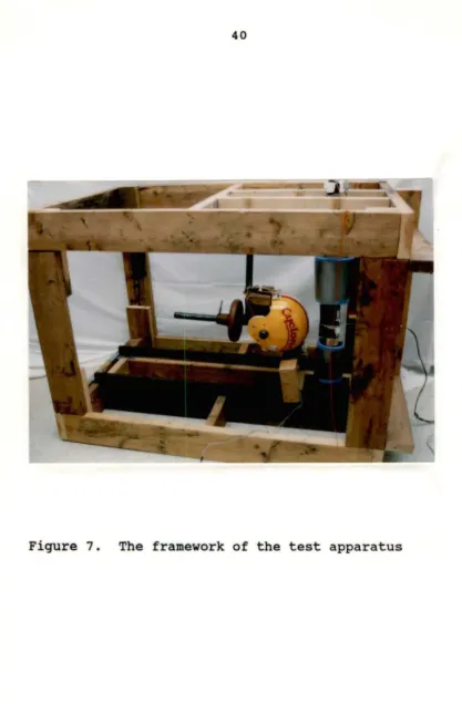
The apparatus used consisted of a wooden framework used to support a pendulum, an artificial leg, and sensors with which to collect the data (see Figure 7) .
The framework
The supporting frame for the artificial leg and the impactor pendulum was constructed of two by six inch lumber . The members were glued with construction grade adhesive and nailed with eight penny nails for maximum strength. The height of the frame was dictated by the length of the
"average" leg. This will be discussed further in the section entitled "The Artificial Leg."
frame within the main frame. This hinged frame allowed the ankle pin to move upward slightly as the knee joint was bent during impact. As the knee joint was bent, its vertical height decreased slightly. The hinged frame, however,
prevented the artificial leg from moving laterally with the impact and together with the upper fixed hip pin prevented rotation of the leg. The pins at the ankle and hip allowed only lateral motion of the leg (in the frontal plane) of the test apparatus, and were inserted into bearing sleeves that had been firmly pressed into the aluminum leg. The steel pins were isolated from vibrations in the framework by rubber plugs around their ends where they fit into the wooden frame (see Figure 8).
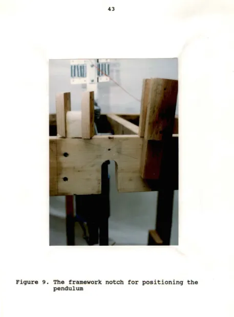
The framework above the pendulum was notched to accommodate the arm of the pendulum. The notch could be fitted with different plugs to position the pendulum so it would be swung from the same height each trial. The pendulum could be released from thirty, sixty or ninety degrees of arc. The pendulum was manually pulled back until it was in firm contact with this notched position and then released (see Figure 9).
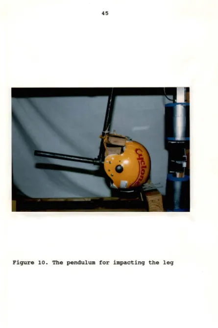
The pendulum
A pendulum was used to impact the knee joint of the
an axle inserted into bearing sleeves at the same height as the hip pin. It was located at a horizontal distance from the hip pin so that it impacted the knee joint at the bottom most point of its swing, at which point it had its maximum
velocity. The pendulum was made of three quarter inch "black " pipe with a "T" at the bottom angled away from the point of
impact. Additional weights could be placed on this "T" section to change the mass of the pendulum. The impactor surface was an actual football helmet attached to the
pendulum. This gave the pendulum a realistic, large, rounded contact point with which to hit the knee joint (see Figure
10) •
The artificial l.gg
The leg was made from square aluminum tubing with one eighth inch wall thickness. Aluminum has been found to have the desirable characteristics of strength, stiffness, and
bending that are similar to bone (France, et al., 1987; Mason, et al., 1989). Square tubing was chosen to limit torsional moti on on impact. The sides of the square help direct the bending force into the frontal plane even if the impact was slightly off center.
femur is 45.7 cm giving a total leg length from ankle to hip of 80.8 cm . The thigh and calf circumferences were also constructed to match the "average" 1985 male to provide the proper soft tissue bulk under the cuffs of the brace. They were 59.5 cm and 37.5 cm, respectively.
The tissue bulk was built up on the square tube in three layers. First, half moon shaped strips of wood were applied to give the square tube a round shape. Second, commercially available "Bio-Soft Gel" terry cloth covered wrist weights were slipped onto the tubes from each end. These gave the leg added inertial weight and also the firm sponginess of real muscle tissue. Finally, the Gel layer was wrapped with closed cell Ensolite foam to g i ve the leg the required circumference
(see Figure 11).
The knee joint itself was modeled as a s i mple hinge. A heavy duty strap type hinge was bolted to the distal end o f the femur and the proximal end of the tibia. The axis (or pin) of the hinge was on the lateral side of the test leg. Normal sagittal bending of the knee would dictate putting t he axis of the hinge on the posterior side of the test leg.
Since no motion in any plane but the frontal plane was to be measured, the bending action of the hinge was in this plane
leg held by the hinge (the lateral side of the model knee) causing it to bend open on the medial s i de. This bending action was resisted by the artificial medial collateral
ligament (a steel cable) (see Figure 12).
The MCL was modeled by a three-eighth inch diameter, seven by nineteen stranded steel cable with a work ing l o ad
rating of nine hundred eighty pounds (Mason, et al., 1989 ) .
The distal end was anchored to the lower tibia by two cable clamps. The cable passed over the medial joint opening along the center of the aluminum tube, gliding on two grooved Teflo n blocks, one on either side of the joint, minimizing fricti on on the cable during bending of the leg. The cable wa s
retained and guided along its path by s everal eyelets. Th e proximal end of the cable was clamped onto a bar attached t o a set of six springs. The springs transmitted pressure via a steel "U" bolt and flat plate to a quartz load cell (see
Figures 12,13,148&14b).
The spring set had a constant of a pproximate l y 4 70
Newtons per centimeter (see Figure 15) whi ch is somewhat l e s s
than that used by Andriacchi, et al. (1982). The springs
allowed stretchability similar to a ligament when tension was put on the cable. The springs themselves were all
Figure 13. Close-up view of the quartz load cell,
[image:58.564.48.528.47.721.2]Figure 148 and 14b. These photos show two views of the set of
[image:59.563.35.532.18.726.2],....
f/I
c
0
"i
Cl)z
c ...,
900
800
700
600
500
400
300 ... .
200 ... ... .
100 ···
04-~~4-~~-+-~~-+-~~-+-~~--+~~-+~~---t~~--1~~--1
0.0 0.2 0 .4 0.6 0.8 1.0 1.2 1.4 1.6 1.8
Dlsplacement (In centimeters)
[image:60.572.79.487.152.642.2]The brace
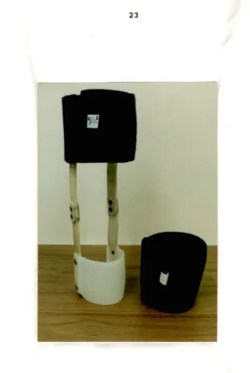
The brace style used in this research was the Ampro Knee Guard, a bi-lateral prophylactic brace. The uprights were
fabricated of nylon and the cuffs from a combination of polypropylene and polyethylene. The exact chemical composition of both the uprights and the cuffs was not
reported in Randall, et al., 1984. The cuffs were held onto the leg by bands of neoprene with velcro attachments (see Figure 6).
The Ampro Knee Guard was modified for use in the two
other experimental conditions. The original nylon uprights of the brace were removed and duplicated in 6061-T6 aluminum as well as graphite fiber. Figure 16 shows the relative bending
stiffness of the aluminum upright and the plastic upright. The aluminum and graphite configurations were much stiffer than the plastic, and should, therefore, according to the hypotheses of this research , result in less knee displacement than either the control or plastic configurations.
The sensors
140
IT
.
I
;
120
I
t
~race-
F
-100 ... ··-···
·1
upright1
.'
~l/Oc
.. ---11
80mm L mmmmmmmmmm
m ·
·1---
'~·-
-
-r
Q)
z
[image:62.567.75.493.139.623.2]c
...
8
60...
0
,,._
40 ···
20 ..
o.J-=====--+----+---+----+---+---+---~
0.0 0.5 1.0 1.5 2.0 2.5 3.0 3.5
Displacement (In centimeters)
+
Plastic ~ Aluminum -+- GraphiteThe load cell was connected to a Kistler Model 568 Universal Electrostatic Charge Amplifier. The amplifier
converted the static electrical discharge of the quartz load cell into DC volts per unit of force on the cell. This output was fed into a Keithley analogue to digital converter and then to a personal computer.
A manual calibration of the paired load cell and charge amplifier was done prior to testing to double check the
accuracy of the calibration data supplied with said
instruments. Once calibrated, the settings on the paired instruments were untouched throughout testing and only the baseline was zeroed (grounded) prior to collecting each set of data. The procedure followed for calibration and zeroing was performed as per the instruction manuals supplied by the
manufacturer. The analogue output of the charge amplifier was ten millivolts per pound of force (or per 4.45 Newtons). At this setting it was capable of sensing forces up to 1,000 pounds, the approximate limit of the working load of the cable, and more importantly a force high enough to rupture a real ligament. Actual applied loads during testing only reached about half this limit.
Transducer. The transducer was used to measure sideways displacement of the knee during the less forceful, lower weight impacts. The higher weight impacts pushed the knee beyond the range of this device.
The voltage output of the transducer was connected
directly to the Keithley A/D converter. Output was manually calibrated prior to testing. The transducer was clamped to the frame of the testing apparatus while the moving core rod was attached to the knee joint. This method of connection allowed the rod to freely piston in and out of the transducer
(see Figure 17).
Data Acquisition Program
Data were collected (on an IBM personal computer) under the control of a program written in QuickBasic. The program
(Appendix A) read the digital signal from the Keithley A/ D converter and stored the information on disk. The stored data were analyzed using a Microsoft Works spreadsheet. Averages,
standard deviations, and statistical differences were
calculated while in this spreadsheet. All graphs and charts using the data were also created by this media.
The final form of the Basic program took approximately
Figure 17. The displacement transducer is attached to the
frame by a pivoting clamp. The core rod is
[image:65.566.68.507.57.709.2]During this loop, it read data from the quartz load cell and the displacement transducer.
The duration of the impact event was about 100 to 170 milliseconds depending on the test conditions, therefore, the
impact frequency was 6-10 Hz. In order to get a valid sample, at least two or more samples per cycle must be taken (Black, 1953). That means twenty or more samples per second were needed. Since the sample rate of the program was much higher , many other frequencies were being detected. These unwanted
trial t o trial was coordinated for valid comparison.
Variations of no more than two or three milliseconds between trials were apparent.
Data Analysis
First, the data were imported into a Microsoft Works
spreadsheet for calculations and comparisons. There were four cases of cable (ligament) tension data for each of the two pendulum weights and four cases of displacement data for the lighter pendulum weight. The four cases represented the control data (impacts on the leg with no brace), the plastic Ampro brace (as manufactured), the Ampro modified with
aluminum uprights, and the Ampro modified with graphite
uprights. There were twelve spreadsheets in all, one for each case. Each case resulted in a spreadsheet of fifty trials
RESULTS
The data collected in this research supported the original hypothesis. That is, the material chosen in the manufacture of bi-lateral prophylactic brace uprights
influenced the level of protection afforded by the brace to the knee. The following results indicated a stiffer material provided a greater degree of protection than did the original brace configuration or no brace at all. However, there was an
increase in force transferred brought about by the increase in stiffness of the brace. When hit with impacts of equal
momentum, the stiffer brace returned to normal more quickly than the relatively more flexible brace (or no brace). This shorter duration of impact for the stiffer brace caused the force transferred to the leg to be greater even though the momentum was the same.
Low Impact Force
The pendulum in the low impact case was released from sixty degrees of arc with a total mass of 6.68 kg. The velocity at the bottom of the arc (the point of impact) was 2.25 m/s or 5 . 03 mph. Velocity was calculated from:
Momentum of the pendulum was defined to be the mass of the
pendulum times its velocity (M = m*v), which in this situation
is 15.03 kg*m/s. The momentum was held constant from trial to trial and case to case.
From Newton's Second Law, the summation of force imparted to the knee by the pendulum is the change in momentum divided by the length of time necessary to transfer the force . This force is not always the same from case to case as the time of contact between the pendulum and the knee varied with the type of brace. In all trials, however, the cases using the
graphite and aluminum braces had shorter durations of impact (by about twenty eight milliseconds) than did the control case. The plastic braced knee had shorter impacts than the control case by about ten milliseconds. This means the total force experienced by the braced knees was up to twice as much as that experienced by the control knee, due strictly to the duration of impact.
As can be seen on Figure 21, the durations of impact for the control, plastic, aluminum, and graphite cases are 55, 46, 27, and 27 milliseconds, respectively. The resultant
Displacement
Due to the mechanical setup and the limited range of the displacement transducer, high impact forces caused the lateral displacement of the test knee to be greater than the
transducer was capable of measuring. For this reason, measurement of displacement was only carried out under the condition of low impact force.
Control The test knee with no brace applied was
displaced laterally a maximum of 4.80 cm (1.89 in.) on
average. The standard deviation of this maximum was .03 0 cm (.012 in.), which is only 0.6% of the mean. See Table 1 and Figure 19.
Plastic brace In this case, the test knee wore the
Ampro Knee Guard as manufactured and with no modifications. The maximum displacement, as can be seen in Table 1 and Figure 19, was reduced to 4.62 cm (1.82 in.) from that of the control case. The standard deviation of the maximum is .048 cm (.0 19 in.), a 1.0% variation. This maximum displacement represents a 3.6% reduction from that of the control case . The reduction
is significant at p < 0.01.
Control
STATISTICAL COMPARISON OF DISPLACEMENT MEASUREMENTS
The maximum displacement (the peak of the curves in Figure 19) is the average of 50 trials for each case.
All percent reductions from control are significant at P < 0.01
Maximum
Displacement Deviation Standard
I I
4.80 cm • 0.030 cm •
...
,
% of Control 100 % Reduction from Control 0
Statistical Results: d.f.
=
98 t value compared betweenControl Plastic Aluminum
1.89 in : 0.012 in : :
11---11---+---+---+---4.62 cm : 0.048 cm :
••••••••• •••••••••••••••••••••••••••oo~ooo• •OOOO•••"' ••OO O•OO OO OO••• ! 96.4 3.6
1.82 in I 0.019 in I I
lt---i~---+---+---+---Plastic
Aluminum
...
3.86 ~:;;··:··· cm....
t····~:~·~-~--~···1 : 0.036 cm : 80.6 : 19.4lt---4~---+---+---
---+---Graphite ... 3.81 cm ~ : ... . 0.025 cm :
79.6 20.4
1.50 in 0.010 in
140.4 I 89.3
I
--- +---- ---~~~==~!
[image:72.784.129.637.141.404.2]1.800 4.572
1.600 4.064
1.400 3.556 ...
... c E
~ ~ (J
-
c-1.200 3.048 c
ID ID
E E
ID ID
> >
0 0
:I 1.000 2.540 :I
ID ID
ID ID
c c
~ ~
°'
0.800 2.032 Ul
0 0
""
ID
""
-
ID0
-...J 0.600 1.524 ...J 0
0.400 1.016
0.200 0.508
0.000 0.000
0 18 36 54 72 90 108 126 144 162 180 198 216 234
Time (ms)
--
Control -+- PlasticAluminum - Graphite
[image:73.778.118.661.65.480.2]axis), the raw displacement values were added together for each mean curve. The "Maximum Area" shown in Table 2 is not really a two dimensional area, but rather a summation of the individual data point values for each mean curve.
The area values in Table 2 should be thought of as the relative amount of displacement along with the amount of time that the knee was displaced. A large "Maximum Area" number would indicate either a greater displacement, a greater length of time displaced, or both (e.g. the control case as shown in both Table 1 and Figure 19). The 138.88 in. for the plastic case (Ampro Brace), is a 6.4% reduction from the 148.38 in. of the control case.
In most cases, the percent reduction from the control case is greater when looking at Table 2 than when looking at Table 1. As can be seen from Figure 19, the reduction in area
is due not only to the lower maximum displacement but also the fact that the curve returns to zero sooner. The added
stiffness of the brace on the test leg most likely caused this quicker "spring" back to zero displacement. Figure 20 shows graphically the percent reductions listed in Table 2.
Note should also be taken of the positive slope portion of all three braced case curves on Figure 19. Although there is area under these curves that is not under the control
Control
The maximum area value is a summation of magnitudes (in inches of displace ment) of the individual
sample points which make up lhe mean curves of Figure 19. The column "% of Control" is shown
graphicgaUy in Figure 20. All values are significant at P < 0.01
Maximum Area (inches)
Standard
Deviation Control % of
I I I
%
Reduction from Control
148.38 I 0.694 I 100 I 0
Statistical Results: d.f. = 98
t vaJue compared between
Control Plastic Aluminum
lt---·~---+---+---+---Plastic 138.88 : 1.683 : 93.6 : 6.4
t---1~---+---+---+---96.64 : 1.011 : 65.1 : 34.9
·~---1~---~---+---+---Aluminum ---~---298.3 : 152.1
[image:75.785.164.616.221.376.2]e
-
c 0u
-
090.07. ... .
80.07. ... .
70.07. ... .
60.07. ···
50.07. ... .
40.07. ... .
30.07. ... .
20.07. ... .
10.07. ... .
0.07. +
-Eiil Control Cim Plastic • Aluminum IWJJ Graphite
[image:76.783.146.690.48.475.2]zero baseline. The apparent reason that all three braced case curves have the positive slope portion of their curve sooner than the control case is the added width of the brace. The pendulum came into contact with the braced test leg several milliseconds sooner (after triggering the photo cell) than it came into contact with the unbraced test leg. The hinge of each brace was a half inch thick or 1.27 cm. There was also several millimeters space between the hinge and the joint
surface. At the pendulum's maximum velocity of 2.25 m/s, this extra 1.3 to 1.4 cm would equate to the pendulum hitting about 6 ms sooner.
Aluminum brace Maximum displacement with the aluminum
brace was 3.86 cm (1.52 in.), a reduction of 19.4% from the control and 16.5% from the plastic brace. The standard deviation of .036 cm was only 0.9% of the maximum. The
difference between the aluminum case and both the control and
plastic cases was significant at p < 0.01.
The area under the aluminum brace curve was 96.64 in., a reduction of 34.9% from the control case and 30.4% from the plastic brace. Both reductions were significant at p < 0.01. The standard deviation of the aluminum curve area was 1.01 (or 1.0% of the value).
Graphite brace The original Ampro brace was again