DRAFT
Final Report
AFRL SBIR Phase 3 Project
Indiana University
Sensor Cloud Project
TABLE OF CONTENTS
1. SENSORCLOUD ARCHITECTURE
1.1 SensorCloud Overview
1.2 Sensor Cloud Middleware
1.3 Grid Builder
1.4 Sensor Grid
1.5 Sensor Service Abstration Layer
1.6 Container Service
2. USER GUIDES
2.1 SensorCloud components
2.2 Deployment and User Guides
2.2.1 Tutorial of sensor deployment 2.2.2 User Guides for Sensor
2.3 How to develop sensors and clients
2.4 Advanced Guide to develop sensors and clients
2.5 Sensor Cloud development: An overview
2.6 NaradaBroker Distribution
2.7 LDAP Security feature
2.8 Rest Easy
2.8.1 Guide for SensorCloud Client End users 2.8.2 Guide for SensorCloud client developers
2.9 Streaming Web Server
2.10 Configuring dynamic deployment of domains 2.11 OpenStack Compute: Deployment and Overview
3. PERFORMANCE METRICS
3.1 This section will be completed by May 7th!
4. APPENDIX
4.1 APPENDIX A Secure Cloud Computing with Brokered Trusted Sensor Networks
1.
SENSORCLOUD ARCHITECTURE
1.1
Sensor Cloud Overview
Introduction
Anabas, Inc. and the Indiana University Pervasive Technology Institute have partnered to develop a Sensor-Centric Middleware System hereafter referred to as the Sensor Cloud.
The objective of the Sensor Cloud Project is to provide a general-purpose messaging system for sensor data called the Sensor Grid Server, and a robust Application API for developing new sensors and client applications. The key design objective of the Sensor Grid API is to create a simple integration interface for any third party application client or sensor to the Sensor Grid Server. This objective is accomplished by implementing the publish/subscribe design pattern which allows for loosely-coupled, reliable, scalable communication between distributed applications or systems.
Publish/Subscribe Architecture
The publish/subscribe (pub/sub) design pattern describes a loosely-coupled architecture based message-oriented communication between distributed applications. In such an arrangement
applications may fire-and-forget messages to a broker that manages the details of message delivery. This is an especially powerful benefit in heterogeneous environments, allowing clients to be written using different languages and even possibly different wire protocols. The pub/sub provider acts as the middle-man, allowing heterogeneous integration and interaction in an asynchronous (non-blocking) manner.
The pub/sub architecture uses destinations known as topics. Publishers address messages to a topic and subscribers register to receive messages from the topic. Publishers and subscribers are
generally anonymous and may dynamically publish or subscribe to the content hierarchy. The system takes care of distributing the messages arriving from a topic's multiple publishers to its multiple subscribers. Topics retain messages only as long as it takes to distribute them to current subscribers. Figure 1 illustrates pub/sub messaging.
Message publication is inherently asynchronous in that no fundamental timing dependency exists between the production and the consumption of a message. Messages can be consumed in either of two ways:
• Synchronously. A subscriber or a receiver explicitly fetches the message from the destination by calling the receive method. The receive method can block until a message arrives or can time out if a message does not arrive within a specified time limit.
Figure 1 Elements of a Publisher/Subscribe System
A publish/subscribe system can be conveniently implemented using a Java Messaging Service (JMS) compliant Message-Oriented Middleware (MOM) such as NaradaBrokering, ActiveMQ, SonicMQ etc. to handle message mediation and delivery.
Sensor Cloud Overview
The Sensor Cloud implements the publish/subscribe design pattern to orchestrate communication between sensors and client applications which form an inherently distributed system.
• Sensor Cloud Server creates Publisher-Subscribe Channels (Represented as a JMS Topic)
• Sensors acting as publishers create TopicPublishers to send messages to a Topic
• Client applications acting as subscribers create TopicSubscribers to receive messages on a topic
• Apache ActiveMQ is used as the default underlying MOM and any other JMS style broker can be used as well.
Figure 2 shows a high-level overview of a typical deployment scenario for the Sensor Grid. Sensors are deployed by the Grid Builder into logical domains; the data streams from these sensors are
Figure 2 Schematic of the Sensor Cloud
Examples of physical devices already implemented include:
• Web/IP Cameras
• Wii Remotes
• Lego MindStorm NXT Robots
• Bluetooth GPS Devices
• RFID Readers
However Sensors can be made from chat clients, Power Point presentations, web pages virtually anything which produces data in a time-dependent stream can be implemented as a Sensor Grid sensor.
High-Level Sensor Cloud Architecture
The main objective of the Sensor Cloud Project is to design and develop an enabling framework to support easy development, deployment, management, real-time visualization and presentation of collaborative sensor-centric applications. The Sensor Grid framework is based on an event-driven model that utilizes a pub/sub communication paradigm over a distributed message-based transport network.
The Sensor Grid is carefully designed to provide a seamless, user-friendly, scalable and fault-tolerant environment for the development of different applications which utilize information
(SSAL). Narada Broker (NB) is the transport-level messaging layer for the Sensor Grid. The overall architecture of the Sensor Grid is shown in Figure 3.
Figure 3 Sensor Grid Components
Sensor Grid Server (SG)
The SG mediates collaboration between sensors, applications and the GB. Primary function of SG is to manage and broker sensor message flows.
• Sensor/SG flow - The SG keeps track of the status of all sensors when they are deployed or disconnected so that all applications using the sensors will be notified of changes. Sensor data normally does not pass through SG.
• Application/SG flow - Applications communicate application API, which in turn
• Sensors’ properties are defined by the sensors itself. Applications have to obtain this information through SG.
• Application/Sensor flow – The SG provides each application with information of sensors they need according to the filtering criteria. The application then communicates with sensors through the application API for receiving data and sending control messages.
Application API
The Sensor Grid aims at supporting a large amount of applications for users and service providers of different industries (e.g. financial, military, logistics, aerospace etc.). The Sensor Grid provides a common interface which allows any kind of application to retrieve information from the sensor pool managed by SCMW. The API also provides filtering mechanism which provides application with sensors matching their querying criteria only.
Sensor
The definition of sensor is a time-dependent stream of information with a geo-spatial location. A sensor can be a hardware device (e.g. GPS, RFID reader), a composite device (e.g. Robot carrying light, sound and ultrasonic sensor), Web services (e.g. RSS, Web page) or task-oriented
Computational Service (e.g. video processing service).
Sensor Client Program
1 . 2 S e n s o r C l o u d M i d d l e w a r e
Figure 4 Sensor Cloud Middlware
Sensor-Centric Grid Middleware Management System (SCMW) is carefully designed to provide a seamless, user-friendly, scalable and fault-tolerant environment for the development of
different applications which utilize information provided by the sensors. Application developers can obtain properties, characteristics and data from the sensor pool through the Application API
(see Appendix B for details), while many of the technical difficulties of deploying sensors are abstracted away. At the same time, sensor developers can add new types of sensors and expose their services to application developers through SCMW’s Sensor Service Abstraction Layer (SSAL) (see section 3.5 for details).
By using NB as the transport different components of SCMW can be deployed and works collaboratively in a distributed manner.
The overall architecture of SCMW is shown in Figure 4. Internally SCMW is composed of 2 main modules – Sensor Grid (SG) and Grid Builder (GB) which serves different functions.
1.2.1 Grid Builder (GB)
Given the large amount of sensors, GB is a sensor management module which provides mechanism and services to do the following:
1. Define the properties of sensors
2. Deploy sensors according to defined properties 3. Monitor deployment status of sensors
4. Remote Management - Allow management irrespective of the location of the sensors 5. Distributed Management – Allow management irrespective of the location of the
manager / user
GB itself posses the following characteristics:
1. Extensible – the use of Service Oriented Architecture (SOA) to provide extensibility and interoperability
2. Scalable - management architecture should be able to scale as number of managed sensors increases
3. Fault tolerant - failure of transports OR management components should not cause management architecture to fail
The details of GB are discussed in Section 3.3.
1.2.2 Sensor Grid (SG)
SG communicates with a) sensors b) applications c) Grid Builder to mediate the
collaboration of the three parties. Primary functions of SG are to manage and broker sensor message flows.
1.2.2.1 Sensor/Sensor Grid flow
SG keeps track of the status of all sensors when they are deployed or disconnected so that all applications using the sensors will be notified for changes. Sensor data normally does not pass through SG except when it intentionally has to be recoded. In this case SG will subscribe to data of that particular sensor.
1.2.2.2 Application/Sensor Grid flow
Applications communicate with SCMW through the Application API, which in turn
filters are sent to SG for discovering and linking appropriate sensors logically for that application and forwards messages among the relevant sensors and that application. SG must always check which sensors meet the selected filter criteria and update the list of relevant sensors accordingly. It then sends an update message to application if there are any changes of the relevant sensors.
1.2.2.3 Grid Builder/Sensor Grid flow
Sensors’ properties are defined in GB. Applications have to obtain this information through SG. Moreover, filtering requests are periodically sent to GB for updating the lists of sensors needed for each application according to their defined filter parameters. Much of the information will be stored in a SG to minimize queries to Grid Builder.
1.2.2.4 Application/Sensor flow
SG provides each application with information of sensors they need according to the filtering criteria. The application then communicates with sensors through the Application API for receiving data and sending control messages.
The details of SG are discussed in Section 1.4.
1.2.3 SCMW API
The SCMW aims at supporting a large amount of applications for users and service providers of different industries (e.g. financial, military, logistics, aerospace etc.). SCMW provides an API which allows any kind of application to retrieve information from the sensor pool managed by SCMW. The API also provides filtering mechanism which provides application with sensors matching their querying criteria only.
Details of the SCMW API are discussed in Section 1.5.1
1.2.4 Sensor
The definition of sensor is any time-dependent stream of information with a geo-spatial location. A sensor can be a hardware device (e.g. GPS, RFID reader), a composite device (e.g. Robot carrying light, sound and ultrasonic sensor), Web services (e.g. RSS, Web page) or task-oriented
Computational Service (e.g. video processing service).
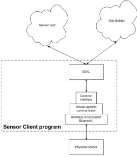
1.2.4.1 Sensor Client Program
A sensor needs a Sensor Client Program (SCP) to connect to SCMW. The SCP is the bridge for communication between actual sensors and SCMW. On the sensor side SCP communicates with the sensor through device-specific components such as device drivers. On the SCMW side SCP communicates with SCMW through Sensor Service Abstraction Layer (refer to section 3.5 for details).
environmental
[image:11.612.173.442.65.374.2]data Sensor sensor data Service processed
Figure 5 Structure of a Sensor Client Program
1.2.4.2 Computational Service
Computational Service is a special kind of sensor which does not take input from the environment. Instead, they take output of other sensors as their input, perform various computations on the data, and output the processed data finally. Since a Computational Service also produces a time-dependent stream of data it matches our definition of a sensor.
Figure 6 shows the data flow of how environmental data is transformed by processing data through a sensor and a Computational Service. The architecture of SCMW allows the data source to be assigned and reassigned dynamically.
Figure 6 Computational Service
1.2.5 Sensor Service Abstraction Layer (SSAL)
for connecting sensors to SCMW. Afterwards the sensor will be available for all applications right away.
Details of the SSAL are discussed in Section 1.5.2
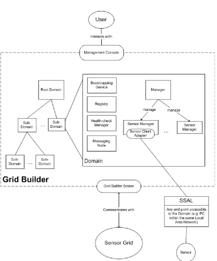
1.3 G r i d Builder
[image:12.612.91.530.182.710.2]1.3.1 An Overview of the Grid Builder Architecture
Figure 7 depicts the overall Grid Builder (GB) architecture. GB is originally designed for managing Grid-of-Grids. For this project, GB is extended to include the management of a
generalized sensor-centric grid of grids. Description of GB will focus on this specialized version. CGL-developed hpsearch is adopted and extended for this work [2].
The Grid which GB manages is arranged hierarchically into Domains. Each domain is typically, but not necessarily, a single PC which manages sensors which are closely related. Sensors can be deployed from any PC which is accessible from one of the domains. There can be only one root node in the grid known as the Root Domain. Each domain is started by its Bootstrapping.
Within each domain, there exist some basic components:
Managers and Resources
GB manages grids and resources through a manager-resource model. Each type of Resource which does not have a Web Service interface should be wrapped by a Service Adapter (SA). Each kind of SA is managed by a corresponding Manager.
Since our grid contains sensors, a Sensor Manager is responsible for managing sensors through
Sensor Service Adapters (SSA). Each SSA has its own set of defined Sensor Policy. This policy tells Sensor Manager how the SSA is to be managed, and defines the properties of the sensor bound to the SSA.
The Health-check Manager is responsible for checking the health of the whole system (ensures that the registry and messaging nodes are up and running and that there are enough managers for resources).
Bootstrapping Service
This service ensures that bootstrap processes of the current domain are always up and
running. For example, it periodically spawns a health-check manager that checks the health of the system.
Registry
All data about registered services and service adapters are stored in memory called Registry.
I I nstantlates 1 1.3.2 Significant Classes
1.3.2.1 Class Diagram
Resource Management
IWSMan CIIentl
I I
I I
ISensorP olicyl
I I
I I
jWSManPr ocessorl
I I Sensor Service I I Abstraction Layer r---1
: I :
1 jsensorCiicntServiceAdapterpensorScrviceAdapterl 1
ISensorCIIent Adapter1
----i I
L J
II\
I I
1 SensorCiient1 I
I
I I 1 I nsta
tlate
I I I \]; I
instantltes ISensorCIIentAdapterl
iSensorAdapterl -Instantiates IServlceAdapterl :
I I
-Instanti
ates
-- ---,- JSensorM
anager
I
: I I I I I I:
I_---:.:.-=--=--=--=--=--=--=--=--=--=--=--=-- -=-IResourceManagerl Domai n Managemen t Manager s
-instantiates
I
1 r
--manager tI _
,
I-Re-g-ste-re-dS-ub-D-om
-ai-nl
-f'rimaryHealt
hCheckerl
SAMModula RolgstorodSorvlce Rog storodServ ceAdapter
1--1---11 I I
1·, \V -onstantiates
i 1
I · Registry I ·
L--- -:,---'
jBootstrapS
ervicel
ISystemHealthCheckerl I Manager 11
1 Registry 1 'f
I I I I l -
-- lf--- - - - fSContext] L
Store
•i"• IL__-:L--_-_--_ l -_-_jf_-_--_-_-_-_--_-_!\-_-_- y---i._•te_s j_l -+---====
I L _
I ---:---1
: :
jMessagingNode l
._ _! , L J
r ----1 I I --, 7 MessageP«>Cef lor _,.., •
loc :
.2..
I I
I UserTools 1 I I I
t -ni
stantiates
r--=-I I
..s nd message
I
·in tantiates I L _I I
- -,
1 Brokelll'lode lf-_T_ra_n_sp_o_rtSubstr_at_e_
--1 I UsarUI I
I I --
-+send(in
loc:Universallo
cator) «send»
I I
I I
Messaging Layer
I
I
IFort<Daemon l
I
t--1
The diagram shows the class diagram of significant classes in GB. They are categorized into 5 main categories:
Messaging Layer
GB is built on top of a message-based architecture. All modules in GB such as BootstrapService, ForkDaemon, Managers, Registry and ServiceAdapters are standalone and communicate with one another by message passing. With this model, separate modules can be deployed as distributed services.
GB has a set of classes dedicated for message passing. Each module has a unique UUID and one or more UniversalLocator(s) (UL). UL provides all the information necessary to identify a module in the network, including transport type, host address, port and path. 4 transport types are supported: UDP, TCP, HTTP and NB. Each UL is responsible for message of one transport type.
TransportSubstrate is responsible for sending and receiving messages to and from a module. It automatically serializes the message content according to the transport type of destination. Once created, it spawns a thread which keeps waiting for incoming messages and notifies the associated MessageProcessor upon message arrival.
Modules which want to receive message should implement the MessageProcessor interface and associates itself with a TransportSubstrate. Important modules which implement this interface include BootstrapService, Registry, SystemHealthChecker, Manager,
ServiceAdapter and UserTools.
Communications between SensorManager and SensorServiceAdapters use the Web Service (WS) interface. WS in GB is built on top of this messaging layer.
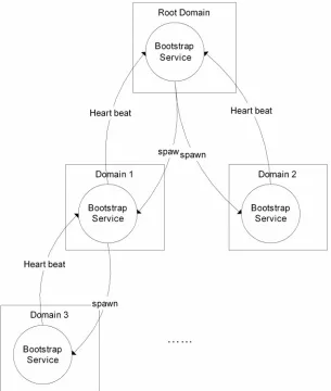
Domain Management
Domain management in GB is done by BootstrapService. Each domain has one BootstrapService which constantly communicates with the BootstrapServices of other domains. Each domain hierarchy contains one Root node. Each domain connects with at most one parent node and any number of child nodes. For now the hierarchy is defined using a configuration file
(mgmtSystem.conf).
Root
Heart beat Heart
spaw
Domain 1 Domain
Bootstrap Service
Heart
[image:17.612.91.396.69.429.2]Domain
Figure 9 Domain Management
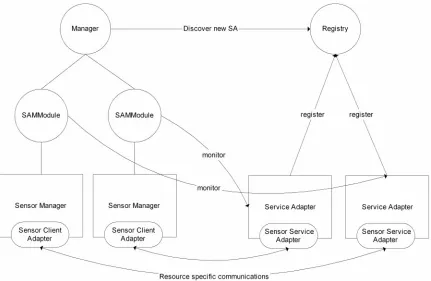
Managers
In GB there are two levels of managers. The lowest level is ResourceManager, which manages resource specific modules. For example, SensorManager is responsible for
managing a SensorServiceAdapter through the Web Service interface and performs operation such as sending policies to the adapters.
Manager Discover new SA
SAMModule SAMModule register register
Sensor Manager Sensor Manager Service Adapter Service
Sensor Client Sensor Client Sensor Service Sensor
Adapter Adapter Adapter
[image:18.612.92.523.68.349.2]Resource specific
Figure 10 Manager and Service Adapters
Resource Management
These classes are at the resource level, where resource specific tasks are performed. Each sensor is treated as a resource in GB, and each sensor has a corresponding client program (represented by SensorClient) responsible for interfacing the sensor with SCMW.
Sensor Service Abstraction Layer (SSAL) is the interface for connecting all types of sensor client programs with GB. The class diagram only shows part of SSAL which resides in GB. The whole SSAL involves classes of SXO as well.
Communication between resource managers (i.e. SensorManager) and Resources (i.e.
SensorServiceAdapter (SSA)) uses the Web Service (WS) interface for message passing. SSA therefore conforms to the WS “Put”, “Get”, “Delete” and “Create”. “Get” is used for getting SensorPolicy of the sensor and initiates connection with SG. “Delete” is used for disconnecting connection with SG.
Registry
Each domain has a Registry which maintains the state of the entire domain, such as the Universal Locator of every module, how many Service Adapters have been registered, the status and policy of each sensor, which SA is assigned to which Manager etc.
Registry can work with or without persistent storage. By default all information is stored in memory using hash tables. The user has an option whether to write all information to persistent storage so that it can be retrieved later on even if the domain is restarted. The persistent storage used is compliant to WS-Context specification [3].
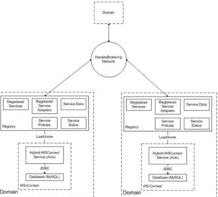
Figure 11 shows the overall architecture of the Domains, Registry and WS-Context modules in Grid Builder. To use WS-Context, an AXIS server and a MySQL server should be running in each domain for WS communication and storage. All domain related information in the Registry is stored in WS-Context and shared with other domains through NaradaBrokering’s topic-based publish-subscribe messaging service.
[image:19.612.94.526.274.664.2]Although the current implementation does not use WS-Context as a centralized database for service discovery, it can be easily enhanced to provide such service since the system is already WS compliant.
1.3.2.2 Class Description
This section provides brief description of each important class in GB.
Class name: MessageProcessor
Package name: cgl.hpsearch.core.transport
Description: Interface for classes which use GB's messaging layer to receive messages
Important interface:
processMessage()
Class name: MessagingNode
Package name: cgl.hpsearch.core.services.messagingNode
Description: Manages the GB's transport layer components (such as NB)
Important interface:
setBootstrapLocator(), startBrokerNode()
Class name: TransportSubstrate
Package name: cgl.hpsearch.core.transport
Description: Responsible for receiving and sending messages to and from MessageProcessor using different transport protocols
Important interface:
register(), send(), getUniversalLocatorForTransport(), close()
Class name: Message
Package name: cgl.hpsearch.core.messages
Description: Superclass of all types of messages in GB. Different types of message has different characteristics and serves different functions
Important interface:
getType(), getMessageId(), getTo(), getFrom(), getTimeStamp()
Class name: UniversalLocator
Package name: cgl.hpsearch.core.transport
Description: A locator which lets different modules to identify one another for messaging passing. Records the host, port, and transport type of a module
Important interface:
getHost(), getPort(), getPath(), getTransportType()
Class name: UserTools
Package name: cgl.hpsearch.core.services.user
Description: Responsible for forwarding different user operations (e.g. deploy sensors) to different modules in GB
Important interface:
getServiceData(), putServiceData(), retrieveStatus(),
Class name: UserUI
Package name: cgl.hpsearch.NaradaBrokering.usergui
Description: Graphical user interface of GB's management console
Class name: Manager
Package name: cgl.hpsearch.core.services.manager
Description: Manages all Resource Managers
Important interface:
processMessage(), startSAMManagementThread(), removeSAMManagementObject(), send()
Class name: SystemHealthChecker
Package name: cgl.hpsearch.core.services.manager
Description: Responsible for checking whether all modules are up and running in a domain
Important
interface: processMessage()
Class name: BootstrapService
Package name: cgl.hpsearch.core.services.bootstrap
Description: Responible for starting up all modules during domain initialization. Periodically spawns SystemHealthChecker and sending heart beat to parent domain
Class name: ForkDaemon
Package name: cgl.hpsearch.core.services.fork
Description: Responsible for creating different modules locally as processes
Important interface:
process()
Class name: SAMModule
Package name: cgl.hpsearch.core.services.manager
Description: Manages resources (sensors). Has one to one mapping to each Service Adapter and the corresponding Resource Manager.
Important interface:
send(), checkIfOwner(), getServiceData(), putServiceData(), spawnProcess(), sendMessage()
Class name: SensorManager
Package name: cgl.hpsearch.sensor
Description: Resource manager for managing SensorServiceAdapter
Important interface:
processMessage(), getServicePolicy(), putServicePolicy(), runService()
Class name: SensorClientAdapter
Package name: cgl.hpsearch.sensor
Class name: ServiceAdapter
Package name: cgl.hpsearch.core.services.sa
Description: Associated with a Resource Manager to manage the corresponding resource
Important
interface: start(), close(), publishData() Class name: SensorServiceAdapter
Package name: cgl.hpsearch.sensor
Description: Responsible for brokering the communication between a Resource Manager and sensor client program using Web Service
Important interface:
start(), close(), publishData(), handleSensorGridConnectionLoss(), setSensorProp(), processWxMGMT_Rename(), processWxfDelete(), processWxfPut(), processWxfCreate(), processWxfGet()
Class name: SensorClientServiceAdapter
Package name: cgl.hpsearch.sensor
Description: Responsible for brokering the communication between a Resource Manager and service sensor client program using Web Service
Important interface:
start(), close(), publishData(), handleSensorGridConnectionLoss(), setSensorProp(), sendControl(), setFilter(), subscribeSensorData(), unsubscribeSensorData(), processWxMGMT_Rename(),
processWxfDelete(), processWxfPut(), processWxfCreate(), processWxfGet()
Class name: SensorPolicy
Package name: cgl.hpsearch.core.policies
Description: Holds resouce specific policy, that is the property of a sensor
Important interface:
getType(), getSensorProperty()
Class name: WSManClient
Package name: cgl.hpsearch.wsmgmt
Description: Client interface for communicating with WSManProcessors (end points) using Web Service messaging
Important
interface: getMyEndPoint(), getServiceEndPoint(), setServiceEndPoint(), setWsEventingClient(), processMessage(), executeOneWay(),
executeRequestReply(), sendOut(), CreateAndMarshallMessage()
Class name: WSManProcessor
Package name: cgl.hpsearch.wsmgmt
Description: End point for receiving Web Service Message
Important interface:
1.3.3 Important Features 1.3.3.1 System Health Check
Every module in GB are deployed in a distributed manager and linked together by different network protocols. A health check system is therefore fundamental to ensure every modules are indeed deployed and working properly. GB performs periodic System Health Check (SHC) to ensure that every thing is up and running.
SHC can be divided into three stages:
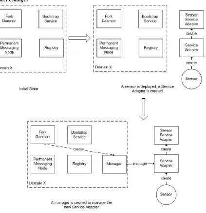
Initialization
Figure 12 System Health Check (SHC) Initialization
To start a new Domain X, a user has to execute a script to perform a Primary Health Check Sequence. This action creates a Permanent Messaging Node, which is responsible for
communication between all modules within a domain, and communication with other domains. After that, a Fork Daemon is created. Every module of Grid Builder (e.g. Registry, Service Adapters, Sensor Service Adapters etc.) is executed as a separate process in the operating platform. Fork Daemon is responsible for creating modules as separate processes.
After primary health check, the domain is now capable of receiving messages from other domains. The Bootstrap Service is launched when a message is received from the root domain. The Bootstrap Service is responsible for making sure that every module is up and running in a domain. It periodically spawns a System Health Checker to check the health of the system.
Detect Changes
Figure 13 Adding Service Adapter
When we introduce changes to the system, such as deploying a sensor, SHC automatically detects and reacts to the change. For example, a user deploys a sensor by starting the
Maintain System State
Figure 14 System Health Check (SHC) Maintaining System State
To make sure that every resource is up and running, each module periodically notifies its manager and the registry of its presence.
1.3.3.2 Classification Scheme
Classification defines all properties which are shared by all sensors supported by SCMW. Classification serves the following functions:
1. Allows GB to differentiate among different sensors for visualizing sensor’s policies
2. Defines what can be filtered
3. Allows meaningful visualization of sensor data at application side 4. Allows application to differentiate different sensors
Figure 8 shows the class diagram of classification. It can be divided into 3 categories:
Sensor Property
In order to introduce a new sensor to SCMW, the following properties have to be defined in class SensorProperty:
sensorId A Human readable ID for identification which does not have to be unique
groupId Sensors can be assigned to different logical groups for easier management. GroupId identifies the group
sensorType Textual description of the type of a sensor
sensorTypeId An integer which helps identifying the sensor type. Application has to compare this together with field sensorType to uniquely identify the type of a sensor
location Textual description of the location of a sensor, including street, city, state/province and country
historical Defines whether to archive collected sensor data in SG. Currently this feature is not implemented
sensorControl An array of integers which uniquely identifies each control message
controlDescription A string array of textual description of control messages. Should align with sensorControl array
userDefinedProperty A class which defines any user-defined properties specific for each type of sensor
SCMW comes with a set of predefined types. Class PredefineType contains information for generating predefined SensorProperty. UserDefinedProperty contains properties which are essential for the sensor but may not be common for all sensors (e.g. for deploying a RFID reader it needs the COM port for hardware interfacing). A set of user-defined properties for predefined sensors are implemented as subclasses of UserDefinedProperty.
For location, class PredefinedLocation contains a list of predefined mapping of city names and GPS latitude-longitude for easy visualization on a map.
Sensor Data
For each type of sensor, its data format is usually quite different from other sensors. In SCMW a class which extends SensorData should be created which defines how to decode and use data from a sensor.
Message Serialization
Each time before the property of a sensor is sent among modules (e.g. passing from
PredefinedType -instantiates SensorProperty
+sensorPropertyToXml()
-CITIES
NXTRobotData GpsData WiiRemoteData
[image:27.612.91.496.110.459.2]*
1.3.3.3 Filtering Mechanism
Overview -- Sensor
F11ter Query ''' '' I'' (1 ) -- --(3 ) --- --- -- ---'\ ' \ \ ' ' (5) \ I \
I '
\
' \ '
''(4)
' ") (1)
'
'' (1' )
(4)
' ' '''
(6) ' \ 'I\
\ I\ \
Sensor Grid
DOMAIN1
Registry (File 110) Registry (File 1/0)
\ ' ' '
DOMAIN3
Registry (File 110)
---
Step 1. Sensor Grid looks for a registry for filler query.Publish a request message on a common topic or all registries. the registry which replies the eMiest will be chosen. (1) GET_GRID_BUILDER_SERVICE_POLICY
(2) GET_GRID_BUILDER_SERVICE_POLICY_RESPONSE
Step 2. Sensor Grid sends a Sensor Filter Query to the chosen registry (say registry in Domain1) (3) FILTER_SERVICE_POLICY_QUERY
(/oca/=false) (Note:localmeans localsearch only]
Step 3.Reg1stry publishes a filter query to all other registries
(4) FILTER_SERVICE_POLICY_QUERY (loca/=tnue,with timestamp) [Note:timestamp is a unique Identifier for the query]
immediately through the umque topic of the request registry. (5)
aggregates the responses (identified by timestamp) and send back to Sensor Grid (6) FILTER_SERVICE_POLICY_QUERY_RESPONSE (loca/=false)
Figure 3-14 SCGMlv.IS sensor filtering mechanism in a distributed architecture
Request
Response
At the application standpoint filtering is essential for retrieving only the required sensors from a possibly huge sensor pool. Filtering is done based on the SensorProperty of each sensor, which is defined according to based on rules in classification.
Defining a Filter
Applications have to define filtering criteria according to their UDOP requirements. The criteria are encapsulated in a SensorFilter object. A SensorFilter is composed of a set of properties defined in SensorProperty connected with Boolean “and” or “or” operators. Please refer to section 3.3.3.2 for the definition of SensorProperty. Given that a list of sensor properties in a sensor filter are connected together with the “and” operator, only sensors which have properties with exact match in string comparison with ALL the properties defined in the filter should get through. Similarly sensors which have
properties with exact match in string comparison with ANY of the properties defined in a sensor filter with sensor properties connected together with the “or” operator should get through.
The list of “and” and “or” sensor properties are represented as a 2D string array in SensorFilter. For example, if someone wants to get a list of SAID which have policy ((sensorType=GPS and location="Hong Kong") or (sensorType=RFID and location="New York" and historical=true)), set the filter like this:
SensorFilter filter=new SensorFilter(); String[][] comp=new String[2][]; comp[0]=new String[2]; comp[1]=new String[3];
comp[0][0]="sensorType=GPS"; comp[0][1]="location=Hong Kong"; comp[1][0]="sensorType=RFID"; comp[1][1]="location=New York"; comp[1][2]="historical=true"; filter.setOrComparison(comp);
Data Flow
Filtering is done in three stages:
Application to SG
A filter query request is initiated from the application. For each filter query, fields which exist in SensorProperty can be combined using the “and” or “or” operator to form a query string. This string is then sent to SG.
SG to GB
SG forwards the request to GB. At this stage, GB searches through the registry of all domains and aggregates the unique id of sensors which match the query in a response message. The response message is then sent back to SG. SG periodically checks if the filter request from application changes. If it does, the application is notified in the same manner.
SG to application
SG releases the resources (e.g. unsubscribe sensor's NB topic) used by sensors which are no longer in the list, and initiates resources for new sensors. Then SG notifies the client for all changes made.
ManagementSystem udp:
1 :
PrimaryHealthChecker
1 .
4 4 3
ForkDaemon
1.3.4 Detailed Description
In this section, message flow of various operation of SG will be discussed at Class level using UML collaboration diagrams.
1.3.4.1 Starting a Domain
The following diagram shows the events happening when a domain is started.
Figure 3-15 Event flow when starting a sensor grid domain
1. A user starts the domain by executing “runPrimaryHealthCheck.bat”
2. ManagementSystem.BootStrap() is called to initialize all system properties, environment variables and various user-defined properties from configuration files
3. Send a PingRequestMessage to the expected locator(s) of messaging node(s) registered in configuration files. If any messaging node does not respond with PingResponseMessage within 5 seconds, go to 3.1. Otherwise go to 4
3.1. For each messaging node not responding, send a request to ProcessRunner to start a PermanentMessagingNode process
3.2. ProcessRunner starts the messaging node process
3.3. Spawns a thread which continuously monitors the presence of itself by using udp messages (ping request and response). Starts a BrokerNode (NB) according the configuration provided by configuration file (defaultMessagingNode.conf) 4. Send a PingRequestMessage to the expected locator(s) of ForkDaemon(s) registered in
configuration files. If any ForkDaemon does not respond with PingResponseMessage within 5 seconds, go to 4.1. Otherwise go to 5
4.1. For each ForkDaemon not responding, send a request to ProcessRunner to start a ForkDaemon process
4.2. ProcessRunner starts the ForkDaemon process
Thread::ParentBootstrapRegistr ation
3
1
RegisteredSubDomain
n ForkDaemon
:3
Runner
BootstrapService::SubDomain ForkDaemon::SubDomain Proceed to Normal
Check Sequence (Stage
1.3.4.2 Starting BootstrapService of a Domain
[image:33.612.98.517.138.379.2]When a domain is start, it undergoes the following Bootstrap sequence.
Figure 3-16 Starting BootstrapService of a Domain
1. Initialize the Bootstrap node from config file, including domain hierarchy and locators of ForkDaemons, RegistryForkDaemon, MessagingNodeDaemons. NB transport is initialized for NB communications with other domains
2. If the current domain is not a leaf node, register all sub-domains locally
3. If the current domain is not the root node, runs a thread that periodically sends a RegisterRenewMessage to the BootstrapService of its parent telling this domain’s BootstrapService is running. If the domain is a leaf node, go to 3.1. Else go to 4 3.1. Starts a thread that periodically spawns a SystemHealthCheck process for each
registered ForkDaemon.
3.2. Spawns a SystemHealthChecker process by sending a ForkProcessMessage to ForkDaemon with the “healthcheck” parameter
3.3. ForkDaemon spawns the Manager process with the “healthcheck” parameter. 3.4. Manager starts the SystemHealthChecker thread. System undergoes Normal Health
Check Sequence (Please refer to section 3.3.4.3 for details). BootstrapService waits 10 seconds for the reply from SystemHealthChecker
3.5. The replied status from SystemHealthChecker is either COMPLETE, UNKNOWN or RUNNING. Repeat 3.1 after some sleep
4. If the node is not a leaf node, spawns a thread that periodically checks the status of ALL RegisteredSubDomains (RSD). Under the Health Check mechanism, all
RegisteredSubDomains are supposed to send a RegisterRenewMessage to its parent. 5. If no RegisteredRenewMessage is received from a SubDomain within a specified amount of
WSContextStore
usSender
n b 2
: b
:
BootstrapService SystemHealthChecker
Proceed to Normal Check Sequence (Stage
1.3.4.3 Normal Health Check Sequence (Stage 1)
[image:34.612.95.464.151.487.2]System Health Check has a number of stages. During the first state, Bootstrap Service checks if the Registry is present. If not, creates a Registry process using the Fork Daemon.
Figure 3-17 Normal Health Check Sequence (Stage 1)
1. After NB transport is initialized, a thread is started that automatically kills the the health checker if it is still running after 60 seconds
2. A thread is started that automatically notifies the BootstrapService at an interval of 2 seconds that the health checker is running
3. Checks if there is a Registry running in the domain by sending a RegistryQueryMessage to the defined Registry locator. If a RegistryQueryResponse message is received, go to 4. If no, go to 3.1
3.1. Try spawning a Registry process by sending a ForkProcessMessage to ForkDaemon. Max retries = 5. After each retry, repeat 3. If number of retries reached, health checker terminates with abnormal exit status
Refer to Service Adapter
ForkDaemon
n
3 . b
1 : 1
b
1 n
nb: 2
SystemHealthChecker BootstrapService
3.2.1. Registry asks PersistantStoreFactory for an instance of WSContextStore, which is responsible for storing and retrieving settings from persistent storage (e.g. relational database)
3.2.2. WSContextStore is initialized by making connections to various components defined in WSContext and removing all previous entries (e.g. registered service adapters, service policy, service status etc.). If any errors occur during initialization, go to 3.3 and everything will be saved in memory
3.2.3. Registry loads all settings from WSContextStore to in memory hash tables 3.3. Registry initializes NB transport by subscribing to two topic – one common to all
registries and one uniquely identify itself. Registry spawning process has been finished. Go back to 3
4. Registry responds to SystemHealthChecker with the number of managers and service adapters expected in the domain.
5. System now enters health check stage 2. Proceed to section 3.3.4.4 .
1.3.4.4 Normal Health Check Sequence (Stage 2)
[image:35.612.91.374.364.636.2]System Health Check has a number of stages. During the second stage, Bootstrap Service checks if enough Managers are spawned as defined in the configuration file.
Figure 3-18 Normal Health Check Sequence (Stage 2)
Registry
1 n n n
.
6 b : b :
:
b 7 . 3
n
4
Manager
1.1. For each Manager lacking, create a Manager process without the "healthcheck" parameter sending a ForkProcessMessage to ForkDaemon
1.2. ForkDaemon creates the Manager process
1.3. Request system configuration from BootstrapService, including locator of Registry, ForkDaemon
1.4. BootstrapService replies with system configuration
1.5. Initialize NB transport support. Starts a SAFinderThread which keep sending FindSAToManageMessage to Registry requesting corresponding ServiceAdapters to manage. If no reply from Registry, the request is repeated periodically at 2 second interval. For details of this part, please refer to section 3.3.4.6 .
1.6. The Manager periodically sends a RegisterRenewMessage to the Registry to notify its presence
2. SystemHealthChecker sleeps for 10 seconds to allow any pending processes to instantiate. Then it checks whether all expected processes are up and running. If yes, it sends a SystemHealthCheck message to BootstrapService, notifying that System Health Check is completed and then terminates itself. Otherwise, it checks the system’s health from stage one again (section 3.3.4.3 ) and tries spawning the process(s) missing
1.3.4.5 Registered Service Adapter Health Check Sequence
[image:36.612.99.456.380.638.2]SAMModule notifies the Service Adapter which Manager it should send heart beat messages to
Figure 3-19 Registered Service Adapter (RSA) Health Check Sequence
1. Checks if the associated RSA has sent a HEARTBEAT within the specified interval. If yes, sleep for a while and do 1 again. Else go to 2
3.1. Sends a HEARTBEAT message to the RSA and wait. If RSA replies within a time limit, sleep for a while and do 1 again. Else go to 4
4. Ask ResourceManager(RM) whether to release the RSA.
5. If RM knows that the RSA is up and running, go to 7. Else go to 6 6. Notifies the Manager that the associated RSA is unreachable.
6.1. Sends a UPDATE_SA_STATUS message to the Registry, saying that the RSA is UNREACHABLE
6.2. Registry performs status update
7. Re-register with the RSA by sending a HEARTBEAT to it. Sleep for a while and do 1 again
1.3.4.6 Service Adapter Discovery
[image:37.612.95.522.283.636.2]System Health Check checks if every Service Adapter is associated with its Manager.
Figure 3-20 Message flow of service adapter discovery in a sensor grid
1.1. Registry retrieves the information of a list of Registered Service Adapters from WSContextStore
1.2. Registry replies with ServiceAdapterToManageMessage to the Manager if there is at least one ServiceAdapter (SA) which does not have an associated SAMModule. Status of the SA is set to MANAGED. At most one SA will be replied for each request. If there are no SA to manage, the Manager shutdowns itself.
2. For each SA, the Manager creates a SAMModule which manages the SA. 3. SAMModule creates a specific type of ResourceManager specified in the SA (in
ServiceAdapterInfo), and starts the ResourceManager in a new Thread. For sensors, a SensorManager (ResourceManager for sensors) is instantiated
4. A SensorClientAdapter is instantiated. The SAMModule of SensorManager is passed as message sender and the locator of the associated SA is set as message destination
5. SAMModule starts a HeartBeatCheckerThread that periodically checks 1) if SA is up and running 2) if SA is still associated with this SAMModule (possibly taken control by other Managers)
6. Sends a setHeartBeatLocator message to SA to associate the SA with this SAMModule and tells SA the locator of Manager which heart beat messages should be sent to. Afterwards, HeartBeatCheckerThread enters the loop of SA health check (please refer to section 3.4.5 - Registered Service Adapter Health Check Sequence)
7. Sends a GetServicePolicyMessage to SAMModule, request for the policy of the associated resource (i.e. sensor)
8. Forwards the request to SensorManager by calling getServicePolicy() 9. Invokes the associated SensorClientAdapter’s getServicePolicy()
10. Sends a Wxf_Get message to the associated SensorServiceAdapter through SAMModule 11. Wraps the message with ServiceSpecificMessage and forwards it to the associated
ServiceAdapter
12. Invokes processSOAPMessage of the associated SensorServiceAdapter (SSA)
13. If SensorPolicy has been defined, serialize it with PolicyManager. Otherwise, just create an empty message
14. If this is the first time SSA is assigned to a Manager, starts a SensorGridBroker which notifies SG of its presence
15. Sends back a response message with the serialized policy (if any) 16. Forwards the response to SAMModule
17. Forwards the response to Manager 18. Forwards the response to Registry
19. Updates the policy of the SA to the corresponding RSA in Registry. If persistent storage is used, go to 19.1; otherwise, go to 19.2
6
ForkDaemon GPSManager
5
nb:4 Registry ServiceAdapter
3 :
n
b :
1
UserUI DeployDialog
1.3.5 Deploying and Disconnecting sensors 1.3.5.1 Deploying a GPS Sensor
[image:39.612.96.525.164.404.2]The message flow of deploying any sensors in a sensor grid is similar. For illustrative purposes, the message flow of deploying a GPS sensor is shown in Figure 3-21.
Figure 3-21 Deploying a GPS Sensor
1. User chooses a domain and clicks “deploy” 2. UserUI creates a DeployDialog
3. User defines the policies of the sensor and clicks “ok”. A ForkProcessMessage is sent to the Registry to spawn a sensor client program
4. The message is forwarded to BootstrapService 5. The message is forwarded to ForkDaemon
6. ForkDaemon starts the type of sensor client program according to policy defined. Suppose user needs a GPS sensor. ForkDaemon creates a GPSManager process
7. Creates an instance of SensorPolicy according to the type of sensor and classification. 8. Creates an instance of SensorAdapter, passing in a SensorAdapterListener,
SensorGridControlListener and SensorPolicy
9. Creates an instance of ServiceAdapter (SA) with parameters “saType=cgl.hpsearch.sensor.SensorServiceAdapter” and “manType=cgl.hpsearch.sensor.SensorManager”
10. Subscribes to the SA's own NB topic. Instantiates a SensorServiceAdapter according to “saType”
11. Sends a RegisterRenewMessage to the Registry
UserUI
p : u
d d
1 p 1
UserTools
1
ServiceAdapter SensorManager
nb:
7 nb:
SensorServiceAdapter
1
Stops the Client
13. Subscribes to a new NB topic according to the returned instanceId. Starts a new thread responsible for sending RegisterRenewMessage (heart beat) to the Registry. SA enters a state that keep tracking if NB connection is down. If yes, try to reconnect
14. GPSManager makes physical connection to the sensor, and starts a WatchDog which monitors the physical connection
After the new SA is registered in the registry, the Normal Health Check Sequence for Managers (Stage 2) will discover the new SA is not yet managed. A Manager will be assigned to it. For details please refer to session 3.3.4.4 .
1.3.5.2 Disconnecting a Sensor
[image:40.612.92.420.293.606.2]There are two ways to disconnect a sensor. The first way is to terminate the Sensor Client Program explicitly. The second way is to do it through GB’s management console. The diagram below shows the message flow of disconnecting a sensor through GB’s management console.
Figure 3-22 Disconnecting a sensor by using the Grid Builder management console
1 User selects a sensor in GB’s management console and clicks “Stop”. UserUI invokes sendRunMessage() of UserTools
3 Registry locates the Manager of the corresponding RegisteredServiceAdapter and forwards the message to it
4 Manager locates the corresponding SAMModule responsible for managing the ServiceAdapter and forwards the message to it
5 SAMModule forwards the message to the associated SensorManager
6 SensorManager forwards the message to the associated SensorClientAdapter
7 SensorClientAdapter sends a Wxf_Delete message to the associated SensorServiceAdapter through SAMModule
8 Wraps the message with ServiceSpecificMessage and forwards it to the associated ServiceAdapter
9 Invokes processSOAPMessage of the associated SensorServiceAdapter (SSA)
10 SensorServiceAdapter stops the sensor through SSAL. For details please refer to section 3.4.4.9
11 An error report message is replied indicating if any error exists 12 Forwards the reply to SensorClientAdapter
13 Wraps the reply with a RunServiceResponse message, and sends it back to Registry through SAMModule
14 Forwards the response to Manager 15 Forwards the response to Registry
16 Registry does not do anything to the response
1.4 Sensor Grid
Figure 3-23 Overall Architecture of Sensor Grid and related Modules
1.4.1.1 Message Brokering
It enables the flow of messages among all parties including: 1. sensor data
2. sensor control messages 3. filtering requests and results 4. changes of sensor status 5. sensor policies
The following modules are essential for communication among the parties.
GXO
GXO is a messaging layer which uses NaradaBrokering (NB) for message passing. It has the following characteristics:
1. supports a lot of transport layer protocols, including tcp, niotcp, udp, http, https and so on
2. abstracts messages into byte, text and object messages which performs automatic message serialization and de-serialization
3. uses a topic-based, publish and subscribe model which eliminates the need for identifying end points explicitly
4. allows flexible construction of brokering network
With the use of GXO, messages can propagate to the destination with minimum programming effort.
SXO
SXO is a layer built on top of GXO. It is the internal API which facilitates communications between sensors, application clients and SG. It handles the connection
and disconnection of both sensors and application in a seamless and fault-tolerant manner. It contains logic and libraries for both Application API and SSAL to communicate with applications and sensors respectively.
Application API
All kinds of applications communicate with SCMW through the same API. The Application API provides libraries for applications to:
1. access data and metadata of sensors 2. send control messages to sensors 3. notified for change of sensor status 4. send filter requests to SCMW
These actions are done with the help of the following modules in the API:
Application Client Broker
Sensor Change Listener
Interface used by application clients to receive messages from SG such as sensor status change.
Sensor Data Listener
Interface used by application clients to receive data from sensors.
To support different applications, Application API in turn communicates with SCMW through SXO. For more detailed description of Application API, pleased refer to section 3.5.
SSAL
All sensors communicate with SCMW through SSAL. Remember each sensor has a corresponding Sensor Client Program (SCP) to communicate with SCMW. SSAL provides libraries for sensors to do the following through SCP:
1. publish data
2. receive control messages
3. receive stop request from SCMW 4. subscribe to data of another sensor
5. listen to status change of subscribed sensor
Not all kind of sensors have to use all functionalities listed above. Remember sensors can be further classified into normal sensors and Computational Service. In fact these two categories utilize different subset of classes in SSAL. Some of the important modules of SSAL are listed below:
Sensor Client Adapter
An interface for publishing data
Sensor Data Listener
An interface for listening to data from subscribed sensors. Used by Computational Service
Sensor Adapter Listener
An interface for listening to stop requests from SCMW. The SCP should terminate upon receiving the request
Sensor Change Listener
An interface for being notified when the subscribed sensor has any status change. Used by Computational Service
Sensor Grid Control Listener
An interface which sensors listen to control messages
Application X Application Y
Sensor
Table A_S Table Application Sensors Sensor
X S1, S2, S4 S1 Policy Y S3 S2 Policy S3 Policy Table
S4 Policy Application
S5 Policy X Criteria
Y Criteria 2 Table Online S1, S2, S3, S4,
S1 S2 S3 S4 S5 Sensors
1.4.1.2 Application Management
In SCMW, SG is responsible for maintaining the state of the whole system. For each deployed sensor and running application, SG caches down their presence and their relationships with one another. The figure below shows a scenario which 2 applications and 5 sensors are connected to SG. The four tables shows how SG maintains the state of the system, they include:
A list of online sensors (Table S)
SG maintains a list of online sensors which dynamically changes with the deployment status of the sensor
Application to sensor mapping (Table A_S)
Each application needs a different set of online sensors according to its filtering criteria. This is to make sure that sensors which are not concerned by the application do not hold unnecessary resources. A table is maintained to remember this mapping
Application to filter mapping (Table S_F)
Each application has its own filter, which are the criteria that define which sensors are needed by the application. The filter can be modified by the application at any time.
Sensor to sensor policy mapping (Table S_P)
Sensor Policies defines the characteristics of sensors. It is defined by Grid Builder before deployment. The sensor policy is obtained from GB and cached whenever a sensor is being deployed.
change 1.4.2 Sig nificant Classes
1.4.2.1 Class Diagram
r---ClientGrdl Broker
f:11entGrldChangeListener sxo
I
Application API
AppletV
CMaln /. 1
I
' GXO
sensoriCi."Hash"seic'ii.nioa lste. er> I ' l
HashMap
--- - -instantiates
l.;in$,taiatesnt I I I
---... SGCIIentvlew I i ClicntGridOataUstener I I 1 I i
----r I I
1
---
T-sensorld I
l--- I
HeshSel : II ensorCiientGridBroker
--- -- --- - -contror l jsGsensorView J---- _: !SensorGridBroker I -+ --r sensortd I I I I
--- .,_ ----I
I SGResou rce r---
--I
SensorGrldContr
ollistencr
I I I
SensorAdapte
rListencr
ensorCIIen tAdapter SensorAdapter
I I I I
I
t
-I SSAL
I
1 --- --- --
---SensorCIIent
'---- sensorld
r --- M--- ---prldBullder
Sensor Grid
FiltetfJi
onitOf
-pol
cies
I" "'
-filte
rs !J.·client senS«s
--- Ci· j J,.-:'sn
ls nso_rld, Sensoof>ollcy I
Hash
Map
l r-i.id_:s
-ensolile-r
1
HashMap
nsorld
I
L ---
HashSet
l e-nt-_ld,-Ha-sh-S-et<-se-ns -ofi-d>-I
HashMap
Figure 3-25 Class Diagram of SG, Sensor and Application Client
1.4.2.2 Class Description
This section provides brief description of important classes of SG and SSAL.
Class name: ClientGridBroker
Package name: com.anabas.sensorgrid.client
Description: Part of the Application API. Provides the interface for external applications to communicate with SG and sensors. Notifies GXO for application joining
Important interface:
setFilter(), sendControl(), subscribeSensorData(), unsubscribeSensorData()
Class name: ClientGridChangeListener
Package name: com.anabas.sensorgrid.client
Description: Part of the Application API. Provides the interface for receiving sensor status change due to sensor deployment, disconnection and filtering
Important
interface: handleSensorInit(), handleSensorChange() Class name: SGClientView
Package name: com.anabas.sensorgrid.session.sharedlet
Description: Part of SXO. Contains most of the application-client-side logic for the communication with SG and sensors, such as receiving sensor
change, sending filter to SG and sending control messages to sensors. All NB topic and streams are handled here
Important interface:
setChangeListener(), startConnection(), subscribeSensorData, unsubscribeSensorDawta(), setFilter(), sendControl()
Class name: ClientGridDataListener
Package name: com.anabas.sensorgrid.client
Description: Part of the Application API, responsible for notifying the application on sensor data arrival. If the application clients wants to receive data from a particular sensor, it has to create a ClientGridDataListener for that sensor. Afterwards, the listener will be notified for data arrival
Important interface:
handleSensorData()
Class name: SGSensorView
Package name: com.anabas.sensorgrid.session.sharedlet
Description: Part of SXO. Contains most of the sensor-side logic for the communication with applications, such as publishing data and receiving control messages. All NB topics and streams are handled here
Important interface:
Class name: SensorGridBroker
Package name: com.anabas.sensorgrid.sensor
Description: Part SXO. Brokers communication between SSAL, SG and sensors. Notifies GXO for sensor deployment and disconnection
Important publishData(), close()
interface:
Class name: SensorClientGridBroker
Package name: com.anabas.sensorgrid.sensorclient
Description: Part of SXO. Brokers communication between SSAL, SG and service sensors. Notifies GXO for sensor deployment and disconnection
Important interface:
publishData(), sendControl(), setFilter(), subscribeSensorData(), unsubscribeSensorData()
Class name: SensorGridControlListener
Package name: com.anabas.sensorgrid.sensor
Description: Part of the SSAL. Provides the interface for receiving control messages
Importan t
interface:
handleSensorControl()
Class name: SensorAdapter
Package name: com.anabas.sensor.sensoradapter
Description: Part of SSAL. Provides the interface for sensors to publish data to applications
Importan t
interface:
publishData(), start(), close()
Class name: SensorAdapterListener
Package name: com.anabas.sensor.sensoradapter
Description: Part of SSAL. Responsible for receiving termination commands from GB
Importan t
interface:
handleSensorConnectionLoss(), handleSensorStopRequest()
Class name: FilterMonitor
Package name: com.anabas.sensorgrid.session.sharedlet
Description: Actually this is an inner class of SensorManager responsible for periodic checkup to update the set of sensors for each application according to their corresponding filter
Important 0
Package name: com.anabas.sensorgrid.session.sharedlet
Description: Part of SG. Contains the logic for managing all connected applications and sensors. Maintained HashSets and HashMaps to cache sensor policies, applications' filters and sets of sensors mapped to each application.
Important interface:
addSensor(), removeSensor(), addClient(), startClient(), removeClient(), setFilter()
Class name: SGSessionLogic
Package name: com.anabas.sensorgrid.session.sharedlet
Important interface:
through SensorManager for every connections and disconnections of sensors and applications (notified by GXO)
userJoined(), userLeft()
Class name: AppletVCMain
Package name: com.anabas.sharedlet.appletframework
Description: Part of GXO. Resides at client side (applications and sensors) for allocating and releasing resources
Importan t
interface:
allWindowsClosed()
1.4.3 Important Features
1.4.3.1 NB Data Flow and Topic Management
Communication between applications, sensors and SG relies on NaradaBrokering (NB) for communication. This section provides a brief description of data flow between the three parties.
Each sensor creates a topic for publishing data and a topic for subscribing control messages. When an application is notified by SG for a new sensor, it subscribes to the two topics of the corresponding sensor directly for receiving data and publishing control messages.
Stream NB Topic
T_SG application/x-sharedlet-sensorgrid/private
T_CY application/x-sharedlet-sensorgrid/client/CY
T_CX application/x-sharedlet-sensorgrid/client/CX
[image:52.612.94.521.82.560.2]T_S1_Data application/x-sharedlet-sensorgrid/sensordata/S1 T_S1_Control application/x-sharedlet-sensorgrid/sensorcontrol/S1 T_S2_Data application/x-sharedlet-sensorgrid/sensordata/S2 T_S2_Control application/x-sharedlet-sensorgrid/sensorcontrol/S2
1 2 3
SGSessionLogic SensorManager GridBuilderBroker
4
Thread::FilterMonitor 1.4.4 Detailed Description
In this section, message flow of various operation of SG will be discussed at Class level using UML collaboration diagrams.
1.4.4.1 Sensor Grid Startup
Sensor Grid starts a perpetual session.
Figure 3-27 A Sensor Grid startup sequence
1 An instance of SGSessionLogic is created by the framework
2 An instance of SensorManager is created, which is responsible for handling sensor- application interaction
3 An instance of GridBuilderBroker is created, which is responsible for obtaining SensorPolicy from Grid Builder
SensorGridControlListener
SensorClient SensorServiceAdapter
1 3
SensorAdapter ServiceAdapter
7 8
SGSessionLogic SensorManager
Thread::FilterMonitor HashMap::id2Policy
Periodic filtering
1.4.4.2 Deploying a Sensor
[image:54.612.93.439.161.464.2]When deploying a sensor through the Grid Builder, sequencecs of messages are invoked to enable the management of deployed sensors as well as mechanisms to filter sensors based on sensor policies. Message flow when a sensor is deployed through Grid Builder is illustrated in Figure 3-28
Figure 3-28 Message flow when depolying a sensor through the Grid Builder
1 The sensor client program instantiates SensorAdapter when it is started by Grid Builder 2 SensorAdapter instantiates ServiceAdapter, which is later on managed by Grid Builder 3 Service Adapter instantiates SensorServiceAdapter, which resides in SSAL for
communication with SensorManager of Grid Builder
4 SensorServiceAdapter instantiates SensorGridBroker, which communicates with Sensor Grid
5 SensorGridBroker initializes all parameters needed for the sensor to join the Sensor Grid, including sensorId and system configuration, then instantiates AppletVCMain with all the parameters which tells the framework to prepare for a sensor client. Sleep for 5 seconds. 6 A SGSensorView is instantiated by the framework, which is responsible for message
passing between application clients, sensors and Sensor Grid. A unique NB stream is created for publishing sensor data and another one created for subscribing control
messages. SensorGridBroker obtains a reference to SGSensorView from the framework and registers the SensorGridControlListener