This content has been downloaded from IOPscience. Please scroll down to see the full text.
Download details:
IP Address: 139.86.2.14
This content was downloaded on 07/03/2014 at 05:57
Please note that terms and conditions apply.
Analysis of Camera Parameters Value in Various Object Distances Calibration
View the table of contents for this issue, or go to the journal homepage for more 2014 IOP Conf. Ser.: Earth Environ. Sci. 18 012039
(http://iopscience.iop.org/1755-1315/18/1/012039)
Analysis of Camera Parameters Value in Various Object
Distances Calibration
Ahmad Razali Yusoff1, Mohd Farid Mohd Ariff1, Khairulnizam M. Idris1, Zulkepli Majid1, Halim Setan1, Albert K. Chong2
1UTM-Photogrammetry and Laser Scanning Research Group, Infocomm Research Alliance (IcRA)
Faculty of Geoinformation and Real Estate Universiti Teknologi Malaysia.
2Faculty of Engineering and Surveying, University of Southern Queensland, Australia
E-mail: [email protected]
Abstract. In photogrammetric applications, good camera parameters are needed for mapping purpose such as an Unmanned Aerial Vehicle (UAV) that encompassed with non-metric camera devices. Simple camera calibration was being a common application in many laboratory works in order to get the camera parameter’s value. In aerial mapping, interior camera parameters’ value from close-range camera calibration is used to correct the image error. However, the causes and effects of the calibration steps used to get accurate mapping need to be analyze. Therefore, this research aims to contribute an analysis of camera parameters from portable calibration frame of 1.5 × 1 meter dimension size. Object distances of two, three, four, five, and six meters are the research focus. Results are analyzed to find out the changes in image and camera parameters’ value. Hence, camera calibration parameter’s of a camera is consider different depend on type of calibration parameters and object distances.
1. Introduction
Camera calibration is one of the important processes in photogrammetric application. Camera calibration is the initial step in many machine visions and photogrammetric applications involved [1]. Lens distortion is one of the major factors affecting the camera calibration [2]. Accurate camera calibration and orientation procedures are necessary prerequisite for the extraction of precise and reliable 3D metric information from the image [3]. Digital cameras which currently used in UAV mapping has received great interest from the remote sensing and aerial surveying communities because it is a low cost equipment [4]. Unfortunately, most of digital cameras used in civilians UAV are not manufactured metric devices; therefore, if they are to be used in precision mapping applications it is crucial that they are repeatedly calibrated to assess current interior orientation parameters [5].
Many techniques and some studies concerning calibration have been presented in the last few years [6]. There is a lot of literature on the calibration of digital cameras that has been published, such as [7,8], on general investigations [9,10,11], low- cost digital cameras [12,13,14], behaviour of interior orientation parameters [14,15], and accuracy aspects[16]. In order to study about the principles of camera calibration and the changes of camera parameter’s value, the camera calibration with various object distances need to be analyzed.
8th International Symposium of the Digital Earth (ISDE8) IOP Publishing IOP Conf. Series: Earth and Environmental Science18(2014) 012039 doi:10.1088/1755-1315/18/1/012039
Content from this work may be used under the terms of theCreative Commons Attribution 3.0 licence. Any further distribution of this work must maintain attribution to the author(s) and the title of the work, journal citation and DOI.
2. Camera Calibration
Camera calibration methods involve the estimation of parameter values that provide the ability to accurately infer information of the real world from single image [15]. A camera is considered calibrated if the principal distance, principal point offset and lens distortion parameters are identified [3]. Camera calibration methods are divided into traditional calibration and self-calibration methods. The traditional approaches take advantage of a calibration pattern with precisely known structure. The parameters of the camera model are determined by conjugate points in the image space [17,18,19]. The self-calibration method utilizes correspondences between small numbers of points in two or more views of a moving camera [20].
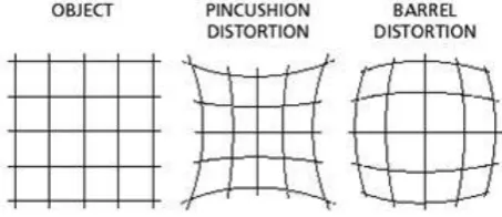
[image:3.595.173.400.245.343.2]According to [4], there are two types of distortion: (1) radial distortion, which is symmetric from the principle point (pincushion and barrel distortion), and (2) tangential or decentering distortions. Figure 1 shows the types of radial lens distortion.
Figure 1. Radial lens distortion
3. Calibration Technique
The calibration procedure used in this experiment is the same as for other camera calibration procedure used in photogrammetry application. For example, [7,9] discussed about close-range photogrammetry while [21,22] reviews about aerial photogrammetry using Unmanned Aerial Vehicle (UAV) platform.
3.1. Calibration Frame
The calibration frame used in this experiment is 1.5 × 1 meter of portable calibration frame as shown in Figure 2. This type of frame is used in the experiment because it can be used for calibrating in a long distance as preferred in the experiment which is within six meters object distance.
Figure 2. Medium portable calibration frame Figure 3. Rectro-target
This calibration frame is different from the normal close-range camera calibration. The concept of this experiment is to identify the trend of camera parameter’s value within various object distances. The targets markers used in the calibration frame are retro-target point with 10 cm diameter size each of them (Figure 3). The retro-targets marker are highly reflective target which are specially made for precise automated digitizing using computer software [24]. This kind of target is easy to process by using Australis software that is used in this experiment. The specification of this calibration frame is suitable to calibrate in a long distance as done by [23], but it depends on the processing work to point the retro-target marker.
8th International Symposium of the Digital Earth (ISDE8) IOP Publishing IOP Conf. Series: Earth and Environmental Science18(2014) 012039 doi:10.1088/1755-1315/18/1/012039
[image:3.595.125.428.515.626.2]3.2. Digital Camera and Processing
Digital camera used is DSLR Sony F2F. The pixel size of the camera is 0.002 mm. Figure 4 below shows the digital camera used. Figure 5 shows Australis (version 6.01) software that used in this experiment. Australis software is common software used by photogrammetry user and it also can give accurate measurement and suitable for long range object distances.
Figure 4. Digital camera Sony F2F Figure 5. Australis software
3.3. Laboratory Calibration
[image:4.595.234.524.352.506.2]The experiment is done at Photogrammetry and Laser Scanning Research Group (PLS-RG) lab room at Universiti Teknologi Malaysia (UTM). A big room is needed to occupy the six meter calibration frame and the digital camera station. Figure 6 and 7 below show the technique used for long range camera calibration by the means of wall calibration technique. It is the same as close-range calibration technique but it focus on the object distance from camera station to calibration frame.
Figure 6. Eight direction of camera Figure 7. Camera position within the object distance to calibration frame to calibration frame
4. Result and Analysis
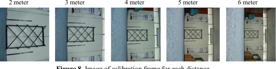
[image:4.595.71.542.612.730.2]Five observations were set at each object distances. There are six object distances to look for in this camera calibration. The views of the images from the camera at each object distance are shown in Figure 8.
2 meter 3 meter 4 meter 5 meter 6 meter
Figure 8. Image of calibration frame for each distance
Figure 8 shows the image size of the calibration frame decreased when the distance increased. The retro-target of 10 cm diameter still can be targeted in Australis software processing. It shows that two 8th International Symposium of the Digital Earth (ISDE8) IOP Publishing IOP Conf. Series: Earth and Environmental Science18(2014) 012039 doi:10.1088/1755-1315/18/1/012039
-0.01 0 0.01 0.02
2m 3m 4m 5m 6m
P
ar
am
et
er
's
va
lue
Object Distance
Parameter YP
set 1 set 2 set 3 set 4 set 5 3.00E-03 5.00E-03 7.00E-032m 3m 4m 5m 6m
P
ar
am
et
e
r's v
al
u
e
Object distance
Parameter K1
set 1 set 2 set 3 set 4 set 5 -2.00E-03 1.00E-17 2.00E-03 4.00E-032m 3m 4m 5m 6m
P
ar
am
et
er
's
va
lue
Object distance
Parameter K2
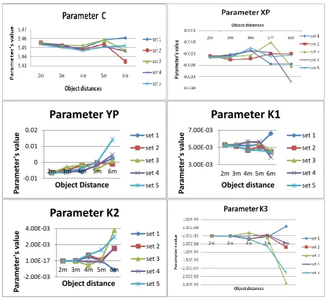
set 1 set 2 set 3 set 4 set 5 [image:5.595.66.540.117.549.2]until six meters object distance in doing calibration process it can be done. The result for each calibration parameter value in five set of observation are represented in Figure 9 below.
Figure 9. Trend of each parameter value from various object distances
Result in Figure 9 shows six camera parameters; focal length (C), principle distance (XP, YP), and radial lens distortion (K1, K2, K3). In two meter object distance, it shows that all camera parameters’ value marked close value at the graph line. In three meters object distance, camera parameter C, K1, K2, and K3 have quite similar and stable value within five set of observation through the graph. While, camera parameters’ value of XP and YP are uncertainties in small range.
All camera parameters in Figure 9 started to spread out the values when they reach up to four meters of object distance. In five and six meters of object distance, the values are unstable.
5. Conclusion and Future study
Through the result and analysis, the simple camera calibration cannot get stable parameter’s value when the distance is more than four meters (using 1.5 × 1 meter of portable calibration frame with 10 cm retro-target marker). The study shows that every camera calibration was affected by the object distance of the camera captured to calibration frame. Other error contributions need to be studied 8th International Symposium of the Digital Earth (ISDE8) IOP Publishing IOP Conf. Series: Earth and Environmental Science18(2014) 012039 doi:10.1088/1755-1315/18/1/012039
further, for example target distribution, angle of camera capture and light exposure.
Remondino, F.,
& Fraser, C. (2006). Digital camera calibration methods: considerations and comparisons.
International Archives of Photogrammetry, Remote Sensing and Spatial Information
Sciences
,
36
(5), 266-272.
References
[1] J Weng, P Cohen, and M. H 1992 IEEE Trans, Pattern Anal, Mach, Intell. 965-980
[2] Pan, M, and Zhu, G 2010International Conference on Optoelectronics and Image Processing [3] Remondino, F, and Fraser, C 2006
International Archives of Photogrammetry Remote
Sensing and Spatial Information Sciences. 266–272
[4] Hruska, R C, Lancaster, G D, Harbour, J L, and Cherry, S J 2005 Georeferenced Still Imagery [5] Grejner-Brzezinska, D A 1999 Navigation. 261-270
[6] Yang, Z J, Chen, F, Zhao, J, and Zhao, H W 2008 3rd IEEE Conference on Industrial Electronics and Applications. 2222–2227
[7] Fryer, J 1996 Whittles Publishing, UK 156-179
[8] Fraser, C S Springer Series in Information Sciences34 95-121. [9] Bösemann, W, Godding, R, and Riechmann, W 1990 SPIE. 119-126.
[10] Fraser, C S and Shortis, M 1995 Metric The Photogrammetric Record 107-122
[11] Jantos, R, Luhmann, T, Peipe, J, and Schneider, C Int. Archives of Photogrammetry, Remote Sensing and Spatial Information Sciences. 33
[12] Cronk, S, Fraser, CS. and Hanley, H. B. (2006). Automatic Calibration of Colour Digital Cameras. Photogammetric Record (in press).
[13] Kunii, Y. and Chikatsu, H 2001 Proceedings of SPIE Videometrics VII 278-287
[14] Läbe, T and Förstner, W 2004 Int. Archives ofPhotogrammetry, Remote Sensing and Spatial Information Sciences. 528-535
[15] Wiley, A G and Wong, K. W 1995 PE&RS. 69-74.
[16] Salvi, J, Armanguè, X and Batlle, J 2002 Pattern Recognition 1617-1635. [17] Niem, W 1999 Image Vis. Comput. 125–134
[18] Zhang, YJ, Zhang, Z X, and Zhang, J 2002 Geomatics Inform. Sci. Wuhan Univ. 566–571 [19] Zhang, YJ, Zhang, Z.X., and Zhang, J 2003 SPIE, Machine Vision Applications in Industrial
Inspection XI, SPIE. 291–296
[20] Maybank, S 1992 Int. J. Comput. Vision. 123–151
[21] Chiang, K W, Tsai, M L and Chu, C H 2012 Sensors (Basel, Switzerland) 9161–80
[22] Tahar, K N 2012 International Archives of the Photogrammetry, Remote Sensing and Spatial Information Sciences. ISPRS. 493–498
[23] Ariff, M F 2011 Phd Thesis, UTM, Malaysia.
[24] Atkinson, K B 1996 Whittles Publishing, Caithness, Scotland. 371
8th International Symposium of the Digital Earth (ISDE8) IOP Publishing IOP Conf. Series: Earth and Environmental Science18(2014) 012039 doi:10.1088/1755-1315/18/1/012039