University of Southern Queensland
Faculty of Health, Engineering and Sciences
Light Fidelity (Li-Fi) Prototype
with Raspberry Pi
A Dissertation submitted by
Paul Fergusson
In fulfilment of the requirements of
ENG4111 & ENG4112 Research Project
Towards the degree of
Bachelor of Engineering (Honours) (Electrical and Electronics)
i
ABSTRACT
With globalisation and the thirst for connectivity across society, the demand placed on wireless infrastructure and the associated resource is growing exponentially. Very soon this resource will reach saturation point, due to the finite bandwidth available in the Radio Frequency (RF) spectrum. A method of countering the impending saturation needs to be found. That method can be Visible Light Communication (VLC).
Light Fidelity (Li-Fi) is a research field within VLC that utilises the visible light band within the electromagnetic wave spectrum. This band is 10,000 times larger than the RF band and cannot be ‘leased’ or saturated with users. Light waves can be modulated to carry an enormous amount of simultaneous data, at speeds faster than current consumer equipment can handle.
This Dissertation describes in detail the research, construction and testing of a Li-Fi prototype using Raspberry Pi. The prototype is compact, low cost, uses accessible components and provides a solid foundation for other students to follow on with further work in this field.
ii
University of Southern Queensland
Faculty of Health, Engineering and Sciences
ENG4111 & ENG4112 Research Project
Limitations of Use
The Council of the University of Southern Queensland, its Faculty of Health, Engineering and
Sciences, and the staff of the University of Southern Queensland, do not accept any
responsibility for the truth, accuracy or completeness of the material contained within or
associated with this project preliminary report.
Persons using all or any part of this material do so at their own risk, and not at the risk of the
Council of the University of Southern Queensland, its Faculty of Health, Engineering and
Sciences, or the staff of the University of Southern Queensland.
iii
CERTIFICATION
I certify that the ideas, designs and experimental work, results, analyses and conclusions set out in this project preliminary report are entirely my own effort, except where otherwise indicated and acknowledged.
I further certify that the work is original and has not been previously submitted for assessment in any other course or institution, except where specifically stated.
Paul Fergusson
iv
ACKNOWLEDGEMENTS
I would like to thanks the people who have helped and supported me throughout my academic journey. Firstly I would like to thank my family for being patient, thoughtful, tolerant and supportive during times of stress and pressure. Without such an understanding and considerate family this process would not have been possible, nor would I have enjoyed the success I have reached.
Secondly I would like to thank the teaching staff of the University of Southern Queensland, without their dedication and devotion, the external student programs of the University of Southern Queensland would not be the successful institution they are today. Their commitment and sacrifice is a cornerstone to building professional and competent engineers.
Lastly I would like to thank my supervisor, A/Prof Alexander Kist. Without his insight, discipline and technical support I would not have decided to take on the challenges presented by this project.
v
TABLE OF CONTENTS
Abstract ... i
Certification ... iii
Acknowledgements ... iv
List of Figures ... viii
List of Tables ... ix
1 Introduction ... 1
1.1 Current Situation ... 1
1.2 Project Aim ... 2
1.3 Project Scope ... 2
1.4 Objectives & Expected Outcomes ... 2
1.5 Critical Analysis ... 3
1.6 Result Interpretation ... 3
2 Literature Review ... 4
2.1 Visible Light Communication ... 4
2.2 Raspberry Pi ... 5
2.3 Transmitter ... 7
2.4 Receiver ... 10
2.5 Signal Management ... 11
2.6 Signal Modulation ... 12
2.7 Encoding/Decoding ... 13
2.8 Existing Prototypes ... 13
2.9 Knowledge Gap ... 14
3 Project Methodology ... 15
3.1 Overview ... 15
3.2 Initialisation ... 15
3.3 Start-Up ... 15
3.4 Production ... 16
3.5 Execution ... 16
3.6 Project Closure ... 16
4 Prototype Development ... 17
4.1 Project System Diagram... 17
4.2 Transmission Module ... 18
4.2.1 Raspberry Pi ... 18
vi
4.2.3 Programming & Code ... 27
4.2.4 Cost ... 28
4.3 Receiver Module ... 29
4.3.1 Raspberry Pi ... 29
4.3.2 Photodiode Circuit ... 29
4.3.3 Programming and Code ... 33
4.3.4 Cost ... 34
4.4 Prototype System ... 35
5 Results Analysis ... 36
5.1 Analysis Approach ... 36
5.2 Tooling ... 37
5.3 Transmission Module ... 39
5.3.1 Transmission Circuit (PCB) ... 39
5.3.2 Power Supply ... 40
5.3.3 GPIO Protection ... 40
5.3.4 Lighting the LED ... 40
5.3.5 Addressable LED Testing ... 43
5.3.6 File Processing ... 46
5.3.7 Transmitting File Data ... 47
5.3.8 Data Modulation ... 48
5.3.9 Raspberry Pi & MobaXterm ... 50
5.4 Receiver Module ... 51
5.4.1 Receiver Circuit (PCB) ... 51
5.4.2 Photodiode & Amplifier Testing ... 52
5.4.3 Python Coding ... 54
5.5 Prototype Module Integration ... 55
5.5.1 Distance ... 55
5.5.2 Transmitting Square Waves ... 56
5.5.3 Transmitting File Data ... 56
6 Contributions, Conclusion & Future Work... 57
6.1 Summary of Contributions ... 57
6.1.1 Addressable LED’s ... 57
6.1.2 Raspberry Pi ... 57
6.1.3 Prototype Components ... 58
6.1.4 Construction ... 58
vii
6.1.6 Python and SPI ... 59
6.2 Review of Project Objectives ... 60
6.2.1 Objectives 1, 2 and 3 – Research ... 60
6.2.2 Objective 4 – Build a Prototype ... 60
6.2.3 Objective 5 – Transmit Video ... 60
6.2.4 Objective 6 – Quantity the Prototype ... 61
6.2.5 Objective 7 – Future Work ... 61
7 References ... 63
APPENDIX A – PROJECT SPECIFICATION ... 67
APPENDIX B – PYTHON CODE ... 68
B1. Transmitter Module Code ... 68
B2. Receiver Module Code ... 69
APPENDIX C – PROJECT MANAGEMENT ... 70
C1. Project Artefacts ... 70
C2. Risk Management & Standard ... 71
APPENDIX D – PRODUCT DATASHEETS ... 74
D1. Raspberry Pi 2B Layout Diagram ... 74
D2. Shiji LED APA102C (DotStar) Datasheet ... 75
D3. TI 74HCT125 Quad Level Shifter Datasheet ... 115
D4. Hamamatsu S5973 Photodiode Datasheet ... 116
viii
LIST OF FIGURES
Figure 1 - Radio Frequency vs. Visible Light Frequency Bands. Courtesy of author. ... 1
Figure 2 – Raspberry Pi 2B Microcontroller ... 5
Figure 3 – AdaFruit DotStar LED’s. Courtesy of author. ... 7
Figure 4 - Block Diagram of APA102C LED. Refer Datasheet. ... 8
Figure 5 - APA102C 32 Bit Signal Components. Refer Datasheet. ... 9
Figure 6 - Table VII from Kalavally et al. LED Based Indoor Visible Light Communications; State of the Art, IEEE 2015. ... 12
Figure 7 – Prototype System Diagram ... 17
Figure 8 - Raspberry Pi Zero. Courtesy Raspberry Pi Foundation. ... 19
Figure 9 - Raspberry Pi 2B Locations & GPIO. Courtesy RS Components. ... 20
Figure 10 - MobaXterm Start Menu Ribbon ... 21
Figure 11 - MobaXterm Session Option Window ... 22
Figure 12 - Raspberry Pi Configuration Menu. ... 23
Figure 13 - Raspberry Pi Terminal Check for SPI ... 23
Figure 14 - Raspberry Pi Terminal Check for SpiDev. ... 23
Figure 15 - LED Size Comparison. Courtesy Flexfire LED's. ... 24
Figure 16 - APA102C LED Mounted to Breakout PCB. ... 26
Figure 17 - Software Diagram for Transmission Module ... 27
Figure 18 - Hamamatsu S5973 Photodiode (TO-18). Refer Datasheet... 30
Figure 19 - Connection Circuit of OPA380 Transimpedance Amplifier ... 31
Figure 20 – Texas Instruments OPA380 TIA Graph to Select Rf Value ... 32
Figure 21 - GPIO Zener Protection Circuit. ... 33
Figure 22 - Software Diagram for Receiver Module. ... 33
Figure 23 - Image of Li-Fi Prototype ... 35
Figure 24 - Developmental Approach for System Integration & Prototype Analysis ... 36
Figure 25 - Fluke ScopeMeter 192C. ... 37
Figure 26 - Solder Paste applied to mount SOIC Components to DIP PCB's. ... 38
Figure 27 - TX Module Layout Diagram. ... 39
Figure 28 - GPIO LED Data Signal with SPI ... 42
Figure 29 - SPI SCLK GPIO Output Waveform Comparison ... 43
Figure 30 – Collimator used to increase LED directivity ... 44
Figure 31 - Multiple LED connection example (Shiji, 2014) ... 45
Figure 32 - Video screen capture of 1MHz modulation ... 47
Figure 33 - Example of Long Data Sequences... 48
Figure 34 - Differential Manchester Encoding ... 49
Figure 35 - Receiver Module Breadboard Layout ... 51
ix
LIST OF TABLES
Table 1 - Comparison of Present Market Micro-Controllers ... 6
Table 2 - Comparison of LED Alternatives for Transmission Module... 9
Table 3 - Costs Associated with Construction of the Transmitter Module ... 28
Table 4 - Comparison Table of Photodiode Terminal Capacitance. ... 30
Table 5 - Costs Associated with Construction of the Receiver Module ... 34
1
1
INTRODUCTION
1.1
Current Situation
We now live in a world that is infinitely connected through a multitude of invisible, networked pathways. They stretch and travel across houses, towns, countries and continents. We are a truly global society that now has an insatiable appetite for connection, information and convenience.
This intrinsic appetite has fuelled the proliferation of connection technology from crude military beginnings at DARPA (Dennis et al. 1988), through excruciatingly slow networks of public computers and onto networks increasing in speed and computational power, now without the use of cables. Almost exponentially the world has developed and embraced technology that now allows us to carry super-advanced, micro-computers in our pockets. The majority of these devices are connected wirelessly to internet service providers, who in turn connect to the World Wide Web. With a swipe of our finger we can find out the weather at that exact moment in Nairobi, St Petersburg and Honolulu. Aside from the developing detrimental effect this has on us socially, there is a price we are paying in the airwaves. This ‘wireless’ communication is carried out across the Radio Frequency (RF) band (ACMA, 2013) and limited by blocks of frequencies, each of a finite bandwidth. There will be a point in time when all of the available bands are all allocated, meaning the consumer blocks are clogged and causing ineffective and disrupted communication. Although a ‘First World Problem’ this will have a negative impact on society, with deeper exclusivity creeping into signal allocation and wireless communications.
A supplementary or superseding method of communication needs to be developed to combat the inevitable RF band saturation. There is such a method and it utilises a relatively untapped source of waves, with an extremely large bandwidth. This method uses the visible light spectrum band, which is shown (not to scale) in Figure 1 below.
2 It can be seen that the available electromagnetic spectrum of RF and Visible Light are disproportionately assigned in current communication methods. Not only is there larger space to grow into, it is ‘greener’, the band cannot be regulated, leased or saturated, it does not create electromagnetic interference with other devices and modulation of data can occur at frequencies that the human eye cannot detect (Stefan & Haas 2014). There is even research underway by Rajagpol et al. (2012) where data streaming is being conducted at light levels such that the light appears to be off according to the human eye. This could account for daytime or purposefully dark environments where people may use their devices.
With such a relatively new, green technology, the bounds are at the outer limits of current electrical equipment, much like Wi-Fi was when it was emerging. The applications appear endless, ranging from vehicle to vehicle communication, line of sight secure data networks, underwater communication (Rani et al. 2012) and all at communication speeds (>3GB/s) currently not accessible to everyday society (Stefan & Haas 2014).
1.2
Project Aim
The aim of this project was to produce a functioning, ‘proof of concept’ prototype that utilises VLC technology to send information to a related device across free space. The prototype should be low cost, compact and simple to implement.
1.3
Project Scope
The scope of the project was to research, develop, build and test a prototype system that would modulate Light Emitting Diodes (LED) such that the integrity and quality of information was preserved across free space and in turn received, then displayed on a suitable device.
A Raspberry Pi microcontroller could be incorporated to allow a compact, yet powerful tool to handle the system demands. This could help to put the prototype components within low budget reach of other students, consumers and researchers.
One of the foundations of the project was to enhance research in the area of Light Fidelity (Li-Fi) such that a wider, functioning architecture could be developed and implemented domestically, commercially or where the benefits of Li-Fi could be realised.
The scope of this project did not include;
Streaming audio and video signals,
Bi-directional Li-Fi communication between the devices, Integration with Wi-Fi and internet services,
Configuration of the video to interface with a mobile or portable device, Creation of an App to provide a User Interface, or
Multi-channel communication.
1.4
Objectives & Expected Outcomes
3 1. Undertake a literature review on visible light communication, modulation and signal
conditioning.
2. Undertake a basic requirements analysis
3. Critically evaluate alternative implementations and identify suitable components for the prototype implementation.
4. Build a basic prototype with physical components and achieve high speed square wave transmission.
5. Evaluate the performance and investigate improved modulation techniques for video transmission. Transmit basic video and improve to HD (720p).
6. Measure distance and video quality to define optimal prototype parameters. 7. Identify future research direction.
1.5
Critical Analysis
The prototype has a reasonably ‘black and white’ criteria for personal success. That is, if a file can be transmitted via modulation of LED’s across free space, then the prototype is largely a success. To focus the level of success into an academic sense, once a file is confirmed as sent and received, increasing the size of the file will be tested to determine the maximum level achievable with this set-up. This will be critical in determining the industrial usability of the prototype and also give other academics a base to work up from. Also changing to other file types should be considered.
Coupled with the size of the data signals that can be transmitted, the distance that the signal remains useable is also critical in any application consideration. Once the signal is working, I propose to increase the distance between the transmitter and receiver modules and testing signal size at each increment. This should result in a table of distance vs quality for the prototype, that can be objectively used assess performance.
1.6
Result Interpretation
To reach the conclusions for the project dissertation, a large step will be to get the prototype working. Should it not work, I will make recommendations throughout on how to progress from the work that I successfully complete.
If the prototype is working, the resultant distance vs quality table will determine suitable applications. For a public transport environment, lighting is typically situated 0.5m (from head) to 1m (from lap) above a seated person. This height aligns with the reach of a standard person to access fresh air vents, luggage racks, light switches and ‘call’ buttons. For centre aisles a similar distance can be assumed due to the raised ceiling at these points. For a domestic application, ceilings are typically 2.5m from ground level, therefore a seated person would have a ‘device height’ of up to 2m if sitting. The worst case distance would then be 2.5m if the device was on the floor.
4
2
LITERATURE REVIEW
2.1
Visible Light Communication
This literature review covers the published research relating to video or data transfer via VLC (Light Fidelity), in particular utilising Raspberry Pi or similar low-cost, consumer accessible microprocessor modules. It covers key project concepts such as any potential transmission and receiver circuit configurations, signal management, encoding and decoding of the data into a bit-stream and vice versa, and modulation techniques.
VLC is a field of research that has recently taken on greater importance within our lives. Take for example, the industrial pursuit for releasing to the public, society’s first truly operational ‘driverless vehicle’. The foundation of this technological product is built on the foundation of VLC (coupled with radar and machine vision). The concept of transmitting data via light waves is evolving into a subject that can yield solutions across our lives, including RF band congestion and quenching the global thirst for faster and more complex data transmission.
While Dr Harald Hass demonstrated video data transmission during his TEDGlobal talk Wireless Data from Every Light Bulb (2011), the technological complexities involved in that demonstration were out of reach of anyone other than PhD level academics.
Dr Haas is by far the leading worldwide exponent in the field and outside of his academic research at the University of Edinburgh, he has started his own company called pureLiFi (pureLiFi 2014). This company takes the scientific advances they test in the laboratory and turn them into consumer orientated modules. At present they have a 10Mbps half-duplex system (Li-Flame) that works at a distance of up to 3m (pureLiFi 2014). Although this system focuses on bi-directional internet access, any development of this platform is limited to commercial partnerships with the parent company or through PhD pathways at the university. The Li-Flame system also requires additional roof modules to be mounted next to the LED lights and preclude it from being integrated into many publicly accessible applications. This is largely due to the vandalism exponent and the ‘irregular’ intrusion into a ‘headspace’ envelope. For these reasons a recessed or concealed system is mandatory for commercial acceptance. Domestic applications may also gravitate to a more streamlined aesthetic such that there isn’t a multitude of ‘modules’ hanging down from the ceiling throughout the house.
Since the publication of Dr Haas’ research, there has been an exponential uptake in development of this technology and market research shows that within the next 7 years, the US market for VLC will grow to over USD$100b (Grand View Research, 2015). On the back of the increasing interest, and potentially fuelling this growth, there has been an influx of papers, journal articles and conference proceedings that simply regurgitate the buzz words and add little value to the knowledge base. Likewise, the majority of the undergraduate projects in this area are largely around simple transmitter/receiver set-ups connected to an oscilloscope as a ‘proof of concept’. If a simple search is run for “Li-Fi” on YouTube, it is plain to see under any of the Light Fidelity projects how many students are fishing for the project circuit diagrams.
5
2.2
Raspberry Pi
Whilst OMEGA achieved excellent data rates and parallel streaming, the package was not accessible to the consumer from a cost point or in a succinct package such as Raspberry Pi (RPi). Opening up the level of accessibility was attempted by Pathak et al. (2015) with a BeagleBone Black (BBB) module, but this research was limited to low data rate applications and not HD video transmission. Hunter, Conrad and Willis (2014) utilised a Raspberry Pi module coupled to a webcam in place of a photodiode receiver. Their execution of modulating a flashlight and using a webcam proved rudimentary but it did highlight via ‘proof of concept’ that Raspberry Pi modules have a place in these systems.
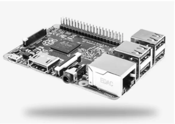
[image:15.595.152.445.407.615.2]In 2012, Uhan & Akbas discussed ‘HD video transfer to a projection device’ using Beaglebone boards and PandaBoard modules. Their method of transmission was wireless rather than using VLC, but they concluded that Raspberry Pi could be a future research area. The 2015 conference paper submitted by Nikhade on sensor networks again utilised Raspberry Pi but without VLC technology. Probably the closest work that has come to light is the 2015 BSc Thesis by Ambady, Bredes & Nquyen, which attempted to build on previous student research by transmitting audio using VLC and low-cost processor modules. They assessed a number of processors and decided to use an STM32 module over the Raspberry Pi. They encountered problems with the Analogue to Digital Converter’s (ADC) and although they managed audio signal transfer, it wasn’t HD video. Since that paper was submitted, Raspberry Pi have released two more powerful and updated modules (Raspberry Pi 2B and Raspberry Pi 3), which would have greatly assisted their project.
Figure 2 – Raspberry Pi 2B Microcontroller
6 possibilities of secure communication through the home lighting network. This is an area of future work for this prototype.
Klaver and Zuniga (2015) utilised Raspberry Pi and VLC in an effort to demonstrate multi-hop network viability using the technology. Their system was not wedded to a particular micro-computer but they did utilise the Serial Peripheral Interface (SPI) bus for receiving the modulated data as digital voltage levels. They also made use of Universal Asynchronous Receiver/Transmitter (UART) communications to permit bi-directional operation. UART is a possibility with Raspberry Pi and it has dedicated pins (BCM14 – TXD and BCM15 – RXD), but the grounds must be made common. A small tool called Minicom is used to assist with determining correct communication. This method would be useful for serial communication, and does need furthe consideration for Li-Fi applications.
Raspberry Pi does come with limitations and this has prevented other groups from utilising its emerging processing power. To start with, RPi is a 3.3V device and has current sourcing limits of 16mA per General Purpose Input Output (GPIO) pin with a maximum across all GPIO’s of 50mA. This is fine if the application has low current requirements, but it can expose the RPi to damage if more current is required. May hobbyists prefer the Arduino product due to being a 5V and able to source higher currents. There are a greater number of add-ons for Arduino as well, which many find more adaptable to RPi. The Raspberry Pi does win on processing power and is constantly evolving as a consumer product. It can capably handle media and can operate as a stand-alone computer. For this reason it is a suitable candidate for this application.
There are other comparable devices on the market, and a sample can be seen in Table 1 below. There is a wide and diverse range of options with varying positives and negatives for each. The two main producers are Arduino and Raspberry Pi. Arduino certainly have a significant following and array of prototyping options available, with their speciality in the robotics and interactive, small electronic projects area. They are widely stocked and supported with sensors, break-out and prototyping boards, lights, motors, actuators and anything that requires a small program to control.
The area where Raspberry Pi outperforms Arduino is the area of computing and micro-processing. The Raspberry Pi boards behave exactly as a miniture computer. They can connect to the internet, word process, operate with keyboards, TV’s, media processing and generally capable of any computng that doesn’t require significant processing or graphics. For this application they are ideal.
Brand CPU CPU
Speed
Memory GPIO Year RRP
(AUD) Arduino
Uno R3
ATmega 16U2
16MHz 32KB flash 14 pin 7-12V
2016 $43
Arduino M0 Pro
ARM Cortex M0
48MHz 256KB flash 48 pin 3.3V/6-15V
2015 $55
Raspberry Pi 3B
ARM Quad Cortex A53
1.2GHz 1GB RAM 40 pin 3.3V/5V
2016 $60
Raspberry Pi 2B
ARM Quad Cortex A7
900MHz 1GB RAM 40 pin 3.3V/5V
2015 $50
Raspberry Pi
Zero ARM11 Core 1GHz 512MB SDRAM 40 pin 3.3V/5V 2015 $35 BeagleBone
Black C
Sitara Cortex A8
1GHz 512MB
DRAM
46+46 3.3V
2014 $85
7
2.3
Transmitter
Aside from media handling and modulation, a fundamentally important aspect of Light Fidelity is the performance of the Light Emitting Diode (LED) transmitter and photodiode receiver themselves. Regardless of whether the system is being used to transmit data packets for bi-directional internet access or packets of modulated video signal, the LED’s need to be capable of switching on and off at the required rates. Hetian et al. (2015) prescribe an LED modulation rate of at least 2-3MHz to ensure that it is above the perceptible rate of the human eye, but this is not at a suitable level to transmit large volumes of high quality data. Grobe et al. (2013) touch on the subject of using laser diodes to achieve speeds greater than 3Gb/s. Although fantastic for a laboratory, these are approximately $80 each (0.8mW blue) let alone spending more money on a suitable receiver. These would not be practical for a domestic or commercial lighting application.
Research from 2011 by Langer et al. utilised white (RGB) phosphorescent LED’s (at up to 54MHz) with ‘a low cost Positive Intrinsic Negative (PIN) photodiode’, and confirmed transmission speed of 230Mb/s. Chang et al. (2015) produced a paper specifically on LED suitability for VLC with blue and green specific LED’s giving the highest ‘bandwidth of 225 and 463MHz respectively’. However, for a domestic or commercial lighting application white needs to be the visible colour. Probably the most comprehensive research published in 2015 for the subject of LED’s and VLC was by Kalavally et al. They run through each marketable LED type and describe the properties in reasonable detail. A key fact to come out of their paper is that ‘a study on the type of LED suitable for VLC (is) yet to be done’. This presents that while there are many options, one defined or perfect solution is not yet published.
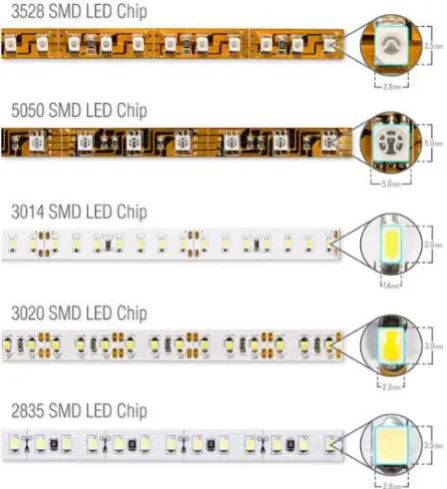
One aspect of LED development that has emerged in recent years is the micro, addressable LED. These are typically 3-4 separate elements, each of a similar material that has the colour output determined by a varied digital signal sent to it. Many of these are coming in LED strips in 10’s of meters long. They can be provided with a single clock signal and the data is passed from one LED to the next. Each LED can be separately addressed and provided with a colour signal, with typically low voltage and current requirements. Longer chains can experience degradation of signal logic, but they can be split with multiple, synched controllers. What makes these attractive to consumers is the ease of use and the multitude of lightweight and impressive applications.
Many LED’s in this format are denoted by the size of the luminous element. These include the WS2812 which has a 5050 element and integrated controller chip and also the 3528 LED. The numbers represent the dimension of the LED, such as 3.5mm x 2.8mm for the 3528. The 3528 is commonly surface mounted to a strip at a rate of 60 per meter and have a low power demand ~5W at 12V. The 5050 LED strips are again typically at a rate of 60 per meter but have a higher demand (~15W at 24V) and a much higher lumens output.
8 While these strip lights had an increasingly popular application in domestic and commercial environments such as hotel lobbies, aircraft lighting, home feature walls, exterior signage etc, they have not been widely considered as a communication device. A knowledge gap existed between the integration of an addressable and scalable LED strip as a feature or functional light source and as well as a VLC medium. Whilst a singular prototype could be used to prove the concept, the power supply could be adapted to power many strips and could possibly emerge to the market as a modular system. The majority of the LED strip lights are powered by 5V, but have been tested to work (although not reliably) at 3.3V, they lean towards Arduino applications. In fact, the majority of publicised examples are of this combination rather than Raspberry Pi. AdaFruit Learning Systems have provided a NeoPixel Uber guide (Burgess, 2016) on their website to cover all sorts of applications and this includes tailoring the 5V LED’s to a 3.3V microcontroller (RPi). The 3.3V signal is sent from a Raspberry Pi and passed through a 74AHCT125 Logic Level Shifter. This chip converts the lower voltage signal into the 5V signal necessary for the LED to recognise the logic level. This does complicate the circuit a little, but the benefits of media handling and PC-like operation make the effort worth it.
The Logic Shifter also is required to be used with ‘buffer’ resistors on the GPIO’s to prevent inadvertent action of turning an output into an input, potentially causing damage to the Raspberry Pi. These are simple 330Ω resistors placed in line with each GPIO (SCLK and MOSI in this instance).
AdaFruit have released an improved version of the 5050 LED that makes them attractive when requiring a persistence of vision application (non-flicker) or for high speed display purposes. Each APA102C LED (DotStar) is integrated with a chip that includes a shift register, decoder, PWM generator and these facilitate very high clock speeds (up to 32MHz). There are 6 pins on the APA102C; DATA IN, DATA OUT, CLOCK IN, CLOCK OUT, GND and POWER (5V). They usually come in strips, but can be used individually. They really show their worth when connected in strips as they do not require a set PWM signal (unlike the WS2812 which is strictly 400Hz) and can operate up to 20MHz PWM.
Figure 4 - Block Diagram of APA102C LED. Refer Datasheet.
9 Figure 5 - APA102C 32 Bit Signal Components. Refer Datasheet.
The LED’s require a start frame of 32 ‘0’ bits. One of the APA102C benefits comes when after each data signal is received by an LED, it will send a 32 bit string of ‘0’, essentially telling the next LED to be ready for a change. This string is passed down the strip so that each LED is active and waiting. The LED’s are addressable so you can instruct individual LED’s to light any colour, turn on or off and at any brightness. This presents an advantage for moving pictures, feature lighting or large matrix displays. The two wire Serial Protocol Interface (SPI) allow for separate clock and data in signals, which is another benefit above the single wire WS2812. This advantage removes the need for critical timing sensitive operations with the WS2812.
Because the LED can demand current right near the recommended values for the GPIO, a separate 5V power supply would typically be required. The RPi 5V output is actually a shared voltage with the demands of the processor and can be unreliable if you’re running a number of applications at the same time. Because this is likely with playing or streaming video’s plus encoding applications or code, a separate supply will take away that potential for issues.
Additional considerations are the optical wavelength output of the LED’s, beam dispersion, the rate that they can be modulated at and the output power. You want to match the wavelength with that of the receiver photodiode to ensure that the signal is correctly received. Understanding that wavelength can also allow you to narrow your photodiode specification to reduce effects of ambient light.
If the output power of the LED’s are low, the received signal may not be able to be distinguished from ambient light. If the output power is too high, you will need to factor in heat management and the application may be too harsh for interior domestic lighting! Dependent on the number of LED’s, beam focussing via optical lens may be required. This would narrow down the use of the prototype so would be an option of the design needed it.
Model Luminous
Flux
Addressable Type Voltage/
Current
Frequency Cost
Cree XML XLamp
260 Lm No W 3.1V unknown $7.60 ea.
APA102 DotStar
18 Lm Yes RGB
WWW
5V/120mA 20kHz PWM
$4.5 (10LEDs) WS2812
NeoPixel
18 Lm Yes RGB 5V/60mA 400Hz
PWM
$25 (60LEDs)
SK6812 7 Lm Yes RGB 5V/60mA 1.1kHz $25
(60LEDs) Kingbright
NSPW500
20 mcd No W 3.2V unknown $1.50 ea.
Lumileds LXML
180 Lm No W 3V unknown $4.25 ea.
10
2.4
Receiver
From an optical receiver perspective, there are typically two generic choices for the sensor; an Avalanche Photodiode or a PIN Photodiode. Kalavally et al. (2015) describe that the Avalanche has the better gain, but at a cost of shot noise in the photocurrent. PIN Photodiodes are better in high temperature, high saturation environments and are the general preference in VLC. Chung et al. (2015) proposed a filtered photodiode cluster arrangement to produce 3 separate channels (RGB) for a bi-directional system. While this may have a use for larger applications, unless bandwidth becomes a limiting factor, the complexity will preclude it from being explored further here.
The receiver is probably the most complex aspect of the system and the most critical to get right. With transmitted light, the received levels are very small and susceptible to noise, capacitance and amplifier circuit oscillation. Considerations need to be given to a low capacitance photodiode, one that can handle faster speeds, one that has a good bandwidth product (for signal gain) and one that has a level of simplified use. Cost was a minor consideration as well as accessibility to students or consumers. For this reason, consumer electronic retail outlets such as Element14 and RS Components were contemplated for provision of suitable devices. Many of the scientific papers were laboratory based and used expensive (>$300) modules in their test beds and set-ups (Kamsula 2015). Here, the execution is required to be ubiquitous, accessible and compact. As such, the Hamamatsu Photonics S5973 series photodiode appeared as a suitable candidate.
Photodiodes can typically be connected in two different configurations; photovoltaic or photoconductive modes. Photovoltaic mode is where the diode is unbiased (without reference voltage) and the voltage produced is non-linear when compared to the amount of light on the sensor window. This method can be likened to the operation of solar cells when light produces a voltage but it also reduces the dynamic range of the diode. Photovoltaic mode is preferred when sensitive measurements are required, as there is a smaller signal offset and less noise induced in that area of the circuit and passed to the amplifier stage.
Photoconductive mode is where a reverse bias voltage is applied and results in lower capacitance, thus higher switching speeds at the detriment of producing additional heat. Other drawbacks of this mode are that the configuration is noisier and has a higher dark current over photovoltaic mode. The produced photocurrent is however linear over a certain range. Photoconductive circuits are more suited to high light ‘power’ and high speed applications.
Given that the Raspberry Pi power GPIO’s are either +3.3V or +5V (no negative swing), this will largely dictate the photodiode set-up and component selection. That is, a low power, low current diode that can operate suitably in photovoltaic mode. The amplifier stage will also need to perform within these bounds, in particular with a single supply.
11 In Orozco’s 2014 Technical Article about optimizing precision photodiode circuit design, he outlines that when selecting an amplifier, the order of important considerations are input offset voltage (to be as low as practical), input leakage current (again as low as practical), circuit layout (to minimise external leakage) and noise management. He goes into reasonable detail on how to compromise and reduce many of the common problems with this type of receiver.
Some designs have required a second stage amplifier which are AC coupled to block any unwanted DC voltages sent from the first amplifier stage (Kitchin, 2007).
A key limitation for this application is the low voltage supply level (3.3-5V) from the Raspberry Pi GPIO. One of the design aims is to make the prototype as ‘modular’ and self-contained as practical. Introducing additional separate power supplies move away from that concept.
A final consideration is to provide a protection circuit on the output of the receiver circuit that feeds to the Raspberry Pi GPIO. This will prevent damage to the microcomputer and is a small investment for the design. These can range from opto-isolators, transistor switches and Zener diodes (eLinux.org). The Zener circuit is simple to implement for RPi, with a 330Ω resistor and 3.3V Zener diode between the GPIO input pin and the output of the receiver circuit.
2.5
Signal Management
The ultimate goal of the transmitter and receiver system is to send a digital signal that represents a more complicated signal (video) and preserve the original content. For this to happen, the content must first have the binary data extracted, then transmitted with accuracy, received clearly and amplified to represent the same format as the transmitter was given.
Probably the main contributor for digital signal degradation is noise. Noise is the unwanted signals that interfere with the useful information you’re transmitting/receiving/measuring. It can come in many forms such as thermal noise, shot noise, jitter and electromagnetic interference. Prototyping and small signal measurement circuits are susceptible to noise as often the environment (breadboards, multiple wires etc.) is highly capacitive and can easily swamp any small signals you’re trying to utilise.
The Transimpedance Amplifier Application Report written by Xavier Ramus (2009) talks about compromises between gain and Johnson noise caused by the feedback resistor. If you choose a large value resistor, you will have plenty of gain, but introduce more noise to be amplified. Many of the other reports created in this field talk about using capacitors to short between power supplies and ground (Texas Instruments, 2007 & Orozco, 2014). Photodiode leads should be a short as possible and as close to the TIA as practical and breadboards are fine for circuit function, but should be transferred to PCB’s for final execution.
At speeds above 10kbps Klaver and Zuniga (2015) experienced deformation of the generated square waves and this made the demodulation process complicated. They had to settle for a 1kbps limitation in transmission rate to guarantee that the quality of signal was preserved. The cause of the deformation was not discussed nor mitigated in their paper.
12
2.6
Signal Modulation
The modulation of the light is a broadly debated topic. Kalavally et al. (2015) cover in detail over ten different methods, as well as a multitude of dimming techniques. Again, no defined modulation preference is presented and with reference to Table VII of their 2015 paper (pictured over), the closest preferred method is On-Off Keying (OOK) or a derivative (e.g. NRZ-OOK). Langer et al (2011) said for ‘data rates up to 100Mb/s, standard OOK is sufficient. To get higher, you need to use Dual Multi Tone (DMT) modulation techniques and you can get up to 800Mb/s’. OOK modulation will be considered for the first tests but the data rates, complexity and circuit performance may necessitate utilising alternative schemes.
If an addressable LED is used in the transmitter, consideration will be given to the size of data packet that needs to be sent to the LED. Additionally, the LED’s are typically capable of variable brightness (through PWM) so this will add another dimension of data encoding to the digital signal. This however, may complicate the receiver circuit with regards to rising/falling edge detection and level detection across 0-3.3V.
13
2.7
Encoding/Decoding
A common video format in use today is MPEG-4 (h.264). This format is used in Blu-ray discs, mobile devices, High Definition (HD) video storage and digital HD television (Marpe, 2006). It is favoured because of its ability to be greatly compressed without significant loss of quality. This fact would make it suitable for Li-Fi applications to reduce the amount of information processed, transmitted and received. That said, the management of codecs may prove to be outside the level of the project. Caihong et al. (2013) introduce the benefits of a powerful open-source multimedia framework called FFMPEG as one that can handle various transmission protocols, media container formats and regular video codecs. They state that it has suitable algorithms for real-time media processing. This did not use Raspberry Pi for their solution, but the paper content does give hope it can play a part in managing codecs and video.
A number of papers exist where the authors have utilised Field Programmable Gate Array (FPGA) boards to manage the encoding and data transfer from parallel to serial bitstream (Zhu et al. 2015, Wang & Xu, 2015). An FPGA can also be used as a buffer to store frame data from the video file for processing. This can be applied to the transmitter and receiver modules. A buffer could be used on both sides of the system, with the use of pointers and read commands to create and collect the appropriate data in sequence.
Wang and Xu (2015) specify Manchester coding for long distance communication to compensate for a lack of synchronisation information and to provide a level of immunity to interference. They go further to use 4B/5B encoding that uses 5 bits to send each 4 bits of data from a predetermined dictionary. The downside is that more bits are required for the same information but the upside is that 4 bits without transitions (e.g. 0000, 1111) is sent with a corresponding 5 bits from the dictionary, with transitions introduced (e.g. 11110, 11101 respectively). This approach is also included in Jia et al. VLC/FPGA prototype. Additionally, they favour Manchester coding to lift the LED average power and thus eliminate any perceived light flicker.
2.8
Existing Prototypes
Utilisation of a Raspberry Pi microcontroller to stream video already exists and a low latency example using Wi-Fi was discussed by Petr Kout (2014). He employed an existing application called MJPG Streamer that used the 8080 port of the Raspberry Pi to transmit the video data via wireless channels. The application handled all of the video and audio mux conversion as well as the encode/decode process. While this is simplistic and market ready, it does not address the issue of Radio Frequency saturation, nor is it suitable for modulation of LED’s. Perhaps the front end interface of MJPG Streamer can be tailored to modulate an LED to send the data packets.
14
2.9
Knowledge Gap
VLC is still young in its technological cycle, but with the groundswell of interest in this topic, it won’t be long before it starts to make its way into mainstream environments and homes.
Whilst a handful of undergraduates are showing interest in this technology, they appear to be starting from scratch each time and would greatly benefit from a solid baseline to start from. Designing such a prototype and publishing the configuration and performance figures would greatly enhance the uptake for future development.
From the above literature review conducted on the topic, it is clear that there is a knowledge gap in the area of a low-cost, consumer accessible platform using Light Fidelity (and VLC) technology and addressable LED’s to transmit high definition video signals. Indeed, the lack of collated information around Raspberry Pi video transmission, bit-stream creation and file management warrants the contribution of this research project.
15
3
PROJECT METHODOLOGY
3.1
Overview
This project was purely one of research and experimental work. The project was executed as a progressive development of concept following a body of research and expansion of ideas to achieve the aim. The steps generally followed a typical Project lifecycle model from the Project Management Book of Knowledge (Stackpole, 2010).
Project Initialisation – research proposal, literature review, design information Project Start Up – procurement, production readiness
Project Production Phase – build the prototype
Project Execution – get the prototype working, test and develop Project Closure – write up dissertation, demobilisation
3.2
Initialisation
The Project Initialisation Phase was a combination of producing a preliminary report, deeper research into prototype specifics and formalisation of the project scope and outcomes.
This phase was purely research driven and the investigation carried out defined the general shape of the project. Significant information was gathered during this phase and a thorough search helped to prevent errors or miscalculations during construction.
The outputs of the Initialisation Phase were;
A mental roadmap of the Project direction, with alternative routes in reserve, A list of required resources, and
Set-up of a Project Diary to track daily progress and the reasons behind the various decisions made throughout the Project.
3.3
Start-Up
The Project Start-Up phase took the outputs from the Initialisation Phase and built on them to begin the procurement of Project resources, allocation of Project space, Project management systems and to mark the start of the physical work phase of the Project.
This phase moved the Project from an idea, theory and research based Project to one that was tangible. Outputs of the Start-Up Phase were;
An allocated workspace to construct the prototype, Focussed research to a preliminary modulation technique,
Understood how to drive the LED’s from a 3.3V Raspberry Pi output signal to a LED i/p signal All necessary software downloaded and installed, and
16
3.4
Production
The Production Phase marked the start of the actual building of the prototype. This was undoubtedly one of the most exciting aspects of the project and brought with it the start of the major challenge to get it working.
The outputs of the Production Phase were;
Build and develop the LED driver circuit to deliver the required voltage to modulate the LED’s, and
To completely construct all power supplies, equipment and components.
3.5
Execution
This phase contained the largest amount of work, frustration, technical demand, support and investigation. The primary focus was to get it working and then to look for optimisation and improvement, time permitting.
The planned sequence of work was;
1. Connected power supply and signal management circuits to drive LED’s on,
2. Confirmed that photodiodes could receive the LED’s being manually switched on and off, 3. Used the Raspberry Pi (RPi) transmission module (TX) to create a simple square wave to send
to the RPi receiver module (RX) and achieve basic communication, displayed on a screen or other output device,
4. Increased data speed (via small steps) and maintained expected outputs,
5. Attempted to send a file across free space, maintaining the quality of the original. The outputs of the Execution Phase were;
A Project Diary that recorded the path followed throughout the Project to provide a resource to build the Dissertation from,
A working Prototype that could send files across free space using Visible Light Communication technology, and
A final configuration (including software + code used) of the system.
3.6
Project Closure
The Closure Phase intends to wrap up the Project and finalise all aspects ready for academic submission. Closure includes decommissioning the prototype system, returning borrowed or loaned equipment and writing up the results. Should the Project provide suitable material, a publishable paper could be written to give information to the wider engineering community.
The outputs of the Project Closure phase are;
An academic Dissertation submitted to USQ for ENG4112, Decommissioning of the prototype, and
17
4
PROTOTYPE DEVELOPMENT
This chapter describes in detail the steps that were taken to arrive at a working prototype. It covers all of the technical information, principles and operation pertaining to the prototype.
4.1
Project System Diagram
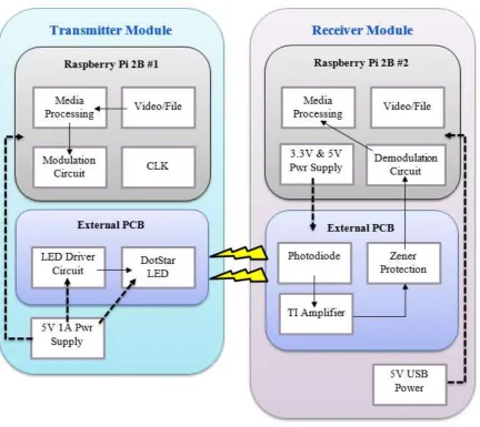
The system can be broken down into two sub-systems; the Transmitter (TX) and the Receiver (RX). Each one is made up of smaller functions such as the LED electrical control circuit and board, the photodiode electrical control and board, the software in the TX and RX modules, the peripherals (keyboard, monitor, mouse etc.) and support software (e.g. MobaXterm).
[image:27.595.84.517.295.680.2]The Figure below illustrates how the prototype is made up from a system point of view and shows the interaction between the varying components.
Figure 7 – Prototype System Diagram
18
4.2
Transmission Module
The transmission module has the function of selecting the file to transmit, extracting the binary data from it, coding that to serial data on a GPIO, processing that data through a level shifter and turning ON/OFF an LED accordingly.
4.2.1
Raspberry Pi
4.2.1.1 Why Raspberry Pi?
The Raspberry Pi was selected as the micro-controller over the Arduino family of devices due to its ability to handle faster processes, its versatility across all aspects of computing, low cost and simple to use package. The Arduino family does tick off the low cost and actually has a wider range of supporting devices such as sensors, displays, lights, data processors, but it was assessed for this project as not suitable for the potential media handling and general computing requirements of the project. Arduino’s are very popular with robotics and hobby projects, more targeted to smaller engineering-type projects. Raspberry Pi offered the diversity to prevent the project arriving at a roadblock that was unable to be overcome, such as processing speed or data management. The RPi 2B CPU has a clock speed of 900MHz and can be overclocked to 1000MHz whereas the Arduino’s (in the same price bracket) have CPU speed <100MHz. Additionally, the RPI came as a complete package, with Arduino requiring ‘bolt-on’ components which would have increased the cost and complexity.
Other micro-computers were considered, but the support documentation, availability, cost and function removed them from final selection and purchase. A table of these has been presented earlier in this document.
4.2.1.2 The Raspberry Pi Family
Raspberry Pi is compact, single board and relatively powerful microcontroller that was developed by the Raspberry Pi Foundation in 2012. The first board was named Raspberry Pi A version 1. It consisted of ‘256MB of RAM, one USB port and no Ethernet port’ (Raspberry Pi Foundation 2015). The CPU was a 700MHz single core ARMv6 (32 bit) processor and is still regularly used for embedded projects or those that have simple requirements such as media management behind TV’s.
From these simple and successful beginnings, a B model was released followed by A+ and B+ upgrades a year later. These retained the same processor and CPU, but had an increase in RAM to 512MB. While the size of the boards stayed the same, more ports, GPIO pins and peripheral connectors were added to increase project flexibility. These included HDMI 1.3, Camera slot, 3.5mm audio jack, Ethernet and a microUSB for power application.
It wasn’t until the release of Raspberry Pi 2B that board performance really took a step forward from the early models. This was released in February 2015 and came with a 900MHz 32 bit Quad Core ARM Cortex A7 CPU and 1GB of RAM (Raspberry Pi Foundation 2015). USB ports were increase from 2 to 4 and the inclusion of a MicroSDHC slot to save space on the board. The release of RPi 2B coincided with a growth of hobbyists, students and teachers utilising RPi for learning and projects alike. Their versatility and relative low cost compared to performance meant more and more people could access the technology. At the time of commencing this project, the RPi 2B was the latest model.
19 it still came with a 1GHz ARM11 single core CPU and 512MB of shared RAM. There was room for a USB and HDMI port with mini camera interfaces and a 40 pin GPIO.
Figure 8 - Raspberry Pi Zero. Courtesy Raspberry Pi Foundation.
With the Pi Zero shipping after the purchase of the RPi 2B’s and the limited supply run, this hindered any potential use in the project. Regarding future work, it would be perfect to be the processor for any Internet of Things (IoT) projects due to the small size and reasonable performance. A wireless dongle can be connected to the USB port and easily configured to allow internet access for this mini-computer. Once on a network, a remote access application such as MobaXterm can be employed to control every aspect of the device if it was embedded or attached to another appliance.
In February 2016 the Foundation released another significant member of the family with the RPi 3B. The upgrades included a 64 bit ARMv8 (Cortex A53) Quad Core processor running at 1.2GHz. Wireless Ethernet (802.11n) and Bluetooth 4.1 were noteworthy additions to the board (Raspberry Pi Foundation 2015) above the specification of the RPi 2B. This does come at a slight cost in that you will need 2.5A to power these new performance features, which is up from 2A with the RPi 2B (RS Components 2015).
4.2.1.3 Software
Raspberry Pi functions with a Linux based distribution as its operating system (OS). The particular OS they provide for download (Raspberry Pi Foundation 2015) is Raspbian. This is a Debian based Linux version that uses the Linux Kernel and other applications, which are generated as Open Source software by a large group of contributing programmers (SearchEnterpriseLinux 2016).
20
4.2.1.4 Configuration
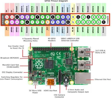
[image:30.595.110.497.225.567.2]The 40 pin GPIO is what makes the RPi 2B so versatile in what it can be used for. Among the pin configuration there is +3.3V and +5V power supplies, but they actually share the supply current with the rest of the CPU. In fact, the RPi 2B is limited to a 2A input which is protected by a polyfuse (F1), and the 4x USB’s are allowed 1.2A max. This then leaves 800mA (if everything is being driven hard) so if the CPU, USB’s or other GPIO’s are sinking a lot of current, the output voltage pins are not able to supply much at all. Conversely, if the USB devices use 1A, then there is 1A for the CPU, GPIO’s and outputs.
Figure 9 - Raspberry Pi 2B Locations & GPIO. Courtesy RS Components.
The GPIO’s themselves have current sink/source limits and care must be taken when planning to connect external devices. Individual pins must not pull more than 16mA and the entire GPIO must not source more than 50mA (Clifford, 2016). Therefore the RPi is only suitable for connecting low power demand components to rather that current hungry devices.
21
4.2.1.5 Peripherals
To use the RPi as a micro-computer you will need some way to interface with the CPU. This typically comes in the form of a keyboard and mouse, with the output of your commands being displayed on a monitor. On the RPi 2B there are 4 USB ports to plug in such devices and an HDMI port for your monitor. There is a DSI Display Connector to plug in a TFT or LED display. A webcam can also be plugged into the CSI Camera Connector as well. The location of these on the board can be seen in the Figure above.
A key item to include when setting up is a wireless dongle, although if you wanted to you could connect a standard Ethernet cable to the available port. The wireless dongle is simply connected to one of the USB ports and this will allow you to connect to the internet as well as keep your Raspberry Pi updated with the latest software releases. Additionally, if you know the IP address you can connect to the RPi remotely using a multitude of applications. The Raspberry Pi Foundation website has a list of these methods under >>help>>documentation>>remote access. These include Weaved, VNC, SSH and Web Server.
4.2.1.6 MobaXterm
For this project a freeware program called MobaXterm was used. This allowed access to the RPi using an existing computer, keyboard, monitor and mouse, so that additional peripherals weren’t required to operate the RPi. All that was required was a wireless dongle, the IP address of the RPi and a download of the MobaXterm application (Mobatek, 2015).
Connecting the RPi is simple. Power up the device then open the MobaXterm application. Select >>Session from the menu shown in the Figure below;
Figure 10 - MobaXterm Start Menu Ribbon
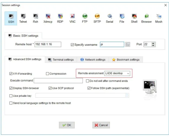
From there another window will pop up and select >>SSH, then enter the >>Remote Host IP address (your RPi), select >>Specify Username (your RPi name) and finally select >>Remote Environment as >>LXDE Desktop. Select OK.
A separate window will open that will show the RPi desktop on your PC’s monitor. You will be required to enter your RPi password on the session window. Once this is all complete, you will be able to control your RPi from your existing peripherals.
A limitation of this set-up is that you cannot copy and paste or drag from the RPi window to your PC. Any information transfer needs to be done via the File Transfer Protocol (FTP) option on the left hand side of the session window. Here you can upload files from your PC to folders on the RPi and vice versa.
22 Figure 11 - MobaXterm Session Option Window
4.2.1.7 Setting up RPi
Once you have your RPi and the operating system of choice, it is as simple as following the installation guide on the Raspberry Pi Foundation’s website. After you have the peripherals and/or remote access established, you should open the Terminal application (also known as Command Line) and start an update and upgrade of applications. This keeps your programs running with the latest features and bug fixes.
In the command line enter >>sudo apt-get update and follow the prompts. Next enter >>sudo apt-get dist-upgrade and follow the prompts.
If you are running out of space on your RPi, you can get some back by removing the unpackaged files that you download as part of these updates and upgrades. Again, go to the command line and enter>>sudo apt-get clean.
4.2.1.8 SPI
The Raspberry Pi presents a reasonable amount of transmission methods and protocols for the movement of data. The two most common and well supported are Serial Protocol Interface (SPI) and Universal Asynchronous Receiver/Transmitter (UART). Both transmission functions were suitable for the method to send the data through the GPIO to the LED circuit but SPI was better supported with literature and internet information. SPI uses GPIO pins 19+38 (MOSI), 21+35 (MISO), 23+40 (SCLK), 24 (CE0) and 26 (CE1), so you it can be utilised for two separate sources.
23 Figure 12 - Raspberry Pi Configuration Menu.
A reboot is required for the change to take effect. Once it has been enabled, you can check that it is working by first typing >>lsmod in the Terminal application and you should see “spi_bcm2835” in the list.
Figure 13 - Raspberry Pi Terminal Check for SPI
To actually use SPI, you need to have a Python library installed to act as the ‘SPI wrapper’. This library is now included in the latest Raspbian image, but it pays to check that it is present. Type >>apt-mark showauto | grep spi in Terminal and you should see the two spidev libraries as per below;
24 The SPI clock (SCLK) can have the speed changed in powers of 2, from 500Hz up to 32MHz. Worth noting is that if you don’t set it to one of the powers, it will default down to the nearest power of 2 value. For example, setting the SCLK to 21MHz will produce a clock speed of 16MHz.
4.2.1.9 FFMPEG
FFMpeg is freeware that works with Linux to encode and decode audio and video files. It’s used inside various popular video platforms to convert, play or stream video and audio. This package was reviewed as a candidate to handle the media conversion before the transmission circuit. After a detailed review of the complexity involved with video and audio streaming, the use of FFmpeg was discounted.
4.2.2
LED Circuit
The LED circuit is the centrepiece of the project and directed the function and performance required from the other aspects of the prototype. The desire to utilise addressable LED’s in an effort to explore data transmission from modern lighting set-up’s (public transport, feature lighting etc.) eliminated standard singular LED’s.
Reflecting on this decision, the use of a singular, bright LED would have been a simpler aspect to integrate into the prototype and possibly would have allowed deeper progression towards the aim and objectives.
This circuit also consisted of a method to shift the Raspberry Pi’s +3.3V GPIO to the LED’s required +5V, protection and mounting of a beam focusing device for the LED.
4.2.2.1 Addressable LED’s
[image:34.595.188.412.488.733.2]Putting aside the singular LED style, the addressable LED market is limited to a small number of standard packages that are then tailored by manufacturers. Typically, these packages are dictated by the actual size of the lighting element. Common annotations are 5050, 2812 and 3528, with the chart below showing examples of Surface Mount Device (SMD) LED’s on strips.
25 Addressable LED’s are able to be individually controlled by sending a series of bits to the on-board shift registers that contains information such as brightness and what segment to light up (RGB) to get the desired colour or hue. The information is clocked through and can either be changed each clock or left the same and selected to change later on. The advantage of this is that you can get a large amount of control and displays to happen with simple coding and libraries.
The approach that was undertaken with this project was to control a single LED at first and to determine whether it was a viable option to continue onto the strip lighting. This has the effect of keeping cost to a lower level (individual LED’s as opposed to a whole strip purchase) and also the result at first would not have to consider parallel signal paths through multiple LED’s. This is something that would need to be considered for future work.
4.2.2.2 DotStar vs NeoPixel
The two main addressable LED’s on the market are produced by AdaFruit Industries, which is a company that was set up in 2005 to capture an increasing niche market in hobby electronics (AdaFruit, 2016). They manufacture and supply microcontrollers (Raspberry Pi, Arduino, Beaglebone) and supporting components such as cables, chips, break-out boards, electroluminescent panels, development boards and LED’s.
Their two most popular LED’s are branded NeoPixel and DotStar. The NeoPixel’s are effectively 5050 RGB LED’s with an integrated driver chip inside a WS2811 LED. They have a strict timing requirement and are better suited to a ‘real-time microcontroller or interpreted microcontroller’ (AdaFruit, 2016), such as the Arduino, but not the RPi. This fact, coupled with the preference to use the Raspberry Pi, eliminated the slightly older and slower NeoPixel LED from being used on the project.
This left the newer DotStar branded APA102C smart LED as the preferred addressable option. They are sold as a strip and in single form (10 pack) from the AdaFruit website (AdaFruit Industries, 2016). They come in two colour temperatures (cool or warm) and in RGBW or WWWW element configuration. The WWWW option was selected to provide a more consistent and pure output compared to blending the 3 RGB elements to get white light out. The APA102C LED’s have integrated shift registers and PWM encoders (iPixel LED, 2014) embedded into the LED that enable the user to set the brightness once and it is provided to the strip or singular LED until you change it.
26 AdaFruit have an extensive support page for NeoPixel’s and DotStar’s with Phillip Burgess’ (2016) popular Uber Guide providing an industry bible of sorts for hobbyists starting out on addressable LED projects. The Uber Guide covers mainly NeoPixel’s but the principles can be applied to the DotStar as well. It includes detailed topics of power supplies, Arduino and Raspberry Pi Libraries, form factors, connections, coding and best practices.
Figure 16 - APA102C LED Mounted to Breakout PCB.
4.2.2.3 DotStar Connection
As the APA102C is a +5V device, and the Raspberry Pi has +3.3V GPIO signals, a level shifting chip is required to ensure the correct operation. The AdaFruit nominated level shifter is the Texas Instruments 74AHCT125 chip. This is a quad level shifter (4 signals) and connection is made by simply applying +5V to the VCC pin, grounding the GND and OE pins, then your input goes to pin A, with the shifted output at the corresponding pin Y. The chip was purchased in the Dual In Line (DIL) 14 pin package for easy breadboard mounting and installation.
As SPI was being used, both the SCLK and MOSI signals were sent to the level shifter before the LED. As with the Uber Guide recommendation, 470Ω resistors were applied between the GPIO pins and the inputs to the level shifter chip as protection against higher voltages being applied to the +3.3V GPIO’s.
4.2.2.4 FPGA
With a view to reducing the code overhead and processing of 32 bit signals all the time I did look at Field Programmable Gate Arrays (FPGA) to hold the 1’s and 0’s to send to the chip rather than coding. After research into the operation of the addressable LED, it was decided that the bits were being processed by the shift register anyway and an FPGA held no improvement by sending from memory location as opposed to SPI or coding. This would have come at extra cost as well (>$20, plus voltage considerations, plus size and surface mount etc.).
4.2.2.5 LED Light Output
In the event that LED did not produce sufficient and coherent light, the LED could have the light focussed with the use of lens, reflectors or collimators.
27 as much as the size and shape of the lens. Lens do suffer from losses as the light enters a denser medium. This is the same as collimators.
A collimator uses an aperture to direct the light source into a parallel and coherent beam, thus giving greater focus, with no focal point. This has the effect of putting down a spot. The construction of the collimator needs to be precise in nature as there are many aspects of beam direction that need to be combined to be effective.
Reflectors use internally reflective surfaces to bounce the light in a specified pattern. They are typically pre-set in the way that the light interacts with the reflective surface and are sometimes complex in shape. A big plus though is that because the light doesn’t enter the surface, a very large portion of the light energy is preserved. This however can be set off by the disadvantage that the light travelling vertically from the LED is not directed and remains on a spreading pattern.
4.2.3
Programming & Code
Python was chosen as the programming software due to the broad technical support, availability with Raspberry Pi, being a simplistic language and of relative ease to pick up.
The code that accompanies addressable LED’s are typically meant for Arduino microcomputers due to the fact that these addressable strips are just simply controlled rather than modulated with data. There are examples of code for Raspberry Pi, but they tend to relate to more complex display and lighting projects. These typically revolve around the persistence of vision applications and those with moving signs or LED banners.
4.2.3.1 Software Diagram
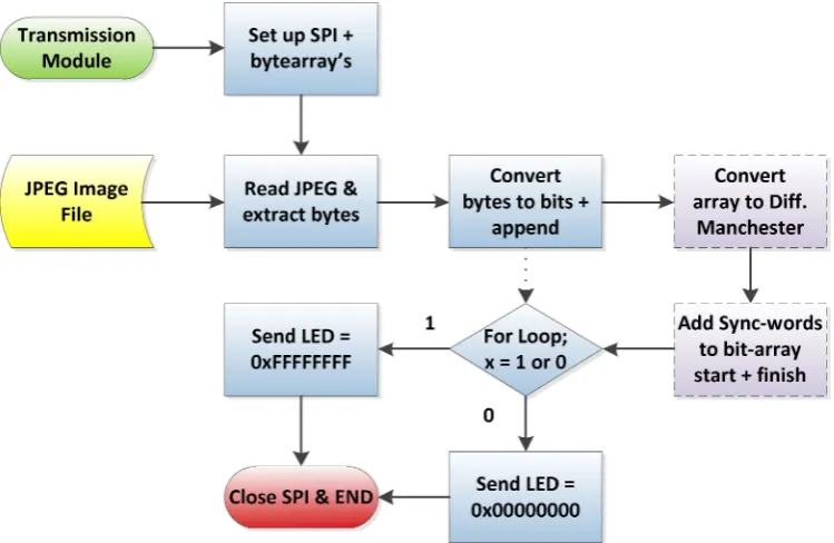
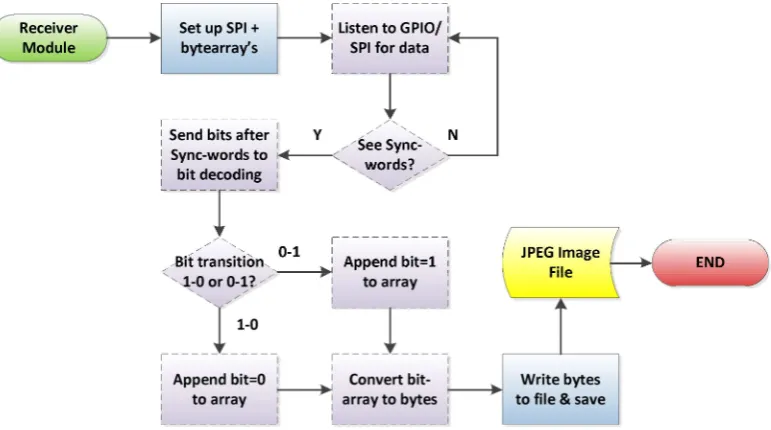
[image:37.595.111.486.499.743.2]Below is a software diagram that illustrates the intended structure of the Python code within the transmission module. The dashed boxes indicate functionality that wasn’t able to be implemented during the project timeframe, but does show the intent of the code. The dotted arrow shows that a bitstream of the file data was able to be transmitted successfully.
28
4.2.3.2 Encoding the File Data
The simplest way to encode data such that long strings of similar bits can be understood is Manchester Encoding. This method is data heavy in the fact that it transmits two bits for every one bit of data to send. For example to send a ‘1’ bit, the code must send ‘01’ and conversely to send a ‘0’, you need to send ‘10’. The benefit of this method is that the most number of the same bit type that you have together is two. If you want to send two bits such as ‘10’ the data you send is ‘0110’, so therefore each bit that you send has one state transition (from 01 or 10).
4.2.3.3 Sync-words
The sync-words help to identify the start and finish of the data file. These are applied to the bytearray once the bitstream from the file is created. They are to be transmitted as well. The sync-words should be discernible from the Differential Manchester sequence so a normal data sequence is not taken to be the finish of file sync-word. It must also be a mixture of 1’s and 0’s to prevent the receiver module starting to store data in the receiver bytearray because a false signal has been seen.
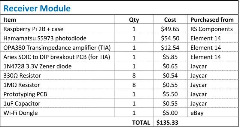
4.2.4
Cost
With a view to keeping the project accessible to students, all components were purchased from mainstream electronic outlets. A Table of the costs associated with the construction of the transmitter module is shown below.
Transmitter module
Item Qty Cost Purchased from
Raspberry Pi 2B + case 1 $49.65 RS Components APA102 LED (DotStar) 10 $7.34 Core Electronics 5050 LED Breakout boards 10 $7.40 Core Electronics 74HCT125 Quad Level Shifter 1 $2.22 Core Electronics 470Ω