Layered Steered Space-Time Codes Using Iterative Detection
Mohammed El-Hajjar, Osamah Alamri and Lajos Hanzo
School of Electronics and Computer Science, University of Southampton, SO17 1BJ, UK.Email:{meh05r,ora02r,lh}@ecs.soton.ac.uk, http://www-mobile.ecs.soton.ac.uk
Abstract— This paper presents a novel multifunctional multiple-input multiple-output (MIMO) scheme that combines the benefits of the Vertical Bell Labs Layered Space-Time (V-BLAST) scheme, of Space-Time Codes (STC) as well as of beam-forming. Further system performance improvements can be at-tained by serially concatenated convolutional encoding combined with a unity-rate code (URC) referred to as a precoder. Then, at the receiver side, iterative decoding is invoked by exchanging extrinsic information between the precoder’s decoder as well as the outer Recursive Systematic Convolutional (RSC) code’s decoder. Moreover, the convergence behaviour of the proposed system is evaluated with the aid of Extrinsic Information Transfer (EXIT) charts. Finally, we quantify the maximum achievable rate of the system based on EXIT charts and demonstrate that the iterative-detection-aided system is capable of operating within
1dB from the maximum achievable rate.
I. INTRODUCTION
Multiple-Input Multiple-Output (MIMO) schemes are capa-ble of counteracting the fundamental limitations of wireless transmissions imposed by time-varying multipath fading [1]. More explicitly, recent information theoretic studies [2, 3] have revealed that a MIMO system has a higher capacity than a single-input single-output (SISO) system. In [4], Wolniansky et al. proposed the popular multi-layer MIMO structure, known as the Vertical Bell Labs Layered Space-Time (V-BLAST) scheme. The V-BLAST receiver is capable of provid-ing a tremendous increase of a specific user’s effective bit-rate without the need for any increase in the transmitted power or the system’s bandwidth. However, its impediment is that it was not designed for exploiting transmit diversity and the decision errors of a particular antenna’s detector propagate to other bits of the multi-antenna symbol, when erroneously cancelling the effects of the sliced bits from the composite signal.
Whilst V-BLAST was designed for maximising the achiev-able multiplexing gain, Alamouti [5] discovered a witty trans-mit diversity scheme, referred to as a space-time block code (STBC), which was designed for a high diversity gain. The attractive benefits of Alamouti’s design motivated Tarokh et al. [6] to generalise Alamouti’s scheme to an arbitrary number of transmit antennas. STBC uses low-complexity linear pro-cessing at the receiver side for detecting the transmitted signals and is capable of achieving the maximum possible diversity gain. Since the V-BLAST structure is capable of achieving the maximum multiplexing gain, while the STBC scheme attains
The financial support of Vodafone under the auspices of the Dorothy Hodgkin Postgraduate Award and that of the European Union within the Newcom and Pheonix projects, and the support of EPSRC, UK is gratefully acknowledged.
the maximum antenna diversity gain, it was proposed in [7] to combine the benefits of these two techniques for the sake of providing both antenna diversity as well as spectral efficiency gains. This hybrid scheme was improved in [8] by optimising the decoding order of the different antenna layers. On the other hand, beamforming [9] constitutes an effective technique of reducing the multiple-access interference (MAI), where the antenna gain is increased in the direction of the desired user, whilst reducing the gain towards the interfering users.
Iterative decoding of spectrally efficient modulation schemes was considered by several authors [1, 10]. In [11], the employment of the turbo principle was considered for iterative soft demapping in the context of multilevel mod-ulation schemes combined with channel decoding, where a soft symbol-to-bit demapper was used between the multilevel demodulator and the binary channel decoder. In [12], rate-1 inner codes were employed for designing low complexity turbo codes suitable for bandwidth and power limited systems having stringent bit-error-rate (BER) requirements. Recently, studying the convergence behaviour of iterative decoding has attracted considerable attention. In [13], ten Brink proposed the employment of the so-called extrinsic information transfer (EXIT) characteristics between a concatenated decoder’s input and output for describing the flow of extrinsic information through the soft-in soft-out constituent decoders.
The novelty and rationale of the proposed system can be summarised as follows:
1) We amalgamate the merits of V-BLAST, STBC, and beamforming for the sake of achieving a high diversity gain, a high throughput as well as beamforming gain. The proposed scheme is referred to as a Layered Steered Space-Time Block Code (LSSTBC).
2) We propose a novel scheme for quantifying the maximum achievable rate of the system using EXIT charts. 3) Finally, iterative detection exchanging extrinsic
informa-tion between the inner unity-rate code’s (URC) decoder and the outer convolutional code’s decoder is employed and analysed using EXIT charts. The URC is capable of completely eliminating the system’s error-floor as well as operating at the lowest possible turbo-cliff SNR with-out significantly increasing the associated complexity or interleaver delay. Explicitly, the proposed iterative-detection-aided system is capable of operating within 1 dB from the maximum achievable rate obtained using the EXIT charts.
Serial−to−Parallel Converter
Beamformer ... DOA
Beamformer ... DOA Beamformer ... DOA
Beamformer ... DOA QPSK
Mapper URC
Encoder Conv.
Encoder
QPSK Demapper URC
Decoder Conv.
Decoder
STBC
. . . .
. . . .
STBC
. . . .
. . . .
Binary Source
×
×
×
× ×
×
×
×
Π
Π−1 +
+ Π
Output
W11
W1L
AA 2 AA 1
W21
W2L
W31
W3L
W41
W4L
AA 4 AA 3
c d
D
eco
d
er
L
S
S
T
BC
Hard Decision
Li,a
Li,e Li,p Lo,a
Lo,p Lo,e
Lo,i,p
x
˜
[image:2.595.129.487.54.364.2]x
Fig. 1. Schematic of the proposed iteratively detected scheme.
we introduce the proposed serially concatenated and iteratively decoded LSSTBC scheme. Section III describes the encoding and decoding processes of the LSSTBC scheme followed by Section IV that details the design and EXIT chart aided characterisation of the iterative detection scheme. Finally, the attainable performance of these schemes is studied compara-tively in Section V, followed by our conclusions in Section VI.
II. SYSTEMOVERVIEW
A high level block diagram of the proposed scheme is illustrated in Figure 1. The antenna architecture employed in Figure 1 has M = 4 transmit Antenna Arrays (AA) spaced sufficiently far apart in order to achieve transmit diversity. The L number of elements of each of the AAs are spaced at a distance of d = λ/2 for the sake of achieving beam-forming. Furthermore, the receiver is equipped with N = 4 antennas. According to Figure 1, the transmitted source bits are convolutionally encoded and then interleaved by a random bit interleaver. A 1/2-rate Recursive Systematic Convolu-tional (RSC) code was employed. After channel interleaving the symbols are precoded by a URC encoder. Then, the QPSK mapper of Figure 1 maps B channel-coded bits b=
b0, . . . , bB−1 ∈ {0,1} to a QPSK symbol x. Subsequently,
the QPSK modulated symbols are serial-to-parallel converted to two substreams so that each substream will be transmitted using twin AA aided STBC, as will be detailed in Section III. In this contribution, we consider transmissions over a temporally correlated narrowband Rayleigh fading channel
associated with a normalised Doppler frequency of fD =
fdTs= 0.01, withfdbeing the Doppler frequency andTsthe
symbol duration, where the channel coefficients are spatially independent. The complex Additive White Gaussian Noise (AWGN) ofn=nI+jnQ contaminates the received signal,
where nI and nQ are two independent zero-mean Gaussian
random variables having a variance of N0/2 per dimension,
withN0/2representing the double-sided noise power spectral
density expressed inW/Hz.
As shown in Figure 1, the received complex-valued symbols are first decoded by the LSSTBC decoder in order to produce a received symbolx˜, which is fed into the QPSK demapper. As seen in Figure 1, the URC decoder processes the information forwarded by the demapper in conjunction with the a priori information in order to generate thea posterioriprobability. Thea prioriLog-Likelihood Ratio (LLR) values of the URC decoder are subtracted from the a posteriori LLR values, provided by the Log Maximum Aposteriori Probability (MAP) algorithm, for the sake of generating the extrinsic LLR values Li,e, as seen in Figure 1. Next, the soft bits Lo,a are passed
to the convolutional decoder of Figure 1 in order to compute the a posteriori LLR values Lo,p provided by the Log
MAP algorithm for all the channel-coded bits. During the last iteration, only the LLR valuesLo,i,p of the original uncoded
the extrinsic information Lo,e, is generated by subtracting
the a priori information from the a posteriori information according to(Lo,p−Lo,a), which is then fed back to the URC
decoder as the a priori information Li,a after appropriately
reordering them using the interleaver of Figure 1.
III. LAYEREDSTEEREDSPACE-TIMEBLOCKCODES
The encoding process of the LSSTBC is illustrated in Figure 1. The QPSK modulated symbols vector x is split into two data streams, where each data stream is encoded using theG2STBC [5, 6] for transmission. Each AA employed
combined with each component STBC in Figure 1 is equipped withLelements for the sake of achieving beamforming gain. TheL-dimensional Spatio-Temporal (ST) Channel Impulse Response (CIR) vector between themth transmitter AA,m∈
[1,· · ·, M], and thenth receive antenna,n∈[1,· · ·, N], can be expressed ashnm(t) =anm(t)δ(t−τk)
= anm,0(t), . . . , anm,(L−1)(t)
T
δ(t−τk), where τk is the
signal’s delay, anm,l(t) is the CIR with respect to themnth
link and the lth element of the mth AA. Based on the assumption that the array elements are separated by half a wavelength, we have
anm(t) =αnm(t)·dnm, (1)
where αnm(t) is a Rayleigh faded envelope, dnm = [1,exp(j[πsin(ψnm)]), . . . ,exp(j[(L−1)πsin(ψnm)])]T and
ψnm is thenmth link direction of arrival (DOA).
The received baseband data matrixY can be expressed as
Y=HWX+N, (2)
whereNdenotes the Additive White Gaussian Noise (AWGN) matrix and H is an N ×M matrix whose entries are hnm.
Furthermore,W is a diagonal weight matrix whose diagonal entry wmn is the L-dimensional weight vector for the mth
beamformer AA and the nth receive antenna. Let wmn =
d†
nm, then the received signal can be expressed as
Y=LHX˜ + ˜N, (3)
whereH˜ is anN×M matrix whose entries areαnm.
Let H˜1 andH˜2 denote the specific versions of the matrix
˜
Hgenerated after setting the particular columns corresponding to layers two and one, respectively, to zero. Then,Y can be expressed as
Y=L·H˜1·x1+L·H˜2·x2+nt, (4)
where xk represents the component STBC used at layer k,
withk= 1,2.
The more beneficial decoding order of the two layers is determined on the basis of detecting the higher-power layer first for the sake of a higher correct detection probability. For simplicity, we assume that layer 1 is detected first which allows us to eliminate the interference caused by the signal of layer 2. For this reason, the decoder of layer 1 has to compute a matrix Q, so that we have Q·H˜2 = 0. Therefore, the
decoder computes an orthonormal basis for the left null space
of H2 and assigns the vectors of the basis to the rows of Q. MultiplyingQ by Y suppresses the interference of layer 2 originally imposed on layer 1 and generates the following signal:
b
Y=Q·Y = L·Q·H˜1·x1+ 0 +Q·nt = Hb ·x1+bnt. (5)
Following these operations, according to Equation (5) the decoder applies maximum likelihood STBC decoding for recovering the transmitted signals of the first layer. Then, the decoder subtracts the remodulated contribution of the decoded symbols of layer 1 from the composite twin-layer received signal. Finally, the decoder applies direct STBC decoding for the second layer, since the interference imposed by the first layer has been eliminated.
The first decoded layer has a diversity order of(2×4), while the second layer has an order of(4×4). In order to determine the more meritorious decoding order, the decoder processes the specific layer having the higher post-detection SNR, which is directly proportional to the norm of Hb. Thus, to determine the more beneficial decoding order, the decoder computes the orthonormal basis for the left null space of bothH˜1as well as
˜
H2 and then evaluates the norm of the corresponding matrix b
Hand decodes the specific layer having the higher norm first.
IV. ITERATIVEDECODING ANDEXIT CHARTANALYSIS
In the receiver, URC- and RSC-decoding are performed iteratively, as shown in Figure 1. Both of these decoders invoke the Bahl-Cocke-Jelinek-Raviv (BCJR) algorithm [14] using their bit-based trellises. All BCJR calculations are performed in the logarithmic probability domain and using an eight-entry lookup table for correcting the Jacobian approximation in the Log-MAP algorithm [1].
Extrinsic soft information, represented in the form of Log-arithmic Likelihood Ratios (LLRs), is iteratively exchanged between the URC and RSC decoding stages for the sake of assisting each other’s operation as usual and as detailed in [15]. In Figure 1, L(·) denotes the LLRs of the bits concerned, where the superscript i indicates inner precoder decoding, while o corresponds to outer RSC decoding. Additionally, a subscript denotes the dedicated role of the LLRs, witha,pand e indicating a priori, a posteriori and extrinsic information, respectively.
The concept of EXIT charts was proposed in [13] for predicting the convergence behaviour of iterative decoders, where the evolution of the input/output mutual information exchange between the inner and outer decoders in consecutive iterations was examined. The application of EXIT charts is based on two main assumptions, which are realistic when using high interleaver lengths, namely that the a prioriLLR values are fairly uncorrelated and that the Probability Density Function (PDF) of the a priori LLR values is Gaussian distributed.
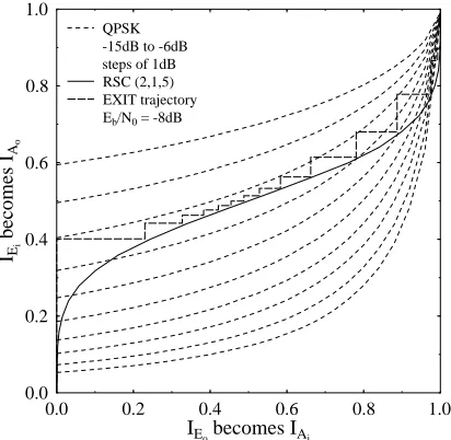
chart [13]. The x-axis represents the outer RSC decoder’s extrinsic output IEo which becomes the URC decoder’s a prioriinputIAi. Similarly, the URC decoder’s extrinsic output IEi becomes the outer RSC decoder’sa prioriinputIAo and is represented on the y-axis. Figure 2 plots the EXIT charts of the turbo-detection aided channel-coded LSSTBC scheme employing an outer 1/2-rate RSC code, the inner URC and the system parameters outlined in Table I for differentEb/N0
values. Ideally, the EXIT curve of the inner and outer decoders should only intersect at a point near the IED = 1.0 line, in order for the exchange of extrinsic information between the URC’s decoder and the RSC decoder to converge at a specific Eb/N0 value. Observe from the figure that an open
convergence tunnel [13] is formed aroundEb/N0 =−8 dB.
This implies that according to the predictions of the EXIT chart seen in Figure 2, the iterative decoding process is expected to converge at anEb/N0 value between−9 dB and
−8dB. The EXIT chart based convergence predictions can be verified by the actual iterative decoding trajectory of Figure 2, where the trajectory was recorded at Eb/N0 =−8 dB while
using an interleaver length of D = 100,000 bits. The steps seen in the figure represent the actual extrinsic information exchange between the URC’s decoder and the outer RSC channel decoder.
0.0 0.2 0.4 0.6 0.8 1.0
IEobecomes IAi
0.0 0.2 0.4 0.6 0.8 1.0
IEi
becomes
IAo
QPSK -15dB to -6dB steps of 1dB RSC (2,1,5) EXIT trajectory
Eb/N0= -8dB
Fig. 2. EXIT chart of a1/2-rate RSC channel-coded and precoded LSSTBC scheme employing Gray mapping aided QPSK, while using an interleaver length of100,000bits and the system parameters outlined in Table I.
Moreover, it was argued in [16, 17] that the maximum achievable bandwidth efficiency of the system is proportional to the code-rate, which is equal to the area under the EXIT curve of the inner code, provided that the bit stream b has independently and uniformly distributed bits as well as that the channel is the binary erasure channel, the inner code rate is 1 and the MAP algorithm is used for decoding. There is also experimental evidence that the area under the inner code’s EXIT curve approximates the code-rate well for Rayleigh and Gaussian channels as well. Assuming that the area under the
Modulation Scheme QPSK
No. of Transmitter AA 4
Number of elements per AA L
No. of Receiver Antennas 4
Channel Correlated Rayleigh Fading
Normalised Doppler
frequency 0.01
Outer channel Code RSC(2,1,5)
Generator (gr, g)=(35,23)8
Precoder URC
Generator G(D)=1/(1 +D)
Drepresents a Delay element
TABLE I SYSTEM PARAMETERS
EXIT curve of the inner decoder, i.e. the URC decoder and the QPSK demapper, is represented byA, the maximum attainable rate for the outer code is given by Rmax = A [16] at a
specific Eb/N0 value. Therefore, the maximum achievable
bandwidth efficiency becomesηmax =F×Rmax, where F
is the number of bits per symbol in the proposed scheme. The maximu achievable rate of the QPSK modulation assisted LSSTBC scheme computed based on the EXIT charts is shown in Figure 3. At a bandwidth efficiency ofη = 2 bit/s/Hz, the capacity limits forL= 4 is Eb/N0 ≈ −9 dB as depicted in
Figure 3.
-15 -10 -5 0 5 10
Eb/N0[dB]
0.0 0.5 1.0 1.5 2.0 2.5 3.0 3.5 4.0 4.5 5.0
[b/s/Hz]
[image:4.595.329.547.51.174.2]Maximum Achievable Rate
Fig. 3. Maximum Achievable rate of the LSSTBC system while employing
L= 4and the system parameters outlined in Table I.
V. PERFORMANCERESULTS
In this section, we present the results of the proposed system employingM = 4transmit AAs andN = 4receive antennas, while using the parameters outlined in Table I.
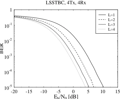
In Figure 4 we plot the BER versus Eb/N0 performance
of the LSSTBC scheme, where Eb denotes the energy per
bit and N0 denotes the double sided noise power spectral
[image:4.595.61.267.356.557.2]example, where most of the diversity gain is achieved while employing two transmit antennas, since upon increasing the number of transmit antennas further, the additional transmit diversity gain tends to remain modest.
-20 -15 -10 -5 0 5 10 15
Eb/N0[dB]
10-5 10-4 10-3 10-2 10-1 1
BER
LSSTBC, 4Tx, 4Rx
[image:5.595.63.266.120.288.2]L=1 L=2 L=3 L=4
Fig. 4. BER performance of the LSSTBC system using a variable number of elementsLper AA and the system parameters outlined in Table I.
Figure 5 compares the attainable performance of the pro-posed1/2-rate RSC-coded LSSTBC scheme employingL= 4 for a variable number of iterations. In Figure 5, an interleaver depth of D = 105 bits was employed and a normalised
Doppler frequency of fD = 0.01 was used. The system’s
throughput in this case is 2 bits/sec/Hz. As suggested by the EXIT chart analysis of Figure 2, the proposed system converges at anEb/N0of−8dB after14iterations. Explicitly,
Figure 5 demonstrates that a coding advantage of about12dB was achieved at a BER of 10−5 after I = 14 iterations by
the 1/2-rate RSC-coded QPSK modulated LSSTBC system over the uncoded LSSTBC-QPSK scheme. Furthermore, we observe from Figure 5 that the system’s performance is within 1 dB from the maximum achievable rate obtained from the EXIT charts.
-12 -10 -8 -6 -4 -2 0 2 4
Eb/N0[dB]
10-5 10-4 10-3 10-2 10-1 1
BER
UnCoded System Coded System 0 iter 1 iter 2 iter 7 iter 14 iter
maximum
achievable
[image:5.595.63.265.534.689.2]rate
Fig. 5. Performance comparison of QPSK modulated convolutional-coded LSSTBC scheme, while using a URC precoder, an interleaver length of
100,000bits and the system parameters outlined in Table I.
VI. CONCLUSION
In this contribution we presented a generalised multifunc-tional MIMO scheme that combines the benefits of V-BLAST, STBC and beamforming. We also proposed a novel scheme for quantifying the maximum achievable rate of the system using EXIT charts. The generalised multifunctional MIMO scheme was combined with a serially concatenated and iteratively decoded convolutional code and URC to operate within1 dB from the maximum achievable rate obtained using EXIT charts. Our future research will consider the design of an irregular convolutional code designed for attaining a near-capacity performance by the proposed system.
REFERENCES
[1] L. Hanzo, T. H. Liew, and B. L. Yeap, Turbo coding, turbo
equali-sation and space time coding: for transmission over fading channels.
Chichester, UK: Wiley: IEEE Press, 2002.
[2] G. Foschini and M. Gans, “On Limits of wireless communications in a fading environment when using multiple antennas,” Kluwer Academic
Publishers, Wireless Personal Communications, pp. 311–335, 1998.
[3] E. Telatar, “Capacity of Multi-Antenna Gaussian Channels,” European
Transactions on Telecommunications, vol. 10, pp. 585–595, Nov./Dec.
1999.
[4] P. Wolniansky, G. Foschini, G. Golden, and R. Valenzuela, “V-BLAST: an architecture for realizing very high data rates over the rich-scattering wireless channel,” in International Symposium on Signals, Systems, and
Electronics, (Pisa), pp. 295–300, September 1998.
[5] S. Alamouti, “A simple transmit diversity technique for wireless commu-nications,” IEEE Journal on Selected Areas in Communications, vol. 16, no. 8, pp. 1451–1458, 1998.
[6] V. Tarokh, H. Jafarkhani, and A. Calderbank, “Space-time block codes from orthogonal designs,” IEEE Transactions on Information Theory, vol. 45, no. 5, pp. 1456–1467, 1999.
[7] V. Tarokh, A. Naguib, N. Seshadri, and A. Calderbank, “Combined array processing and space-time coding,” IEEE Transactions on Information
Theory, vol. 45, no. 4, pp. 1121–1128, 1999.
[8] M. Tao and R. Cheng, “Generalized layered space-time codes for high data rate wireless communications,” IEEE Transactions on Wireless
Communications, vol. 3, no. 4, pp. 1067–1075, 2004.
[9] J. Blogh and L. Hanzo, Third-generation systems and intelligent wireless
networking: smart antennas and adaptive modulation. John Wiley &
Sons - IEEE Press, 2002.
[10] S. Le Goff, A. Glavieux, and C. Berrou, “Turbo-codes and high spectral efficiency modulation,” in IEEE International Conference on
Communications, (New Orleans, LA), pp. 645–649, 1994.
[11] S. ten Brink, J. Speidel, and R.-H. Yan, “Iterative demapping and de-coding for multilevel modulation,” in IEEE Global Telecommunications
Conference (GLOBCOM), vol. 1, (Sydney,NSW), pp. 579–584, 1998.
[12] D. Divsalar, S. Dolinar, and F. Pollara, “Serial concatenated trellis coded modulation with rate-1 inner code,” in IEEE Global Telecommunications
Conference (GLOBECOM), vol. 2, (San Francisco, CA), pp. 777–782,
2000.
[13] S. ten Brink, “Designing Iterative Decoding Schemes with the Extrinsic Information Transfer Chart,” AEU¨ International Journal of Electronics and Communications, vol. 54, pp. 389–398, Nov 2000.
[14] L. Bahl, J. Cocke, F. Jelinek, and J. Raviv, “Optimal decoding of linear codes for minimizing symbol error rate (Corresp.),” IEEE Transactions
on Information Theory, vol. 20, no. 2, pp. 284–287, 1974.
[15] S. Benedetto and G. Montorsi, “Serial concatenation of block and convolutional codes,” Electronics Letters, vol. 32, pp. 887–888, May 1996.
[16] M. T ¨uchler, “Design of serially concatenated systems depending on the block length,” IEEE Transactions on Communications, vol. 52, no. 2, pp. 209–218, 2004.
[17] A. Ashikhmin, G. Kramer, and S. ten Brink, “Extrinsic information transfer functions: model and erasure channel properties,” IEEE