Flexible Robot Platform
For
Autonomous Research
By
David John Hall (BComp)
A dissertation submitted to the School of Computing
in partial fulfilment of the requirements for the degree of
Bachelor of Computing with Honours
University of Tasmania
Declaration
I, David Hall declare that this thesis contains no material, which has been accepted for the award of any other degree or diploma in any tertiary institution. To my
knowledge and belief, this thesis contains no material previously published or written by another person except where due reference is made in the text of the thesis.
Signed: Date:
Abstract
Acknowledgements
I would like to thank the following people for their help throughout the year:
My supervisors Dr Daniel Rolf and Dr Waheed Hugrass for all their patience, support and advice.
Mr Tony Gray for his assistance in ordering and collecting all of the parts for the project.
Andrew Spilling for his repeated help booking the seminar room.
My friend James for his ongoing suggestions and ideas.
Table of Contents
DECLARATION ... II ABSTRACT ... III ACKNOWLEDGEMENTS ... IV TABLE OF CONTENTS ...V LIST OF FIGURES...VII LIST OF TABLES... VIII LIST OF EQUATIONS ... IX
CHAPTER 1 INTRODUCTION ...1
1.1 BACKGROUND...1
1.2 HYPOTHESIS...2
1.3 APPROACH...2
CHAPTER 2 LITERATURE REVIEW ...3
2.1 INTRODUCTION...3
2.2 MOBILE ROBOTS...4
2.2.1 Airborne...4
2.2.2 Aquatic...4
2.2.3 Space...4
2.2.4 Terrestrial...4
2.3 TERRESTRIAL MOBILE ROBOT SENSORS...5
2.3.1 Tactile Sensors...5
2.3.2 Ultrasonic Sensors ...5
2.3.3 Infrared Sensors ...6
2.3.4 Laser Sensors...6
2.3.5 Digital Compass ...7
2.3.6 Encoders ...7
2.4 MOBILE ROBOT FLEXIBILITY...8
2.5 TERRESTRIAL MOBILE ROBOT PLATFORMS...9
2.5.1 ActivMedia Robotics Pioneer 1 ...10
2.5.2 Evolution Robotics ER1 Personal Robot System ...11
2.5.3 K-Team Corporation Khepera II...11
2.5.4 Lego™ MindStorms...12
2.5.5 Nomadic Technologies Super Scout II ...13
2.5.6 Micro Robot Alice ...13
2.6 ROBOT ALGORITHM TESTING...14
2.6.1 Real World...14
2.6.2 Simulated ...14
2.6.3 Hybrid...14
CHAPTER 3 METHODOLOGY ...15
3.1 EXISTING MOBILE ROBOT PLATFORMS...15
3.2 IMPLEMENTATION...17
3.2.1 Design...17
3.2.2 Components ...18
3.2.3 Construction ...22
3.2.4 OOPic API...24
3.2.5 Flexible Robot Platform ...28
CHAPTER 4 TESTING AND ANALYSIS ...29
4.1 FLEXIBILITY FEATURE COMPARISON...29
4.1.1 Procedure ...29
4.1.2 Results...30
4.2 STRAIGHT LINE TEST...31
4.2.1 Procedure ...31
4.2.2 Results Run 1 ...35
4.2.3 Results Run 2 ...38
4.2.4 Analysis...41
4.3 UMBMARK TEST...42
4.3.1 Procedure ...42
4.3.2 Results...45
4.3.3 Analysis...46
4.4 MOBILE PLATFORM MOTION COMPARISON...47
4.4.1 Classification technique ...48
4.4.2 Result ...48
4.4.3 Analysis...49
CHAPTER 5 CONCLUSION ...50
CHAPTER 6 FUTURE WORK...52
6.1 RE-CONFIGURABLE CHASSIS AND DRIVE SYSTEM...52
6.2 HIGHER COMPLEXITY ALGORITHMS...52
6.3 LINKING TO OPEN SOURCE SOFTWARE...52
REFERENCES ...53
APPENDIX A STRAIGHT LINE TEST DATA...58
APPENDIX B UMBMARK DATA ...62
APPENDIX C MOBILE ROBOT MOTION CAPABILITIES...63
APPENDIX D POWER DISTRIBUTION BOARD SPECIFICATIONS ...64
APPENDIX E COMPACT DISC ...65
List of Figures
FIGURE 2.1SWITCH, STRAIN GAUGE AND PIEZOELECTRIC SENSORS...5
FIGURE 2.2SRF04ULTRASONIC RANGEFINDER MODULE AND DIAGRAM OF OPERATION...5
FIGURE 2.3GP2D12INFRARED RANGEFINDER AND DIAGRAM OF OPERATION...6
FIGURE 2.4CMPS03DIGITAL COMPASS AND FLUX IN UNSATURATED (TOP) AND SATURATED (BOTTOM) CORE...7
FIGURE 2.5HEDS-5500OPTICAL ENCODER AND DIAGRAM OF OPERATION...7
FIGURE 2.6TERRESTRIAL MOBILE ROBOT PLATFORMS...10
FIGURE 3.1FLEXIBILITY FACTORS IN MOBILE ROBOTS...16
FIGURE 3.2FLEXIBLE ROBOT PLATFORM BLOCK DIAGRAM...18
FIGURE 3.3FRPCOMPONENT CONNECTIONS...22
FIGURE 3.4FLEXIBLE ROBOT PLATFORM SENSOR MOUNTING...23
FIGURE 3.5FLEXIBLE ROBOT PLATFORM COMPONENT MOUNTING...24
FIGURE 3.6SIMPLIFIED DIAGRAM OF OOPIC API ...26
FIGURE 3.7THE FLEXIBLE ROBOT PLATFORM...28
FIGURE 4.1STRAIGHT LINE EXPERIMENT PSEUDO-CODE...33
FIGURE 4.2STRAIGHT LINE EXPERIMENT PROCEDURE...34
FIGURE 4.3EXPERIMENT AREA SETUP...35
FIGURE 4.4STRAIGHT LINE TEST, EXPERIMENTS A,B&C ...37
FIGURE 4.5STRAIGHT LINE TEST:EXPERIMENT ARUN 2 ...39
FIGURE 4.6STRAIGHT LINE TEST:EXPERIMENT BRUN 2...40
FIGURE 4.7STRAIGHT LINE TEST:EXPERIMENT CRUN 2...40
FIGURE 4.8SUMMARY OF THE UMBMARK PROCEDURE (ADAPTED FROM (BORENSTEIN,JOHANN & FENG 1995, P.7))...43
FIGURE 4.9UMBMARK SQUARE PATH AND ASSOCIATED ERROR (ADAPTED FROM (BORENSTEIN,JOHANN &FENG 1995, P.5)) ...43
FIGURE 4.10RETURN POSITION ERROR FOR FLEXIBLE ROBOT PLATFORM...46
List of Tables
TABLE 1MOBILE ROBOT PLATFORM ADVANTAGES AND DISADVANTAGES...16
TABLE 2FLEXIBILITY FACTOR DEFINITIONS...29
TABLE 3TERRESTRIAL MOBILE ROBOTS AND THEIR FLEXIBILITY CHARACTERISTICS...30
TABLE 4STRAIGHT LINE TEST STATISTICS WITH PIONEER 1(IBEANUSI ET AL 1999) ...36
TABLE 5STRAIGHT LINE TEST STATISTICS WITH FRP RUN 1...36
TABLE 6STRAIGHT LINE TEST STATISTICS WITH FRP RUN 2...38
TABLE 7UMBMARK RESULTS FROM FLEXIBLE ROBOT PLATFORM AND TRCLABMATE (BORENSTEIN, JOHANN &FENG 1995)...45
List of Equations
EQUATION 1FRP CALIBRATION...32
EQUATION 2MEAN DISTANCE...35
EQUATION 3STANDARD DEVIATION...35
EQUATION 4STUDENTS T STATISTIC...35
EQUATION 5UMBMARK:RETURN POSITION ERROR...43
EQUATION 6UMBMARK:CENTRES OF GRAVITY...44
EQUATION 7UMBMARK:ABSOLUTE OFFSETS...44
Chapter 1
Introduction
1.1 Background
Recently the field of mobile robotics has become a focus of a great deal of research, with many academic institutions worldwide developing new algorithms and
technologies. With the volumes of research being undertaken in the field, it is becoming increasingly popular to develop and test new algorithms for mobile robots using simulation tools. They provide researchers with many plausible and enticing benefits, such as low cost and a high speed of development. They can simply test their algorithms on a regular computer and gather results.
Simulation has many benefits, however, they struggle to model the real world accurately and as a consequence algorithms which work well in a simulation, completely fail when applied in the real world. Implementing algorithms on real world mobile robots has been found to be very successful, providing an excellent indication of the success or validity of an algorithm. Traditionally testing robots in the real world has involved a process of creating a mobile robot to test a specific algorithm. The process of building the new robot and then testing an algorithm can be an extremely time consuming process. For example, testing an autonomous
underwater vehicle requires a very long period for testing, as the robot must be tested in water it becomes difficult to access and monitor during experiments. Constructing a mobile robot can also be very expensive and if the robot is too inflexible to be used for other projects after a certain algorithm has been tested, building the mobile robot often cannot be justified.
1.2 Hypothesis
It would be beneficial to mobile robot research if more algorithms could be tested in the real world. It is thought that a flexible robot platform, designed to be used for different applications, would allow more mobile robot algorithms to be tested in the real world. In an attempt to minimize the difficulties in testing mobile robot
algorithms in the real world, this thesis aims to investigate the hypothesis:
That it is possible to create a mobile robot platform, with the flexibility to test a variety of algorithms.
Stemming from this hypothesis this thesis also begins to investigate the possibility of utilizing a flexible mobile robot to implement algorithms for different kinds of mobile robot platforms.
1.3 Approach
Chapter 2
Literature Review
2.1 Introduction
The following literature review aims to provide an introduction to robots and more specifically mobile robots and the sensors they commonly use. Also to examine previous research into the inclusion of flexibility in robotic platforms, an analysis of terrestrial mobile robots commonly used for research and an examination of the methods used to test algorithms for mobile robots.The Encyclopaedia Britannica describes a robot as;
“Any automatically operated machine that replaces human effort, though it may not look much like a human being or function in a humanlike manner”(2005).
This description fits all robots ranging from an automatic conveyor belt, such as those found at supermarkets, to a fully autonomous robot from a functional perspective. Physically robots are a collection of sensors, processors and
manipulators which allow a robot to perform its function. Systematically, sensors provide input to a robot about both itself and its environment. Processing determines what to output and manipulators provide the robot’s output.
2.2 Mobile Robots
There are several different kinds of mobile robot platforms. Many mobile robot platforms are similar to existing vehicles such as cars, boats or aeroplanes. However, mobile robots also take on different or innovative forms which would not be
considered for use for human travel. Mobile robots can be categorised into the following (Dudek & Jenkin 2000):
2.2.1 Airborne
Airborne robots usually take the form of traditional aircraft or helicopters, however, they may also take other forms including parachutes, dirigibles or even rockets (for example a cruise missile). Flying robots usually require constant momentum or drive to remain airborne, which affects the way that they are controlled. Airborne
platforms share some control properties with aquatic platforms due to the fact that their locomotion is not based on contact with stationary objects or terrain.
2.2.2 Aquatic
Aquatic robots operate either in or on water. Aquatic robots are more commonly submarine, although surface robots are still used. Aquatic robots have mainly been used for marine research to access underwater areas that are not easily reached by humans. For example, robotic submarines or autonomous underwater vehicles can endure deep water missions for much longer than manned submarines.
2.2.3 Space
Robots in space are unique in that they must operate in zero or microgravity. Also, their form is affected less by the environment and more by the robot’s function. However, space robots often need to be small and light to reduce the cost of getting them into orbit. A satellite which can automatically hold or change position is an example of a mobile robot.
2.2.4 Terrestrial
improvements in technology. Terrestrial robots also take the form of everyday vehicles such as cars and tracked vehicles like excavators.
2.3 Terrestrial Mobile Robot Sensors
Mobile robots make use of a variety of different sensors in order to derive
information about themselves and their environment. Sensors which are commonly used by terrestrial mobile robots have been examined.
[image:14.595.139.521.225.353.2]2.3.1 Tactile Sensors
Figure 2.1 Switch, strain gauge and piezoelectric sensors
Tactile sensors allow the detection of physical objects. The simplest of tactile sensors simply close a switch when contact is made. More sophisticated sensors provide information on the strength or amplitude of contact. Common sophisticated tactile sensors consist of strain gauges which vary output depending on the level of
deformation of the sensor and piezoelectric transducers which provide varied voltage bursts depending on the deformation. (Nehmzow 2003, pp. 26-7)
2.3.2 Ultrasonic Sensors
Figure 2.2 SRF04 Ultrasonic rangefinder module and diagram of operation Transmitter
Receiver
[image:14.595.156.517.553.718.2]An ultrasonic sensor is made up of one or more transducers and some control circuitry. The sensor can detect whether there is an object in front of it and how far away it is. The sensor works by sending out a high frequency ‘ping’ and then listening for the reflection of the ‘ping’ with the same or another transducer. The longer the ‘ping’ takes to return to the sensor the further away the object is assumed to be. (McComb 2001, p. 633)
[image:15.595.149.515.223.375.2]2.3.3 Infrared Sensors
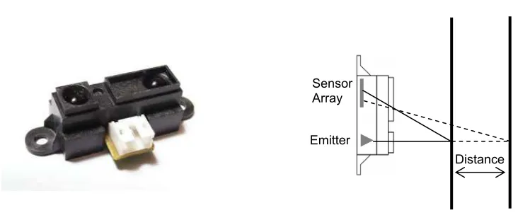
Figure 2.3 GP2D12 Infrared rangefinder and diagram of operation
Infrared sensors consist of an Infrared (IR) emitter (usually an IR Light Emitting Diode) and one or more IR sensors. Simple IR sensors simply register if the IR signal is detected, however IR rangefinders utilise an array of IR sensors. The distance of an object from the sensor can be determined through triangulation by sensing which element of the array is illuminated with reflected IR light. Different elements of the IR sensor array are illuminated due to the changing angle of the reflected light with distance from the sensor module. (Nehmzow 2003, pp. 27-8)
2.3.4 Laser Sensors
Laser rangefinders can detect the distance of objects using three methods. These methods are triangulation, time-of-flight and phase-based. Triangulation works in the same way as the infrared sensor, however makes use of laser light. Time-of-flight works on the same principles as ultrasonic sensors, determining distance from the time taken for the signal to return. Phased-based rangefinders determine the distance of an object by changes in the phase of the reflected light. Laser sensors are also referred to as LIDAR (light detection and ranging). (Dudek & Jenkin 2000, pp. 67-8)
Sensor Array
Emitter
2.3.5 Digital Compass
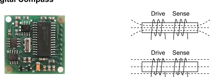
Figure 2.4 CMPS03 Digital Compass and flux in unsaturated (top) and saturated (bottom) core
A digital compass measures the horizontal component of the earth’s magnetic field. There are five main compass technologies utilised in robotics: Mechanical, Fluxgate, Hall-effect, Magneto-resistive and Magneto-elastic. The most commonly used are Fluxgate compasses which measure the earth’s magnetic field using a controlled electromagnet. A Fluxgate compass consists of a drive and sensing coil on a common core. By alternately driving the drive coil (altering the flux through the core) a
voltage is induced in the sensing coil which varies depending on the ambient
magnetic field. Two cores are required to sense north. (Borenstein, J, Everett & Feng 1996; Nehmzow 2003)
2.3.6 Encoders
Figure 2.5 HEDS-5500 Optical Encoder and diagram of operation
Encoders determine the amount of revolution of a shaft by having a disc with a specific pattern (code wheel) with which a sensor produces a signal of pulses for each part rotation of the shaft. The amount of rotation in the shaft can be determined by counting the number of pulses. The sensor for the pattern on the disc is usually a light sensor, however contact or hall-effect sensors can also be used. (Borenstein, J, Everett & Feng 1996, pp. 13-7)
Drive Sense
Drive Sense
Emitter Receiver
[image:16.595.152.529.448.571.2]2.4 Mobile Robot Flexibility
Recently the creation of mobile robot platforms which are flexible has become increasingly desirable, due to its advantages to aspects of development such as
lowering cost and shortening implementation times, as well as becoming increasingly viable due to new technologies and cheaper, more powerful components. Previous research into creating flexible robot platforms has mainly had flexibility as a
secondary goal for the platform being developed, however recent research has had a greater focus on the flexibility of mobile robot platforms.
Gerecke and others required a robotic platform which was flexible enough for use in teaching and research endeavours. In order to try and achieve this goal they are developing a mobile robot platform (MoRob) and have identified several
requirements for their platform to be successful. These include a comprehensive application program interface (API), interfaces and libraries, a variety of modules for sensing and control and comprehensive documentation (Gerecke, Hohmann & Wagner 2003; Wagner et al. 2004).
A researcher at the Fraunhofer Institute for Autonomous learning has developed a modular drive system for a mobile robot platform which allows the robot to be changed between an omni-directional and differential drive system. The system is made highly versatile due to this modularity and increases the variety of tasks which it can undertake (Bose 2004).
Researchers who have developed an autonomous two wheel drive tractor have found that by allowing their platform to accept new sensors and using a relatively powerful computer for processing their platform has been highly flexible. Being able to support a number of concurrent and diverse research projects (Will et al. 1998).
Also in order to develop a controller for creating robots with the flexibility needed for education and research, Loose and others have created a robot controller
(RCUBE). The unit is modular and allows the connection of sensors and actuators, as well as being cost effective and providing sufficient processing power for various applications (2004).
Flexibility has also formed an essential aspect to enable a variety of research directions for a set of low cost robots called CotsBots developed at the Berkeley Sensor and Actuator Center. The CotsBots achieve flexibility through the ability to interface with new sensors, and TinyOS an open source, modular operating system with a CotsBots API (Bergbreiter & Pister 2003).
From the research examined it is possible to identify some commonly cited factors which have made the platform under development by a particular researcher more flexible. All of the platforms developed have the ability to easily add new sensors to the platform. The majority of these platforms also have a developed API and low cost. Other less cited factors were detailed documentation, re-configurable chassis and the use of off-the-shelf components.
2.5 Terrestrial Mobile Robot Platforms
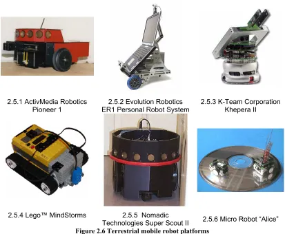
2.5.1 ActivMedia Robotics Pioneer 1
2.5.2 Evolution Robotics ER1 Personal Robot System
2.5.3 K-Team Corporation Khepera II
2.5.4 Lego™ MindStorms 2.5.5 Nomadic
[image:19.595.127.540.72.412.2]Technologies Super Scout II 2.5.6 Micro Robot “Alice”
Figure 2.6 Terrestrial mobile robot platforms
2.5.1 ActivMedia Robotics Pioneer 1
2.5.1.1 About the platform
The Pioneer 1 is a robot platform produced by ActivMedia Robotics. The Pioneer 1 robot has been very popular for use in research at all levels and has several new versions and variations. The platform is relatively expensive costing around three thousand dollars (Outfitting A Robot Laboratory). The Pioneer 1 has a differential drive system with a real wheel for stability. The platform also incorporates 7
ultrasonic sensors in an array on the front of the robot for environment sensing. The platform can also interface with additional sensors and hardware such as a laptop for increased functionality. In addition the Pioneer 1 platform has an extensively
developed API which allows the robot to be easily programmed and also simulated for program development. (ActivMedia Robotics)
2.5.1.2 Platform use
Intelligence’s annual robot competition. The robot platform had to be programmed to handle problems such as crowd navigation (Maxwell & Meeden 2000). Also, the platform has been used in more cutting edge research by Thrun and others for 3D real-time mapping with multiple robots (2000). Ibeanusi and others have also used the Pioneer 1 platform to research dead reckoning and the extent to which sonar can be used to increase the robot’s navigational accuracy (1999).
2.5.2 Evolution Robotics ER1 Personal Robot System
2.5.2.1 About the platform
The ER1 Personal Robot System (ER1) is produced by Evolution Robotics. The platform is moderately priced at around seven hundred dollars, not including an additional laptop that is required by the platform. The ER1 utilises a differential drive system for locomotion and uses a webcam for navigation. An API allows control of the robot and also includes functionality for vision based object
recognition and navigation. Analogue and digital input/output (I/O) lines are also provided for interfacing additional hardware. The main feature of this platform is its reconfigurable chassis which allows the robot to be reconfigured for a particular application. (ER1 Personal Robot System 2005)
2.5.2.2 Platform use
The ER1 robot has been used by researchers at the University of Georgia for research into the development of robotic wheelchairs. An advantage provided by the ER1 was that the chassis could be configured to roughly match that of an electric wheel chair (Ono, Uchiyama & Potter 2004).While the platform is more powerful due to the use of a laptop for processing and control, it has been found to have limited sensing capabilities and a lack of flexibility within its API (Gerecke, Hohmann & Wagner 2003).
2.5.3 K-Team Corporation Khepera II
2.5.3.1 About the platform
a differential drive system. Also included are 8 built in infrared sensors and an onboard processor for control. Three analogue inputs are also provided for additional sensors as well as stackable boards to enhance functionality. In addition K-Team provides an extensive API and simulation tools for the robot platform. (K-Team Corporation 2005)
2.5.3.2 Platform use
The platform’s small size makes it ideal for use on a desk top and it is sophisticated enough for many research tasks. The platform has been used in an undergraduate curriculum at California State University USA as part of research into using robots as a learning tool (Challinger 2005). Dozier has also used the Khepera II robot platform to implement a new method of teaching neural networks (Dozier 2001).
2.5.4 Lego™ MindStorms
2.5.4.1 About the platform
Mindstorms™ is a robotics kit produced by Lego™ (Lego(tm) Mindstorms(tm) 2005) and is popular due to its relatively low cost of around three hundred dollars. The platform is structured around an Robotic Command Explorer (RCX) ‘brick’
controller which contains a programmable controller and battery unit. The relatively small RCX unit can have Lego™ pieces attached to it to construct a robot of any desired chassis configuration. The RCX supports three inputs and three outputs, accepting three proprietary Lego™ sensors, a light sensor, temperature sensor and touch switch. The RCX outputs can be used to control Lego™ motors.
2.5.4.2 Platform use
The two main advantages of the Mindstorms robot platform are its low cost and re-configurability. However, the platform is restricted by the low processing capabilities of its controller, the inability to interface third party hardware and the limited
2.5.5 Nomadic Technologies Super Scout II
2.5.5.1 About the platform
The Super Scout II robot platform was sold commercially by Nomadic Technologies. Although the company has ceased operations, the platform is still used by various organisations for research. There is now an open source project (Sprouse) supporting the robot platform. The Super Scout II is a differential drive robot platform with 16 sonar sensors mounted in an array over 360 degrees around the robot. The robot has an onboard computer with hard drive for control and has an API which can be programmed using the C or C++ programming languages.
2.5.5.2 Platform use
The platform has been used by the University of North Dakota for their entry in the American Association for Artificial Intelligence's annual robot competition,
undertaking navigational and recognition tasks (Maxwell & Meeden 2000). The platform has a greater processing ability than most platforms which makes it able to undertake a greater variety of algorithms. The Super Scout II has also been used more recently for cooperative soccer playing robots using artificial intelligence (Lima & Custódio 2004).
2.5.6 Micro Robot Alice
2.5.6.1 About the platform
Alice is a micro robot developed at the Swiss Federal Institute of technology Lausanne for research and education purposes (Caprari et al. 1998).The Alice robot is available commercially from K-Team Corporation, for around six hundred dollars (K-Team Corporation 2005). The most unique feature of the platform is its unique size of approximately 2x2x2cm. The platform also has 4 infrared proximity sensors and a small 4 MHz microcontroller. Also a radio module can be added to the platform for control from a PC.
2.5.6.2 Platform use
main advantages of the Alice robot are that it is low cost, has a low power
consumption and some ability for the addition of small modules (Caprari et al. 1998).
2.6 Robot Algorithm Testing
There are three main methods used for the testing of robotic algorithms. These are real world, simulated and hybrid testing. Each method has certain strengths and weaknesses which are examined further.
2.6.1 Real World
Real world testing involves implementing an algorithm on a physical robot platform such as those in Figure 2.6. The success of the algorithm can then be evaluated by seeing how it performs on the robot in the real world. The advantage of real world testing is that an algorithm can be confirmed to work. The disadvantages of real world testing are that it can be time consuming to test algorithms and costly (Michel 2004).
2.6.2 Simulated
Simulation involves simulating a robot platform in a virtual world to test algorithms. The advantages of this are that algorithms can be quickly tested (faster than real time) and cost less than real robots (Lee, Nehmzow & Hubbold 1998; Michel 2004). However, the main disadvantage of simulation is that due to the fact that simulators cannot model the real world exactly, algorithms which work in simulations can completely fail in the real world (Brooks 1992). This has limited the effectiveness of simulations (Lee, Nehmzow & Hubbold 1998).
2.6.3 Hybrid
Chapter 3
Methodology
This chapter details the process undertaken to create the Flexible Robot Platform (FRP). This process consists of two stages, the examination of existing platforms to determine desirable characteristics for a flexible mobile robot platform and the implementation of a mobile robot platform (the FRP) which possesses as many of the identified characteristics as possible.
3.1 Existing Mobile Robot Platforms
In order to construct a flexible mobile robot platform, the features or factors which make a mobile robot flexible needed to be determined. Previous research (see section 2.4) has identified several factors which increase the flexibility of a mobile robot platform. The factors are summarised as follows:
• Ability to interface 3rd party components (sensors & actuators) • Well developed and documented API
• Re-configurable chassis • Low cost
• Modularity
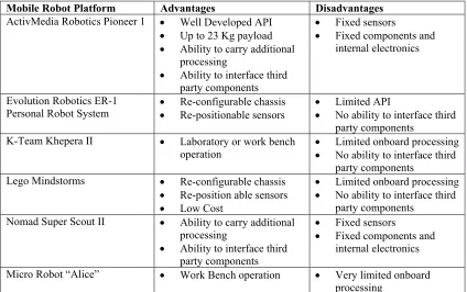
Mobile Robot Platform Advantages Disadvantages ActivMedia Robotics Pioneer 1 • Well Developed API
• Up to 23 Kg payload
• Ability to carry additional processing
• Ability to interface third party components
• Fixed sensors
• Fixed components and internal electronics
Evolution Robotics ER-1 Personal Robot System
• Re-configurable chassis
• Re-positionable sensors
• Limited API
• No ability to interface third party components
K-Team Khepera II • Laboratory or work bench operation
• Limited onboard processing
• No ability to interface third party components
Lego Mindstorms • Re-configurable chassis
• Re-position able sensors
• Low Cost
• Limited onboard processing
• No ability to interface third party components
Nomad Super Scout II • Ability to carry additional processing
• Ability to interface third party components
• Fixed sensors
• Fixed components and internal electronics
[image:25.595.122.546.85.351.2]Micro Robot “Alice” • Work Bench operation • Very limited onboard processing
Table 1 Mobile robot platform advantages and disadvantages
From the factors in Table 1 and those identified from previous research, a new summary of the factors of flexibility in mobile robots has been produced (Figure 3.1). The modularity of a mobile robot platform was not included as it was deemed to be an inherent property of other factors.
• Ability to carry additional processing • Ability to interface third party components • Laboratory or work bench operation • Large payload capacity
• Low cost
• Re-configurable chassis • Re-positionable sensors
• Well developed and documented API
Figure 3.1 Flexibility factors in mobile robots
to analyse the flexibility of the created platform (FRP) and other mobile robot platforms.
When attempting to create a mobile robot platform with all of the factors in Figure 3.1 the factors can conflict with each other. This occurs due to the counter-productive nature of some of these factors. For example a robot which has an extremely
configurable chassis may as a result not be able to carry a particularly large payload due to the chassis of the robot having less structural integrity. This means that when determining the final design of a mobile robot platform, some compromises may need to be made to ensure a platform is as flexible as possible without unduly impairing the other aspects of the robot platform. One factor which has an overbearing influence on the ability to include other factors into a mobile robot design is low cost. By limiting the cost of a mobile robot design it may not be possible to satisfy all of the factors to create a flexible robot platform. For example an entirely re-configurable chassis may cost considerably more than one that is only partially configurable. As a result compromises may need to be made to designs in order to create a balance amongst all the flexibility factors.
3.2 Implementation
3.2.1 Design
Having thoroughly investigated the designs of existing mobile robot platforms, the design for the ‘flexible robot platform’ was produced. The platform needed to be as flexible as possible within the budget and time constraints. The project had a small budget of around one thousand five hundred dollars and was to be constructed and tested over a period of 2 semesters (9 months). Initially existing commercially available robot platforms such as the Pioneer robots from ActivMedia Robotics (ActivMedia Robotics) were investigated. However these were found to be unsuitable for two reasons. Firstly, the platforms sensors are in fixed positions making the platforms too inflexible for the project. Secondly, the platforms are relatively expensive and would not allow the developed platform to have a low cost.
sub-components allowed the utilisation of already developed and supported
components and meant that the platform could be more easily constructed within the projects timeframe.
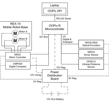
The design of the flexible robot platform is centred around the electrical and data connections of the components, as the platform allows for the component’s physical configuration to be changed into any desired state. Each of the components selected for the flexible robot platform are shown in Figure 3.2 and are explained in detail in section 3.2.2.
3.2.2 Components
The Flexible Robot Platform’s components can be divided into three main
[image:27.595.148.519.378.723.2]categories, chassis and power, processing and control and sensors. Figure 3.2 shows how each of the components are connected with the FRP.
Figure 3.2 Flexible Robot Platform Block Diagram SRF04 Sonar Sensor
GP2D12 Infrared Distance
Sensor HEDS-5505 Optical Encoders
Power Distribution
Board OOPic-R Microcontroller
I/O Digital & Analogue
Laptop
OOPic API
RS-232 Serial
MD22 Motor Controller
12V SLA Battery
5V Reg CMPS03
Digital Compass
I2C Bus
5V Reg 12V Unreg
12V Reg Motor A
Motor B
3.2.2.1 Chassis and Power
REX-14 Mobile Robot Base
The REX-14 Mobile robot base from Zagros Robotics (Zagros Robotics) was selected as it is pre-constructed, saving development time and is a ‘bare bones’ base meaning that minimal sensors were already installed. The platform is a 35x35cm square platform with two geared motors and wheels which form a differential drive system. The platform also has installed an encoder on each gearbox. A Multi-Degree of Freedom drive system would have been preferred for the platform as it would allow the platform to model each of the terrestrial mobile robot drive systems. However, multi-degree of freedom drive systems are not commercially available and would have been too costly to produce within the projects time frame. The flexibility of the platform is slightly reduced due to this compromise.
12V SLA Battery
A 12V Sealed Lead Acid battery was chosen to power the robot. This was determined to be most suitable as the motors on the REX-14 part of the platform require a 12 volt supply. This allows motor power to be taken directly from the battery. Also any lower voltages required by the platform could be regulated down from the battery. Lithium-ion batteries were also considered for the platform, however were not as cost effective as the lead acid based batteries and did not provide any significant benefits in terms of flexibility. The battery in the FRP can be easily removed, allowing new or different batteries to be installed very easily.
Power Distribution Board
As some of the components chosen for the platform require a 5 volt power supply and are more sensitive, a power distribution board was designed to distribute the supply of power from the onboard battery. The distribution board provides a regulated 5 and 12 volt supply, as well as a method of easily connecting and
3.2.2.2 Processing and Control
Laptop / Portable Computer
The design of the flexible robot platform makes use of a laptop computer for higher level processing and control. A laptop computer was chosen as they are widely available and are easy to use. It is also possible that a different processor be used in place of a laptop, such as a small form factor personal computer or other processor. The software which runs on the laptop to control the FRP is detailed in section 3.2.4.
OOPic-R Microcontroller
The OOPic-R microcontroller from Savage Innovations was chosen as it can provide the FRP with a significant flexibility for a low cost. The OOPic-R is designed
specifically for robotics applications and provides an interface to any desired
components (Savage Innovations 2005). One advantage of this controller over other microcontrollers is that it comes with firmware which provides interfaces for many popular sensors and actuators. The micro controller also has the ability to be
controlled via a serial port, which means that the laptop can control devices ‘through’ the OOPic. The OOPic also provides an I2C interface which is a bus system
developed by Phillips for integrated circuit intercommunication (Philips Electronics 2005). Many third party components operate using the I2C bus system. The OOPic controller is examined in closer detail in section 3.2.4
MD22 H Bridge Motor Driver
3.2.2.3 Sensors
A variety of sensors were chosen to use with the mobile robot platform to test the flexibility to integrate with different components and for use when testing the flexible robot platform.
SRF04 Sonar Sensor
The SRF04 sonar ranger (Figure 2.2) is a dual transducer ultrasonic range finder. The SRF04 is still relatively small despite the dual transducers and is operated by a simple trigger and return pulse. The main advantage of the SRF04 over other available sonar ranging modules is that the SRF04 has a range from 3cm to 3m. Single transducer sonar modules typically only have a range of 15cm to 6m and although they have a longer range they cannot detect very close objects which are more important to a mobile robot platform.(Devantech Ltd 2003a)
HEDS-5505 Optical Encoders
Two HEDS-5505 two channel optical encoders (Figure 2.5) manufactured by Agilent Technologies (Agilent Technologies 2001) are used to provide internal sensing of wheel rotation. The encoders provide both a measure of the rotation and the direction of rotation. The encoders have a resolution of 500 counts per revolution, which is the same as the Pioneer series robots from ActivMedia Robotics (ActivMedia Robotics). The encoders were pre-installed into the REX-14 Base motor gearboxes, which allowed construction time to be minimised.
GP2D12 Infrared Distance Sensor
A Sharp GP2D12 Infrared Distance Sensor (Sharp Electronics Corp.) was chosen as they are commonly used in robotics. They provide a short range distance
measurement (<80cm) which is suitable for obstacle detection. The sensor is pictured in Figure 2.3 and its basic operation is described in section 2.3.3.
CMPS03 Digital Compass
3.2.3 Construction
During the construction of the flexible robot platform several techniques were used to increase the flexibility of the platform. These techniques are examined in further detail below.
3.2.3.1 Component Connection
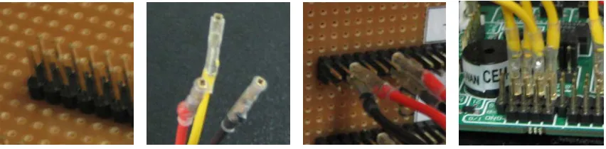
[image:31.595.134.560.381.486.2]Traditionally the connection of components may have taken place by soldering required connections onto controllers and power supplies or by connecting them together with large plugs. However, this approach has the main disadvantage that it makes it harder to change the configuration of the robot, as if a sensor needs to be moved or removed it needs to be unsoldered or removed from a plug. Another approach which avoids this problem is to use solder-less bread boards to connect components. These work well for rapid prototyping of a circuit, however are not very robust and may become dislodged on a travelling robot.
Figure 3.3 FRP Component connections
To avoid the time consuming process of soldering and the frailty of bread boards, all connections for the components are connected using a pin and socket system. This is advantageous as the connections are easily changed and are sturdy enough to stay connected during robot travel. The OOPic controller has pins for component
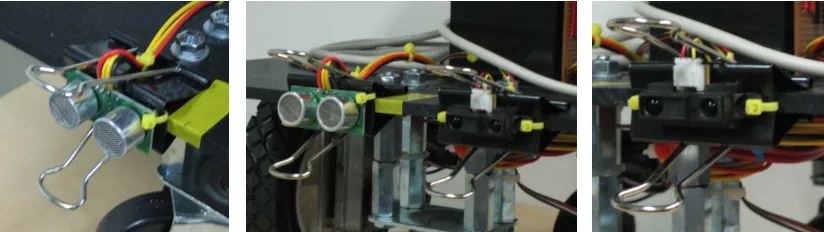
3.2.3.2 Sensor Mounting
Sensor mounting is an important aspect of a robot’s design. The mounting location of a sensor determines the meaning of the sensor’s output for the robot as a whole. For example, a sensor mounted looking forward might detect an object in a robot’s path, whereas a sensor mounted looking to the left may detect objects the robot is passing. Obviously the object detected directly in the robot’s path has much greater
implications to the robot as it will need to take some action to avoid the obstacle. The majority of robot platforms have sensors installed into the robot’s base in an arbitrary manner usually forming some kind of sensor array. This may be suitable most of the time however is limiting should the sensor configuration need to be changed,
[image:32.595.129.541.323.439.2]especially if the mounting is part of the robot’s chassis.
Figure 3.4 Flexible Robot Platform Sensor Mounting
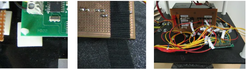
3.2.3.3 Component Mounting
Figure 3.5 Flexible Robot Platform Component Mounting
In order to preserve the flexibility to move components within the platform, the non sensor components have been attached to the robot’s chassis using Velcro™ and printed circuit board (PCB) Standoffs. This allows the components on the FRP to be moved or re-positioned as required. However, the components are also adequately attached to the platform so that they do not fall off during travel.
3.2.4 OOPic API
In order to control the FRP’s sensors and actuators the laptop must communicate with the OOPic Controller within the platform. This is a complex process, so in order to simplify the control of the platform an API for the OOPic microcontroller was created. The API for control provides the FRP with a great deal of flexibility as it allows algorithms for the FRP to be quickly and easily implemented. In addition, a programmer of an algorithm only needs a basic understanding of the functioning of the components being controlled.
3.2.4.1 OOPic Operation
Each of the objects has an associated memory space with object properties which can be read and written to control the device that the object is connected to. In order to access this memory from a laptop the OOPic’s serial control protocol (SCP) is used. The SCP allows parts of memory to be accessed on the OOPic controller and also the ability to transfer data over the OOPic’s I2C Bus, allowing access to any device connected.
3.2.4.2 API Design
The API has been designed to leverage the features provided by the OOPic controller. The API models the memory of OOPic objects and registers of I2C
devices with objects in the API and provides methods to manipulate them. In order to make the API and algorithms using it as fast as possible a local copy of the OOPic memory and I2C object registers are stored in local memory (on the laptop). This means that the OOPic only needs to be accessed to acquire new data or write new command values.
In order to make the API as portable as possible it has been programmed using Java (Java Technology). Java can be run on common operating systems such as Windows, Mac OS and Unix/Linux.
To allow algorithms to be simply created the OOPic API handles all serial
communication with the OOPic via the serial control protocol. This means that users are simply provided with objects from the API which allows easy access to the devices connected to the OOPic. Users simply need to create instances of the
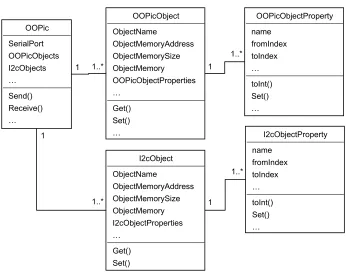
Figure 3.6 Simplified diagram of OOPic API
Figure 3.6 shows the basic structure of the OOPic API. Users simply create an OOPic instance, which is related to a particular serial port, then add either OOPic or I2C objects to the OOPic instance. The object properties are pre-defined and allow the setting of device properties, such as motor speed.
3.2.4.3 Implementation
The implementation of the OOPic API required the use of several procedures and also spurred the development of enhancements to the API.
In order to program the memory locations of device properties into the API a
discovery process had to be used. The memory locations for properties of devices on the OOPic are not all provided in documentation, thus in order to determine the location of the properties in memory a discovery process was used. This involved programming the OOPic to modify a single device property and taking a snapshot of the devices memory before and after the change. The differences in the two
snapshots then allowed the property’s memory locations to be identified.
On examination of the OOPic programming it was discovered that objects are placed in memory in the order that they are created in the program loaded onto the OOPic. From this observation it was possible to create an automated code generator and also automatically determine the memory location of objects on the OOPic within the API. This provides two main advantages to users. Firstly, they do not need to know how to program the OOPic microcontroller, they can simply load on the
automatically generated program. Secondly, they do not need to calculate the location of objects or object properties in the memory of the OOPic controller.
3.2.4.4 Documentation
Documentation is an important aspect of the API as it allows users to quickly and easily learn how to program it. In order to create a comprehensive set of
documentation the automated Java documentation tool JavaDoc was used. This ensured that all aspects of the API were documented and also allowed additional information to be added to the documentation. Another advantage provided by
3.2.5 Flexible Robot Platform
[image:37.595.148.518.229.725.2]The modules, connection mechanisms, and software that have been brought together to form the Flexible Robot Platform (Figure 3.7), result in an easily configured and programmed robot platform. The platform also has ample space and mechanisms to allow the platform to be extended for use in a wide variety of applications. The total cost of the platform not including the laptop was around one thousand dollars.
Chapter 4
Testing and Analysis
In order to comprehensively test the Flexible Robot Platform, a number of tests and comparisons have been performed. This includes a comparison of the FRP with existing commercial platforms. Two quantitative navigational tests and a comparison of the motion capabilities of the FRP to investigate its usefulness in testing non-terrestrial mobile robot algorithms.
4.1 Flexibility Feature Comparison
In order to determine the flexibility of the Flexible Robot Platform its features have been compared against the flexibility factors identified in Figure 3.1 and the
commercial mobile robot platforms introduced in 1.3. This allows a measure of how much flexibility was achieved in the creation of the FRP. The commercial platforms have been used for comparison as their specifications were more readily available and current.
4.1.1 Procedure
To allow a comparison between the platforms it is necessary to define each of flexibility factors, in order to determine whether each particular platform possesses the characteristic. Comparison against a defined set of factors also ensures that bias is not given to a particular platform. The definitions for each factor are defined in Table 2.
Factor/Characteristic Defined As
Ability to carry additional processing A laptop or small form factor PC can be added to its configuration.
Ability to interface third party components Has available digital and analogue I/O lines, which can be accessed using its API
Laboratory or work bench operation Can be operated within a laboratory or on a work bench Large Payload Capacity Can carry a maximum payload of over 10kg
Low Cost Total cost of the working platform is under two thousand dollars.
Re-configurable chassis Configuration of chassis can be changed without modification of the platform’s original design
Re-positionable sensors Sensors on the platform can be easily moved to new positions on the chassis
Well developed and documented API
[image:38.595.122.546.512.702.2]API provides access to all platforms features and is documented well enough to create new algorithms without extra help
4.1.2 Results
The results for the comparison are displayed in Table 3. If a platform fulfilled the definition for a factor it has been marked capable. Also, if a platform partially filled the definition it has been marked as limited. For platforms which require a laptop to complete the platform an additional one thousand dollars (the price of a low cost laptop) has been added to the platform’s cost.
A ct iv M ed ia Ro b o ti cs P io n ee r 1 E v o lu ti o n Ro b o ti cs E R -1 P er so n al Ro b o t S y st em K -T ea m K h ep er a II L eg o M in d st o rm s N o m ad S u p er S co u t II M ic ro Ro b o t “A li ce ” F le x ib le Ro b o t P la tf o rm
Ability to carry additional
processing ■ ■ ■ ■
Ability to interface third party
components □ ■ □ □ ■
Laboratory or work bench
operation ■ ■ ■ ■ ■ ■ ■
Large payload capacity ■ □ ■ ■
Low cost ■ ■ ■ ■
Re-configurable Chassis ■ ■
Re-positionable sensors ■ ■ ■
Well developed and documented
API ■ □ ■ ■ ■ ■ ■
[image:39.595.133.535.223.512.2]■ Capable □Limited
Table 3 Terrestrial mobile robots and their flexibility characteristics
4.1.3 Analysis
4.2 Straight Line Test
In order to perform quantitative testing of the Flexible Robot Platform a series of three straight line navigation experiments developed and performed by Ibeanusi and others (1999) were performed using the Flexible Robot Platform. Ibeanusi and others performed the experiments using a Pioneer 1 mobile robot and have published their results, allowing a comparison of the performance between the Pioneer 1 and the FRP in this basic navigational task. However, the experiments also allow a test of the flexibility of the FRP as the FRP must adopt a sensor configuration and control algorithm to match that of the Pioneer 1 mobile robot. As the FRP is adopting a matching configuration it is expected that the FRP will perform similarly to the Pioneer 1 platform.
4.2.1 Procedure
The three experiments involve programming a mobile robot platform to travel in a straight line for 4877mm (16ft) using three different navigation methods. The first experiment (A) involves using a ‘move’ function to simply move the robot the specified distance. The second experiment (B) sets the robot’s wheels to a common speed and monitors the cumulative distance travelled. The third experiment (C) steers the robot left or right depending on sonar information.
The Pioneer 1 robot is programmed using Saphira software in a C like language. However, this software is specific to the Pioneer robot platform and could not be used with the FRP. In order to implement the experiments a set of methods were created as an additional layer to the OOPic API developed for the FRP. The methods perform the following actions and their code can be found on the CD in Appendix E.
setSpeed()
settings are stored in a lookup table, so that when a speed is selected the closest matching register setting can be selected and set.
readSonar()
This method operates the sonar sensor on the FRP and then returns a distance in millimetres. The distance is based on the amount of time taken for the sonar ‘ping’ to be echoed back to the sensor. If no echo is received then the function returns a distance of 0.
updatePosition()
This method reads the incremental change in wheel rotation from the FRP encoders and then calculates the position of the FRP using the well known equations for odometry (Klarer 1988, pp. 16-8), a convenient rewrite of these equations is also provided by (Borenstein, J, Everett & Feng 1996, p. 20).
move()
This method uses the updatePosition() and setSpeed() methods and attempts to steer the FRP in a straight line for the specified distance at the specified speed.
The creation of these methods allows the experiment programs to be written in a manner similar to that of the programs written by Ibeanusi and others. Before performing the experiments, the FRP was calibrated by instructing the platform to move 2 meters with the move() command. The actual distance travelled was recorded over 5 runs and averaged (a), then divided by the distance (d) and multiplied by the wheel diameter (Wda) to produce a new calibrated wheel diameter (Wdb) (See
Equation 1).
a
b Wd
d a
Wd
=
Equation 1 FRP calibration
Figure 4.1 Straight line experiment pseudo-code
4.2.1.1 Experiment A
Experiment A utilizes the move() method created as an additional layer to the FRP OOPic API for the straight line tests. It should be noted that although this algorithm is assumed to be similar to the code in Saphira software used by the Pioneer 1, this could not be confirmed as the code was not available for comparison.
4.2.1.2 Experiment B
Experiment B sets both wheels of the FRP to 200mm/s and then actively alters the speed of each motor to maintain this speed as closely as possible. It is assumed that the Pioneer 1 Saphira Software also functions in a similar manner. When 4877mm has been reached the wheels are stopped.
Experiment A
move(4877);
Experiment B
while(robot.dist < 4877) { // while robot has not travelled 4877mm
setSpeed(200,200); // set robot speed to 200mm/s
}
setSpeed(0); // set robot speed to 0 (stop)
Experiment C
keep_away = avg(5_sonar_reads);
while (robot.dist < 4877){ // while robot has not travelled 4877mm
avg = avg(last_5_sonar_reads); If (avg < keep_away-50) {
setSpeed(200,230); // slowly turn left
} else if ( avg > keep_away+50){
setSpeed(230,200); // slowly turn right
}else {
setSpeed(200,200); }
}
4.2.1.3 Experiment C
Experiment C sets both wheels of the FRP to 200mm/s and then, depending on the sonar sensor, moves one wheel faster at 230mm/s if the robot is 50mm further away or 50mm too close to the wall with respect to the computed keep_away value (See Figure 4.1). To implement this experiment on the FRP, two changes from the implementation by Ibeanusi and others were made. Firstly, Ibeanusi and others implemented a weighted average for the robot sonar readings. However, as the weighting system used is unknown a weighted average was not used in the FRP implementation. Secondly, rotation of the robot if it exceeds 50mm from the
keep_away value is facilitated by setting the speed of one of the wheels to 230mm/s, which may have resulted in a change in rotation slightly more than 2 degrees per second as implemented by Ibeanusi and others.
1. Robot aligned at start point 508mm from wall 2. Experiment program run
3. Experiment run to completion or stopped if robot collided with wall 4. Distance from start point recorded
5. Distance from wall recorded
Figure 4.2 Straight line experiment procedure
Each experiment was run 24 times, using the procedure in Figure 4.2. The
experiments were performed against a straight length of wall 5 meters in length and on a dense carpet surface. For convenience the starting position for the robot was marked on the floor using electrical tape and positioned at this point at the start of each test. The centre line of the platform was also marked for measurement purposes. Figure 4.3 shows how the experiment area was setup.
common point of measure, however, it will have an affect on experiment C, where the wall is used for sonar measurement by the robot platform. This factor is discussed in more detail in section 4.2.3.
Figure 4.3 Experiment area setup
4.2.2 Results Run 1
The data recorded from running each of the experiments is located in Appendix A. For each of the straight line experiments run, the mean, standard deviation and t statistics were computed as in the paper by Ibeanusi and others (1999, p. 3), using equations 2, 3 and 4.
∑
= = ′ n i i x n x 1 1Equation 2 Mean distance
1 ) ( 2 − ′ − =
∑
n x x s iEquation 3 Standard deviation
n s x t / µ − ′ =
Equation 4 Students t statistic
The mean provides an indication of how far the robot is travelling in each of the
three experiments. The standard deviation shows the amount of spread between each
of the travel values and the mean. The t statistic provides an indication of how well
the sampling distribution represents the real distribution for each experiment with
respect to the target travel for both X and Y. According to Ibeanusi and others (1999)
a t statistic value between -3.0 and +3.0 can be attributed to chance, whereas a value
out of this range indicates that some kind of systematic error is occurring in the
robot’s control.
The following results have Y travel values adjusted for comparison with the Pioneer
1 platform, however the recorded data for each of the experiments is included in
Appendix A.
Experiment A Experiment B Experiment C
Statistics
in mm X Travel Y Travel X Travel Y Travel X Travel Y Travel
Target µ 4877 508 4877 508 4877 508
Mean Travel
x’ 4742.8 395.9 4848 399 4843 535
Standard
Deviation s 10.45 78.39 8 82 16.5 241
Student’s t
[image:45.595.124.545.279.406.2]Statistic t -65.64 -7.03 -17.76 -6.51 -10.09 0.55
Table 4 Straight line test statistics with Pioneer 1 (Ibeanusi et al 1999)
Experiment A Experiment B Experiment C
Statistics
in mm X Travel Y Travel X Travel Y Travel X Travel Y Travel
Target µ 4877 508 4877 508 4877 508
Mean
Travel x’ 5193.25 354.2917 4812.458 465.5 4303.667 558.0833
Standard
Deviation s 786.2355 307.7146 179.4164 256.9688 57.35827 102.7212
Student’s t
Statistic t 1.970532 -2.44712 -1.76232 -0.81024 -55.8215 2.63042 Table 5 Straight line test statistics with FRP run 1
The statistical values for each of the experiments calculated for both X and Y travel
using the FRP are presented in Table 5 and the values for the Pioneer 1 platform
experiments as performed by Ibeanusi and others (1999) in Table 4. On examination
of the mean and t statistic values for the FRP it appears that very little systematic
error is occurring. However, the standard deviation values for the experiment are far
greater than would be expected, especially when compared with the results obtained
by Ibeanusi and others (1999, pp. 4-5) using a Pioneer 1 robot platform. As the FRP
errors, there is indication of an error in a part of the FRP implementation. The
problem is clearly shown in Figure 4.4.
0 200 400 600 800 1000 1200 1400
0 1000 2000 3000 4000 5000 6000
Y Travel mm
X Travel mm Experiment A,B,C - Run 1 Flexible Robot Platform vs. Pioneer 1
Optimal Path Flexible Robot Platform Pioneer 1 0 200 400 600 800 1000 1200 1400
0 1000 2000 3000 4000 5000 6000
Y Travel mm
X Travel mm Experiment A - Run 2 Flexible Robot Platform vs. Pioneer 1
[image:46.595.129.541.141.372.2]Optimal Path Flexible Robot Platform Pioneer 1
Figure 4.4 Straight line test, experiments A, B & C
The indication of an error by the results prompted an analysis of the FRP code to
determine what might be causing the poor results of the FRP. The analysis of code
exposed a problem in the code which retrieves encoder data. The code was using a
process of pause-read-clear-play to obtain encoder readings from an encoder register
on the OOPic microcontroller. However, as the wheels would continue to turn whilst
performing this process, the rotational information generated during the reading
process was being lost. The algorithm was fixed by modifying the algorithm to only
read the encoder register and determine the amount of rotation from the difference
compared to the last encoder read. This ensures that no encoder information is lost.
Subsequent to fixing the error in the algorithm for the experiments, each of the
experiments were re-run in order to produce a more accurate comparison between the
4.2.3 Results Run 2
Before running the experiments for the second time the FRP platform was
re-calibrated as the previous calibration would have been inaccurate for the platform
with the new encoder reading method. The FRP was calibrated again using Equation
1, however this time a distance of 4 meters was used 10 times in order to produce a
more accurate calibration.
Experiment A Experiment B Experiment C
Statistics
in mm X Travel Y Travel X Travel Y Travel X Travel Y Travel
Target µ 4877 508 4877 508 4877 508
Mean Travel
x’ 4952.458 569.0833 4951.792 548.25 4970.542 533.5833
Standard
Deviation s 5.897525 30.63376 7.002976 115.7472 10.20221 48.11121
Student’s t
[image:47.595.121.546.232.364.2]Statistic t 62.68203 9.768502 52.32102 1.703574 44.91758 2.605053 Table 6 Straight line test statistics with FRP run 2
The data recorded for the second run of the straight line test can also be found in
Appendix A. The statistics generated from the results gathered for the second run of
the straight line test on the FRP (Table 6) are greatly improved compared to the first
run and, as was originally expected, are similar to the statistical results (Table 4)
from Ibeanusi and others (1999) with the Pioneer 1 platform. In all of the
experiments the FRP moves further than the target distance of 4877mm with a small
amount of deviation. This would indicate that there is some kind of systematic error
such as an inaccuracy in the FRP calibration or controlling program causing it to
travel further than intended. The Y travel statistics for the experiments however are
0 200 400 600 800 1000 1200 1400
0 1000 2000 3000 4000 5000 6000
Y Travel mm
X Travel mm Experiment A - Run 2 Flexible Robot Platform vs. Pioneer 1
Optimal Path Flexible Robot Platform Pioneer 1 0 200 400 600 800 1000 1200 1400
0 1000 2000 3000 4000 5000 6000
Y Travel mm
X Travel mm Experiment B - Run 2 Flexible Robot Platform vs. Pioneer 1
[image:48.595.132.541.80.308.2]Optimal Path Flexible Robot Platform Pioneer 1
Figure 4.5 Straight Line Test: Experiment A Run 2
Experiment A shows that the FRP manages to more consistently move in a straight
line than the Pioneer 1 platform, achieving a tighter clustering of end points. This is
reflected by the FRP’s Y travel standard deviation of 30.63 as opposed to 78.39
achieved by the Pioneer 1. However, the FRP appears to veer consistently to the left
and, as observed by Ibeanusi and others, (1999, p. 4) the Pioneer 1 platform appears
to drift to the right (towards the wall). The more consistent results achieved by the
FRP may be the result of two main factors. Firstly, the control algorithm may be
superior to that of the Pioneer 1 in this circumstance. The second and more likely
reason for the improvement is the difference in encoder resolution of each of the
platforms. The Pioneer 1 having a resolution of 100 ticks per revolution (Pioneer
Mobile Robots: Operation Manual 1998) and the FRP 500 ticks per revolution,
providing the FRP with greater resolution and thus the ability to more accurately
0 200 400 600 800 1000 1200 1400
0 1000 2000 3000 4000 5000 6000
Y Travel mm
X Travel mm Experiment B - Run 2 Flexible Robot Platform vs. Pioneer 1
Optimal Path Flexible Robot Platform Pioneer 1 0 200 400 600 800 1000 1200 1400
0 1000 2000 3000 4000 5000 6000
Y Travel mm
X Travel mm Experiment C - Run 2 Flexible Robot Platform vs. Pioneer 1
[image:49.595.133.541.81.308.2]Optimal Path Flexible Robot Platform Pioneer 1
Figure 4.6 Straight Line Test: Experiment B Run 2
Experiment B produced similar results for both platforms. The FRP has a higher
standard deviation for Y travel. However, on examination of the graphed results in
Figure 4.6 this would appear to be due to a noisy result. The veering of the robot
platforms to the right or left appears to be occurring as in experiment A to a lesser
extent. 0 200 400 600 800 1000 1200 1400
0 1000 2000 3000 4000 5000 6000
Y Travel mm
X Travel mm Experiment C - Run 2 Flexible Robot Platform vs. Pioneer 1
[image:49.595.131.542.475.695.2]Optimal Path Flexible Robot Platform Pioneer 1
Although the results for the second run of experiment C indicate that the FRP
performs better for Y travel, the results are inconclusive due to a number of factors
relating to the use of sonar. Firstly, the platforms were situated at different distances
from the wall, the FRP being placed further away as the platform was placed 508mm
form the wall rather than its centre line. This should reduce the performance of the
FRP, however, as the accuracy of sonar sensors decreases with distance due to their
cone shaped sensitivity (Nehmzow 2003, p. 29). The second factor affecting the
experiment is the use of different sonar sensors on the FRP and Pioneer 1 platform.
The FRP uses a SRF04 sonar sensor which has a range of 3cm to 3m where as the
Pioneer 1 has a Polaroid type sensor which has a range of 15cm to 5m. This provides
the FRP with a higher resolution over the shorter distance. In addition the FRP may
be sampling its sonar sensor at a higher rate resulting in a more current reading of the
distance to the wall and a faster response to correct Y travel error.
4.2.4 Analysis
The second run of the experiments with the FRP show that the platform can perform
as well as, if not better than, the Pioneer 1 platform. The FRP achieved a lower
standard deviation than the Pioneer 1 platform on all measurements except the Y
travel in experiment B. Also, the test shows that the FRP platform has been
successful in its non performance based objectives. The FRP has been able to
successfully perform an experiment designed for another mobile robot platform (the
Pioneer 1). In addition, the FRP allowed the identification of an error in the
platform’s control algorithm through running the experiments. This is significant as
the initial algorithm was thought to be correct and so the FRP has been an important
4.3 UMBmark test
In order to provide further quantitative measures of the Flexible Robot Platform the
UMBmark (University of Michigan Benchmark test) test developed by Borenstein
and others at the University of Michigan (1995) was run using the Flexible Robot
Platform. The test provides a measure of the odometric accuracy of a platform for
systematic errors.
4.3.1 Procedure
The UMBmark test involves running the robot platform along a pre-programmed
4x4m square path in both the clockwise and counter clockwise direction (see Figure
4.9). The robot is run in a clockwise (CW) and counter clockwise (CCW) direction to
eliminate the problem where odometry errors are concealed due to the fact they
compensate for each other (Borenstein, Johann & Feng 1995, p. 5). Running the
robot in the CCW direction should identify these errors. The position of the robot is
measured against a reference wall both before and after the robot has performed the
square path and compared to the position calculated by the robot’s internal odometry.
In order to run the experiment using the FRP the methods created for the straight line
tests (section 4.2) were used with the addition of a new method which turns the FRP
1. At the beginning of the run, measure the absolute position of the vehicle and initialize to that position the starting point of the vehicle’s odometry.
2. Run the vehicle through a 4x4m square path in CW direction ensuring to:
- Stop after each 4m leg
- Make a total of four 90° turns on the spot - Run the vehicle slowly to avoid slippage 3. Upon returning to start area, measure the
absolute position of the vehicle.
4. Compare the absolute position to the robot’s calculated position, based on odometry using Equation 5.
5. Repeat steps 1-4 for four more times (i.e., a total of five runs).
6. Repeat steps 1-5 in the CCW direction. 7. Use equations 6, 7 and 8 to express the
experimental results quantitatively as the measure of odometric accuracy for systematic
[image:52.595.126.394.80.334.2]errorsEmax.syst.
[image:52.595.352.559.84.316.2]Figure 4.8 Summary of the UMBmark procedure (adapted from (Borenstein, Johann & Feng 1995, p. 7))
Figure 4.9 UMBmark square path and associated error (adapted from (Borenstein,
Johann & Feng 1995, p. 5))
Once the experiment has been run 5 times in both directions (10 runs total) the
UMBmark score can be determined for the robot platform using the following
equations created by Borenstein and others (1995).
For each of the runs a set of return position errors can be computed from the
calculated and absolute positions.
calc abs x
x
x= −
∈
calc abs y
y
y= −
∈
where y x∈
∈ , - Position errors due to odometry
abs abs y
x , - Absolute position of the robot
calc calc y
x , - Position of the robot computed form odometry
Equation 5 UMBmark: Return position error
From the return position errors (Equation 5) two ‘centres of gravity’ (average of the
runs in each direction) can be computed. Computing the ‘centres of gravity’ reduces
the effect of non-systematic errors (Borenstein, Johann & Feng 1995, p. 5).
Start
Reference Wall
Programmed Path CW Absolute Path CCW Absolute Path