/
Switch-Mode Blind Equalizers
for
Single-User Systems
Wee Gin Lim
B.Eng.(Hons)
(University College
London)
December
2003
A THESIS SUBMITTED FOR THE DEGREE OF DOCTOR OF PHILOSOPHY OF THE AUSTRALIAN NATIONAL UNIVERSITY
THE AUSTRALIAN NATIONAL UNIVERSITY
Department
of
Telecommunications
Engineering
1
Declaration
The contents of this thesis are the results of original research and have not been submitted for a higher degree to any other university or institution.
Much of the work in this thesis has been accepted or has been submitted for / publication as journal papers, conference papers or patents. These papers are:
• W. G. Lim, T. D. Abhayapala, and R. A. Kennedy, "Reliability based soft transition between blind startup and decision directed algorithms," submitted
to IEEE Trans. Commun. for publication in Oct 2003.
• W. G. Lim, R. A. Kennedy, and T. D. Abhayapala, "Fast-convergence deci-sion feedback equalizer under parallel adaptation," submitted to IEEE Trans.
Commun. for publication in Dec 2003.
Papers accepted and submitted in Conference Proceedings, but in some cases con-taining material overlapping with the above are:
• W. G. Lim, T. D. Abhayapala, and R. A. Kennedy, "Reliability based soft transition technique for dual-mode blind equalizers," submitted to IEEE In-ternational Conference on Communications, Paris, 2004, for publication. • W. G. Lim, "Torque based rotational study of several blind equalization
al-gorithms for QAM signals," Accepted to Australian Communications Theory Workshop (AusCTW), Newcastle, Australia, Feb 2004.
Patent disclosures connected with research contract work for News Technology, Los Angeles, CA and Philips Research USA, Briarchiff Manor, NY:
• W. G. Lim, R. A. Kennedy, and T. D. Abhayapala, "Parallel adaptation strategy for robust and rapid convergence to the decision directed mode in a blind adaptive decision feedback equalizer," Jun 2001.
• W. G. Li1n, "Tri mode equalizer (TRIME) for time varying channels," Jun 2001.
.. 11
Wee Gin Lim
Department of Telecom1nunications
Research School of Infonnation Sciences and Engineering The Australian National University
111
Acknowledgements
The work presented in this thesis would not have been possible without the support of a number of individuals and organizations, and they are gratefully acknowledged below:
• My supervisors Prof Rod Kennedy and Dr Thushara Abhayapala who guided and nurtured me throughout my years of PhD in Australia and eventually, producing this thesis. I am considered very blessed to be able to work under these two very distinguished and outstanding researchers both in my field of adaptive equalization and several other emerging fields.
• )VIy fellow students in the Department of Telecommunication Engineering, for their friendships. Nis Lesley Cox, administrator of the Department of Telecommunication Engineering, for simply being the very best administrator I have ever known. Ms Rita Murray, business manager of the Research School of Information Sciences and Engineering, for all her kind assistance in making my stay in Australia a pleasant, memorable and problem-free one.
• The Australian National University Malaysian Alumni body for providing me with the PhD scholarship.
• The industrial collaboration with News Technology, Los Angeles, CA and Philips Research USA, Briarchiff Nianor, NY, that gave me the opportunity to be involved in designs for real-life practical telecommunication syste111s. • My parents and brother for all their heart-felt love, unceasing encouragement,
V
Abstract
This thesis considers the design of equalizers which need to operate in various modes ( two or more modes) depending on the difficulty of the channel and the performance of the equalizer. We consider the formulation of such switch-mode equalizers where it is usually broken into an acquisition mode and a tracking mode. As a broad goal, our objectives include speeding up the convergence rate of blind adaptive algorithms which are well-known for their slow rate of convergence, achieving low steady state errors as well as reducing switching transients during the switch-over between operation modes.
A novel concept based on the reliability of the equalizer output is developed and presented where unlike conventional algorithms which utilize only explicit in-formation regarding the equalizer output, the reliability measure is calculated as a function of both the equalizer output and its estimated statistical distribution. Two separate algorithms are developed based on this concept. The first is a switch-mode algorithm that uses the reliability measure to combine the acquisition algo-rithm and the tracking algorithm to achieve not only a smooth transition between 1nodes, but also increased rate of convergence and lower steady state errors. While the first algorithm that co1nputes the reliability measure requires an estimate of the variance of the residual intersymbol-interference (ISI) and noise term, the sec-ond algorithm uses a simple technique of combining that computes the probability of the equalizer output being close to the constellation data points instead. The second algorithm extends and si1n plifies the first algorithm and is shown to achieve fast convergence, low steady state errors and s1nooth transition at a significantly lower computational cost.
Vl
DFE's to accomplish the robust tracking of tirne-varying channel statistics and to retain low steady state errors simultaneously by a novel interplay of the equalizer structure and the transfer of equalizer tap para1neters between the filter blocks.
Contents
Declaration
Acknowledgements
List of Figures
List of Tables
1 Introduction
1.1 Overview of Thesis 1.2 Contributions . . .
2 Background on Single-User Blind Equalizers 2.1 Model of a Digital Communications System .
2.1.1 Digitally Modulated Source Signals . .
2.1.2 Inter-Symbol Interference and Eye Diagram 2.1.3 Perfonnance Measures
2.2 Equalizer Structures . . .
2.3
2. 2 .1 Linear transversal equalizers 2.2.2 Non-linear equalizers . . . . Criteria That Lead To ISI Cancellation 2.3.1 Zero Forcing Algorithm . . . . .
2.3.2 Least Mean Squared (LMS) Algorithm 2.3.3 Unsupervised (Blind) Algorithms
2.4 Overview of Non-Bussgang Techniques . 2.4.1 Historical Notes . . . .
2.4.2 Classifications of Blind Deconvolution Algorithms 2.4.3 Polyspectra algorithms . . . . 2.4.4 Algorithms based on cyclostationary statistics 2.4.5 Probabilistic algorithms . . . .
Vlll Contents
2.5
Bussgang Algorithms .28
2.5.1
Maximurn-Level-Error (MLE) algorithm29
2.5.2
Sato algorithn131
2.5.3
Godard algorithm .34
2.5.4
Shalvi and Weinstein algorithm36
2.5.5
Multi-Modulus Algorithm37
2.5.6
Bussgang algorithms for multiple-modulus constellation .39
2.5.7
Decision directed algorithms40
2.6
Principal Ai1ns Of Thesis .41
3 Reliability Based Technique For Switch-Mode Blind Algorithms 43
3.1
Motivation .44
3.2
System Model46
3.2.1
Expressions for error function of switch-1node algorithms47
3.3
Review of traditional switch-mode algorithms49
3.3.1
Benveniste-Goursat (BG) algorithm .49
3.3.2
Stop-And-Go (SAG) decision directed algorithm49
3.3.3
Dual-Mode Generalized Sato Algorithm (DMGSA) andDual-Mode Godard Algorithm (DMGA)
50
3.3.4
Hilal- Duhamel (HD) algorithm51
3.3.5
Diagra1ns of error functions52
3.4
A Novel Reliability Based Switch-Mode Algorithm .54
3.4.1
Co1nputation of Reliability Measurea(k)
55
3.5
Discussions on convergence and approximation .59
3.5.1
Convergence .59
3.5.2
Gaussian assu1nption of effective noise61
3.6
Simulation Results63
3.7
Conclusions66
4 Probabilistic-Based Switching Technique For Switch-Mode
Algo-rithms 67
4.1
Problem Statement . . .68
4.2
Graphical Illu tration of Switching Difficulty in Switch-ModeAlgo-rith111s . . . .
4.2.1
Non-Constant ::Aodulus Constellation4.2.2
Constant Modulus Constellation . . .69
Contents lX
5
6
4.4.1
System Model . . .75
4.4.2
Development of Novel Tri-Mode Algorithm . . ·76
4.4.3
Performance Improvements via Pre-Whitening80
4.5
Simulation Results . . .81
4.5.1
Results for Stationary Channel Without Phase Errors .84
4.6
4.5.2
Results for Joint Equalization and Phase Recovery Conclusions . . . .Fast Convergence Switch-Mode DFE Schemes
5.1
Introduction .5.1.1
Channel Decomposition Property5.2
Design Objectives .5.2.1
System Model .5.3
Development of Alternative Fast-Convergence DFE5.4
Parallel Adaptation Strategy for Dual Mode Equalization Schemes .5.5
Alternative Fast-Convergence Predictive DFE Scheme .5.5.1
Switching Strategy5.6
Novel Dual Decision Feedback Equalizer5.6.1
Problem Statement5.6.2
Development5.6.3
Operation Details5.7
Simulation Results5.7.1
Switch-Mode Conventional DFE Scheme of Section5.3
-Channel Equalization Results5.7.2
Switch-Mode Conventional DFE Scheme of Section5.3
-Channel Identification Results .5.7.3
Switch-Mode Conventional DFE Scheme Under ParallelAdap-tation Strategy
5.7.4
New Switch-Mode DFE Sche1nes of Sections5.3
,
5.4
and5.5
- Channel Equalization Results5.7.5
Switch-Mode Dual DFE Scheme of Section5.6
-
Channel Equalization Results5.8
ConclusionsRotational Analysis On Several Blind Equalization Algorithms
6.1
Introduction .6.2
System Setup and Assumptions6.3
Torque Analysis of Undesirable Rotated SolutionsX
7
6.4
6
.
3.1
Some Wrong Rotated Solutions . . . .6.3.2
Preli1ninaries on Torque Concepts and So1ne Definitions .6.3.3
Rotational Behavior of the CMA . . . .6.3.4
Rotational Behaviors of RCA and MMA ConclusionsConclusions
7.1
Executive Summary .7.2
Future Work .7.2.1
Direct Extensions7.2.2
GeneralizationsContents
124
125
126
127
130
133
133
134
134
135
Appendix A Computation of mean of absolute value of error
func-tions,
E{
IE(k) I}
137List of Figures
2.1 _A typical conununication syste1n. . . 8 2.2 Constellation diagran1 of modulation fonnats for (A) 16-QAM, (B)
4-PA_!I, (C) 8-PSK, (D) 16-APK (V29-CCITT). . . 9 2.3 (-A) Linear noisy baseband equivalent channel 1nodel. (B)
Discrete-ti1ne channel i1npulse response obtained fro1n the continuous-ti1ne
response . . . . 10
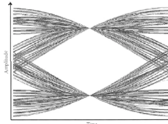
2.4 Eye diagra1n. 12
2.5 Linear Transversal Filter. . 14
2.6 Conventional decision feedback equalizer. 16
2. 7 Predictive decision feedback equalizer. 17
2.8 Linear Transversal Bussgang Equalizer. 29
2. 9 _ !Iaxi1nu1n Level Error (MLE) Algorithn1: Constellation diagra1n for 16-QAJ\11 ,N"ith dotted-line boundary connecting the edge data points.
The equalizer is only updated if the output is exceeds the boundary
depicted by the dotted lines. . . 30 2.10 Reduced Constellation _Algorith1n (RC_A): Constellation diagra1n for
16-QA_ !I and its reduced constellation ·whose 4 data points are
rep-re ented by 'o' at coordinates [ s, , sJ, Virhere "Ys is defined in (2.44). 33 2.11 Godard algorithm or Constant Modulus Algorith1n ( C1\!I_A): It
penal-izes deviation fro1n a constant 111odulus represented by the dotted circle for (-A) -PSK which is a constant 1nodulus source, and (B)
16-QA111 Virhich is a non-constant 1nodulus source. . . 34 2.12 1\!Iulti 1\!Iodulus Algorith1n (1\111\!I_A): It penalizes deviations from 1
11
for real and co1nplex components eparately. . . 38 2.13 1\111\!I_A2 and the DA1\!I_A algorith1n The 9 radii of the 64-QAJ\11
con tellation. 40
3 .1 _A_ typical ba eband equivalent channel and a linear equalizer that
xii List of Figures
3.2 The error functions of the switch-mode algorithms outlined in the above subsections for 8-PAM signalling. Their shapes vary with the equalizer output z(k) only. (A) Benveniste-Goursat (BG) algo-rith1n [15], with para1neters k1 = 1, k2 = 0.25. (B) Stop-And-Go
(SAG) algorithm [116]. (C) Dual-Mode Generalized Sato Algorithm (DMGSA) [145], with the decision region
D
(k)
=di±
0.5,vi,
where { di} is the set of the source constellation. (D) Dual-Mode GodardAlgorith1n (DMGA) [145] with the decision region
D
(k) =di±
0.5,vi.
53 3.3 Contour plots of the reliability measure of (3.29) for a 4-PAM data. 56 3.4 Relationship between the DD MSE and <Yv for M-ary PAM withM = 2, 4, · · · , 64. The range of values of <Yv is from 0.1 to 1.4
presented in the log scale. . . 58 3.5 The error function of the novel switch-mode algorithm of Equation
(3.21). Here , = 14. . . 60 3.6 Cross sections of the 3-D graph of the error function of the new
dual-1node algorithm for 8-PAM signalling and , = 100. (A) <Yv = 1.2
and (B) a-v = 0. 7. The error functions of the CMA and the LMS
algorithms are also plotted as dashed and dotted lines respectively. 61 3.7 A co1nparison of several dual-mode algorith1ns equalizing channels
(A) h', and (B) h", both at an SNR of 25dB for 4-PAM signalling. . 63 3.8 A co1nparison of several dual-mode algorithms equalizing channels
H1(z) with an SNR of (A) 20 dB, and (B) 15 dB for 4-PAM signalling. 64 3.9 Similar to Fig. 3.7, this graph also includes the new equalizer that
is prefixed ,vith a recursive whitening filter where lower steady state MSE is achieved due to the additional whitening filter which in-crease the effective length of the equalizer, thereby being able to estimate the channel more accurately. The S R is 25 dB, and a
4-P A:t\1 ource is used. . . 65 4.1 The plots of jE(k)I for (A) CMA-1, (B) C)VIA-2, (C) DD algorith1n
(D) DA~VIA algorith1n, for the non-constant rnodulus 16-QAM source ignal . . . . . 4.2 The plot of jE(k)I for (A) DD algorithm, (B) DAMA algorithm, for
the con tant 1nodulu 8-PSK source ignals. The plots of lc(k)I for C~v1A-1 and C~1A-2 are identical to Fig. 4.1-A,B, except that
,25)
70
List of Figures
4.3 The new switch-mode algorithm featuring adaptation with the
ac-quisition algorithm when z(k) is outside the individual square
re-Xlll
gions surrounding each data point, and with the tracking algorithm
otherwise. . . 72 4.4 Baseband QAM system model for joint blind equalization and phase
recovery . . . .
4.5 The new tri-mode blind equalization algorithm. The reliable re-gions
D(k)
=
UDp(k),p=
1, 2, · · · , 32 andDout(k)
where the DDalgorithm and the MMA are respectively employed for the 32-QAM constellation are illustrated. The CMA is employed outside these
regions.
75
78 4.6 Figures illustrating the technique for joint equalization and phase
recovery for 16-QAM signals in the presence of phase errors. The
emphasis is on the variable-size reliable region,
D
( k).
. .
. .
. . . .
79 4. 7 Comparing various algorithms using the channel h' under SNRlev-els of 15dB and 25dB only. The modulation format is 16-QAM.
Equalizer has 31 taps. 84
4.8 Comparing various algorithms using the channel h" under SNR level
of 15dB. The modulation format is 16-QAM. Equalizer has 41 taps. 86 4.9 Comparing various algorithms using the channel h111
under SNR level
of 17dB. The modulation format is 16-QAM. Equalizer has 41 taps. 87 4.10 Comparing various algorithms using the channel h' under SNR levels
of 25dB and 30dB. The modulation fonnat is 32-QAM. . . 88 4.11 Comparing various algorithms using the channels h"' under SNR
level of 30dB. The modulation format is 32-QAM. . . 89 4.12 Comparing various algorithms in different equalizer setups. 92
5.1 Decomposition of a transversal non-minimum phase channel via the channel decomposition property with H(z)
= 9Hmin
(z)
H
ap(z),
as-suming the complex gain,
9
,
is unity. . . 94 5.2 Novel blind linear equalizer setup [75] as a cascade of four devicesused to acquire the "decomposed" channel. . . 95 5.3 Linear equalizer of acquisition 1node of the alternative DFE scheme
x1 v List of Figures
5.5 New DFE scheme under parallel adaptation. The taps are adapted and shared among filters from "top" and "bottom" paths of the new
DFE. . . 101 5.6 The new alternative fast-convergence predictive DFE. . . 103 5.7 The dual DFE scheme which features a conventional DFE that is
prefixed by a linear recursive filter whose taps are driven by a pre-dictive DFE which is not in the equalizer path (illustrated by the dotted lines) but it minimizes the residual error at the soft output
of the conventional D FE, y (
k).
. .
.
. . .
.
. . .
.
. . .
. . . .
. .
.
106 5.8 (A) and (B) are comparisons of three DFE schemes for the firstchannel, h', while ( C) and (D) are for the second channel, h", using 16-QAM data signals. The first equalizer is the DFE of [75]. The second and third equalizers are the DFE described in Section 5.3 without and with parallel adaptation strategy, respectively. The parallel adaptation strategy ernploys the Benveniste-Goursat type
combination parameters. . . 110 5.9 The 100 n1ost dominant taps of the inverse response of channel h'". 112 5.10 Channel identification results using new switch-mode DFE scheme
proposed in Section 5.3. These results are obtained using (A) 300 symbols, (B) 800 symbols, (C) 2500 symbols. The equalizer is in its acquisition n1ode for both (A) and (B). As for ( C), the equalizer has settled into its tracking (DD) mode . . . .
5.11 The average MSE and SER of 20 runs of fast convergence DFE scheme of Section 5.3, with (solid line) and without ( dotted line) parallel adaptation strategy on 8-PAM signals at 30 dB for channel
113
h'". . . .. . . 114 5.12 Results of two new alternative DFE's compared with trained
equal-izers. . . 115 5.13 Plot of the equalizer output of various selected schemes extracted at
the end of the data stream. (A) CMA equalizer. (B) Trained LMS equalizer. (C) Fast converging blind predictive DFE. (D) Our FIR sche111e and the trained DFE, which yields similar MSE.
5.14 Coin paring three equalizers: 1) the linear acquisition equalizer (LE) of [75], 2) the DFE sche111e of [75] and 3) the dual-DFE that extends
116
the DFE in [75]. . . 118
List of Figures
6.2 Examples of undesirable rotated solutions for (A) 16-QAM at 21 °, obtained by RCA and CMA; (B) 32-QAM at 45°, obtained by RCA
xv
and CMA; ( C) 16-QAM under a frequency offset, obtained by CMA. 124 6.3 Rotational behavior of RCA for square-QAM constellations. The
non-flat region in Fig. (B) indicates that there is an undesirable but rotationally stable equilibriu1n point which is at the vicinity of 21 °. This is also reflected in Fig. ( C) where a shallow local minimum is
observed for av ~ 0 and 68(k) ~ 21° . . . 127 6.4 Rotational behavior of RCA for cross-QAM constellations. The large
non-flat regions in Figures (B) and (E) at the vicinity of 45° indicate that the RCA is very susceptible to the '45°' wrong solutions. This is also reflected in the cost figures ( C), (F) where a local 1ninimum point clearly exists at 45°. There are two 1nore stable points for 32-QAlv1 as shown in Figure (B) at high S TR and around 13° and
21° .. . . . . . . 128 6.5 Rotational behavior of MMA for 16-QA1v1 constellation. Identica
l-shaped figures are observed for 32-, 64- and 128-QAM, so they are not plotted. Figure (B) shoy\ s no signs of a negative mean torque and this is true also for 32-, 64- and 128-QA_ II. This phenomenon is also reflected in the cos function V\ hich does not have any undesirable
local 1ninimum. . . . .
A_. l The probability densitJ functions (p.d.f.) of the error functions of the I\ OE C_ !IA, and the L !IS algorithms. The solid lines represent
130
the c.d.f. for
a
;
=
0.28 and the dotted lines fora
;
=
0.69. . . 138 A.2 The cu1nulati -e distribution functions ( c.d.f.) of the error functionsof the I\!IOE CI\!I_A and the LI\!IS algorithms. The solid lines repre-sent the c.d.f. for
a
;
=
0.28 and the dotted lines fora
;
=
0.69. TheList of Tables
3.1 Lookup table for MSEDD(o-v) and variance of effective noise, o-~ for
M-PAM signals . . . 59 3.2 Summary of results in Fig. 3.7 including failure rates 66
4.1 Characteristics of blind algorithms
4.2 Progressive stages in new algorithm and associated step sizes
em-ployed in our simulations in the presence of phase errors
..
XVll
77
Chapter
1
Introduction
This thesis deals with switch-111ode blind equalizers for single-user digital communi-cation systems. A switch-mode equalizer is a co111bination of two or 111ore equalizer
modes where it usually starts with a linear equalizer that e111ploys an acquisition algorithm and later switches over to a tracking decision directed algorith111 after the data esti111ates have beco111e sufficiently reliable. In terms of the filtering struc-ture, a non-linear decision feedback equalizer may be used in the tracking 111ode. In the acquisition mode, the equalizer is designed to be robust with respect to the channel's initial conditions but 111ay yield high steady state errors even when its convergence is achieved. The tracking equalizer, on the other hand, yields lower steady state errors at convergence but cannot be used reliably to acquire severe channels ( which do not correspond to initial open-eye conditions [92, 99]). There-fore, sv1itch-111ode blind equalizers have become very popular in practical digital communication syste111s because the distinct advantages of the acquisition and tracking modes are complementary.
In this introductory chapter, we present an overview of the contents of the thesis and provide a list of the contributions. It features several novel swit ch-mode algorith111s as v. ell as switch-mode equalization sche111es. Other contributions
relating to the global topic of switch-mode equalization are also presented.
1.1
Overview of Thesis
Chapter 2 - In this background chapter we give a brief overview of the do111ain of digital transmission as well as reception over linear channels. The
prob-lem of intersy111bol interference (ISI) is presented and the notion of equaliza-tion is defined. Equalizer structures including linear transversal equalizers,
2 Introduction
presented. Subsequently, a concise overview of blind equalization techniques
is given, the emphasis being on Bussgang-type algorith1ns. Non-Bussgang algorith1ns such as the polyspectra algorithms, the cyclostationary-statistics
algorithms and the probabilistic algorithms are also briefly described. Lastly, we present an analysis of the undesirable solutions ( due to the non-convexity
of cost functions) of the most widely used algorithms such as the Sato and
Godard algorith1ns.
Chapter 3 - This chapter addresses the problems induced by abruptly switching
between acquisition and tracking algorithms. We use a novel reliability
mea-sure to combine the two algorithms to provide a soft transition and avoid
having to accurately determine the open-eye threshold for the tracking
al-gorithm to be reliably employed. We derive the reliability measure fro1n
Bayes theorem and compute the posterior probability of correctly detecting
the equalizer output. From the derivation we find that in order to
effec-tively provide a soft transition between algorithms, not only the equalizer
output needs to be utilized, but the statistical distribution of the residual
intersymbol-interference (ISI) plus noise term is also required. Once the reli-ability measure is accurately esti1nated, it leads to significant i1nprovements over conventional algorithms such as the Benveniste-Goursat algorithm
[15]
as well as the Stop-And-Go algorithm[116].
Chapter 4 - This chapter further considers the problem of smooth switching be-tween acquisition and tracking algorithms. In the same spirit as the reliability-based algorithm proposed in Chapter 3, we design an alternative switch-mode algorith1n that also utilizes information regarding the equalizer output and its estimated distribution to ensure a s1nooth transition between algorith1ns. This new algorith1n is based on a simple concept that employs the track-ing algorith1n when the equalizer output is found in reliable regions in the constellation space. Otherwise, an acquisition algorithm is e1nployed. The novelty lies in the way the size of these reliability regions is varied accord-ing to a new probabilistic measure regarding the reliability of the equalizer output.
In addition, this chapter also presents an algorithm capable of joint blind equalization and phase recovery by using the new switch-mode technique.
Chap-1.2 Contributions 3
ters 3 and 4. Overall, this chapter addresses the speed of convergence and
improved robustness while retaining the simplicity of an equalization scheme
proposed by Labat, Macchi and Laot [75]. We first address the problem of
the undesirable use of a recursive linear filter structure in the acquisition
mode by proposing a new transversal filter while preserving the ability of
direct transfer of the taps to the D FE in the tracking mode. Secondly, we
address the problem of eliminating switching transients of dual-mode
equaliz-ers during the switch-over between acquisition and tracking modes where the
positions of several filter blocks need to be rearranged. We propose a novel
strategy that combines the acquisition linear equalizer and the tracking DFE
in a parallel fashion to reduce the switching transients effectively. Lastly, the
chapter addresses the problem of tracking time-varying channels with a new
dual-DFE equalization scheme that features two DFE in an equalizer setup
and involves a novel interplay of the equalizer structures and the transfer of
filter coefficients between the filter blocks.
Chapter 6 - We analyze the phase and/or frequency locking (rotational) conver-gence behavior of several blind algorithms, namely the CMA, the reduced
constellation algorithm (RCA) and the multi-modulus algorithm (MMA)1.
The principle objective is to assess their susceptibilities to wrong solutions
( stable undesirable equiibria) which correspond to an output constellation
that is a undesirable rotated version of the original data constellation. In
our analysis, we define a "torque" that is the cross product of the equalizer
output and the "force" which is due to the error function acting on the
equal-izer output symbol. A net torque will correspond to a rotational behavior
of the equalizer output in either the clockwise direction or the anti-clockwise
direction.
Chapter 7 - Son1e concluding remarks and future work are presented in this chap -ter.
1.2
Contributions
At this point, a list of major contributions of this thesis is given:
• New treatment of switching for enhanced equalizer performance
-1
The MMA we consider in this Chapter is proposed by Oh and Chin [105], and Yang et
al [152]. It should not be confused with another algorithm previously proposed by Sethares et
4 Introduction
Smooth switching algorithms are designed to avoid the difficult task of having to accurately determine an open-eye condition so that the tracking algorithm may be employed reliably. The major contribution drawn from Chapters 3 and 4 is in the design of superior smooth s101itching switch-mode algorithms. While
conventional techniques usually tradeoff convergence speed and steady state per-fonnance for smoothness in the switch-over, our techniques actually accelerate convergence in addition to ensuring smooth transitions between modes.
• Dual-parameter measure for estimating reliability of the equalizer out-put
-The reliability-based switch-mode algorithm offers effective smooth-switching that enhances convergence rate and preserves low steady state errors based on a concept that utilizes explicit and implicit information in the equalizer output signals. In contrast to conventional smooth switching algorithms that employ a single-parameter2 measure for combining the switch-mode algorith1n, our new dual-parameter reliability measure as proposed in Chapter 3 results in not only a s1nooth transition between the acquisition and tracking algorithms, but also in
a faster, more reliable convergence as well as lower steady state errors. • Simple algorithm for rapid acquisition
-The new measure for combining the switch-mode algorithm as proposed in Cha
p-ter 4 is designed to be simple and effective in ensuring a smooth switching be
-tween algorith1ns. While conventional algorithms usually trade off equalizer per
-fonnance, e.g., convergence speed and steady state errors, with computational complexity, this algorith1n is shown to outperform several well-known switch-mode algorithms at a reduced cost. This is because the novel measure can be
used to accurately reflect an open-eye condition without having to collect many
data sa1nples. The switch-over therefore occurs promptly as soon as the data esti1nates beco1ne sufficiently reliable.
• Joint blind equalization and automatic phase recovery
-By coupling the si1nple switching technique described above and the results in Chapter 6 regarding phase recovery properties of the MMA, a new switch-mode
algorithm is propo ed to achieve joint blind ·equalization and phase recovery effectively. The phase offsets can be corrected by the MMA and the frequency off ets can be handled through the use of the smooth switching technique of
Chapter 4. 2
Conventional single-para1neter measures rely solely on either the equalizer output, e.g., [15],
1.2 Contributions 5
• New fast convergence switch-mode decision feedback equalization (DFE)
scheme
-We extended a fast convergence equalization scheme proposed by Labat, Macchi and Laot in 1998 to incorporate a simple linear transversal acquisition equalizer which can be switched to a DFE when the error rate is sufficiently low. Deficien-cies inherent in the recursive filtering structure in [75] can be overcome with this modification. After a transformation in the transversal filter, the direct trans-fer of the taps from the acquisition equalizer to the tracking equalizer ( which involves a recursive feedback filter) is also retained.
• Soft transition strategy for new switch-mode DFE scheme
-A parallel adaptation strategy that combines the linear equalizer and the tracking DFE in a parallel fashion can reduce the switching transients that are due to the rearrangement of the filter blocks as well as a switch in the adaptation algorithms. We showed significant improvement in terms of smooth switching between the linear equalizer and the DFE as well as rate of convergence with this strategy, even when a simple Benveniste-Goursat combination technique is used.
• Dual DFE scheme for tracking varying channels
-The dual-DFE, unlike conventional equalizers which usually implement just a single DFE, may exhibit enhanced tracking capabilities in non-stationary envi-ronments and low steady state MSE in stationary environments. The complexity incurred which is less than twice of that of a single DFE is reasonable for its achieved improvements.
• Rotational analysis of blind equalization algorithms
Chapter
2
Background on Single-User Blind
Equalizers
For bandwidth-efficient communication syste111s operating in high inter-symbol in-terference (ISI) environments, adaptive equalizers have become a necessary
compo-nent of the receiver architecture. An accurate estimate of the amplitude and phase
distortion introduced by the channel is essential to achieve high data rates with
low error probabilities. An adaptive equalizer provides a simple practical device that is capable of both learning and inverting the distorting effects of the channel. Conventional equalizers rely on the transmission of a training sequence known to both the transmitter and receiver. The blind equalizer, on the other hand, does
not require a training sequence to be sent for start-up or restart. Rather, the
blind equalization algorithms exploit a priori knowledge regarding the statistics of the transmitted data sequence as opposed to an exact set of symbols known to the transceiver, thereby achieving improved bandwidth utilization. Blind equaliza-tion is also desirable when the communication system must cope with multipoint broadcast environments and unpredictable channel changes [147].
In this chapter, a concise background on the communications systems is pro-vided. We recommend the following references [12, 38, 58, 117- 119, 141] for an excellent tutorial overview of the field. Our focus will be to provide sufficient self
-contained background on the subjects which the thesis deals with predominantly,
i.e., a variety of equalizer structures and popular blind algorithms.
2.1
Model of a Digital Communications System
Throughout this thesis we will be dealing with aspects related to the physical layer
of a communications system, 1.e., the transmission layer. A typical communica
8 Background on Single-User Blind Equalizers
Other Sources
Information Source Channel Multiplex Modulate Tx Source Encode Encode
Tx Medium (Channel)
Information Source Channel Demultiplex Demodulate Rx Sink Decode Decode
Other Sources
Figure 2.1: A typical com1nunication system.
tions system is illustrated in Fig. 2.1. The complete cycle of the transmit-receive process begins with the original infonnation being formatted in a digital form in order to be represented by a series of bits. These digits are then source-encoded whereby the message is represented in a succinct form and the redundancy is be-ing removed as much as possible. The resulting sequence is then channel-encoded where redundancy is now introduced into the data stream in a deliberate but con-trolled manner for the purpose of detecting and possibly correcting the errors due to transmission. This is also known as error control coding. One technique of
error control coding is to introduce frequent symbol changes so that the symbol clock speed can be easily recovered in the receiver. Also, often a number of bits
are encoded into one or more symbols. At this point, multiplexing with sequences fro1n other sources 1nay be perfonned to efficiently. utilize the limited bandwidth of co1nmunication channels. Finally, the sequence is converted by the modulator into continuous-ti1ne passband wavefonns, in accordance with modulation schemes
that are suitable for trans1nission over the channel. Examples of communications
channel include coaxial, fiber optic, or twisted-pair cables in wired communications;
and the atmosphere or ocean in wireless co1nmunications, or some combination of
these 1nedia. This resulting wavefonn is then delivered to the receiver at the other
end of the channel.
At the receiver, the processes prior to transmission need to be "inverted" in
order to recover the original trans1nitted information. The received waveform is first demodulated and de1nultiplexed. Subsequently, the sequence is equalized and
decoded in order to give the final digital output. Equalization is necessary to combat the impainnents of the channel that 1nay have caused signal distortions.
2.1.1
Digital
l
y
Modulated
Source
Signal
s
The infonnation bearing bits are usually collected in blocks of say K consecutive
2.1 Model of a Digital Communications System 9
would correspond to a symbol. The set of all possible symbols is called the
al-phabet set A of the transmitted symbols of a particular modulation fonnat. Each
of these possible symbols is then mapped to one of 2K different continuous-time
lowpass waveforms by attributing to the set of symbols a discrete set of amplitudes,
frequencies and/ or phases, depending on the modulation format of the specific sys-tem. For example, let we consider Quadrature Amplitude Modulation (QAM) and
let there be K
=
4 binary digits in each block. Thus, there are 24=
16 differentsequences as follows:
[0000, 0001, 0010, 0011, · · · , 1110, 1111]. (2.1)
The QAM alphabet set can be represented by the set of sequences in (2.1) where each sequence is uniquely mapped to one of 16 different constellation points in the complex plane as in Fig. 2.2. The resulting 16-QAM alphabet set is thus
A= {±1 ±
j,±1 ±
3j,±3 ±
j,±3 ± 3j}.
(2.2)*
*
*
*
*
*
*
*
*
*
*
*
*
*
*
*
(A) (B)
*
*
*
*
*
*
* *
*
*
*
*
(C) (D)
[image:28.790.162.661.566.1023.2]10 Background on Single-User Blind Equalizers
For other 1nodulation formats such as the Pulse A1nplitude Modulation (PAM)
and the Phase Shift Keying (PSK) formats, they differ from the QAM example by only the mapping operator that maps each of the sequence in 2.1 to one of
the alphabet in 2.2. The constellation points of 16-QAM; 4-PAM, 8-PSK, and the 16-APK (A1nplitude-Phase Keying, also widely known as 16 point V29-CCITT for 9,600 bits per second modems). The choice of modulation formats usually trades off between bandwidth efficiency and probability of error, where larger constellations
1nay utilize the bandwidth more efficiently but suffers higher probability of error.
More recently, some new techniques that vary the 1nodulation constellation size
according to the time-varying channel conditions in order to 1naintain a specified target reliability in the receiver output have been proposed [52, 61].
2.1.2
Inter-Symbol
Interference and Eye Diagram
In a nutshell, inter-symbol interference (ISI) in a digital transmission system is the distortion of the received signal that is manifested in the te1nporal spreading. The overlap of individual pulses and their adjacent pulses would usually result in the receiver being unable to reliably distinguish between individual signal elements.
Linear
channel
h(t)
(A)
Noise n(t)
(B)
h(t)
Figure 2.3: (A) Linear noisy baseband equivalent channel model.
(
B
)
Discrete-time channel i1npulse response obtained from the continuous-time response.Consider a linear ti1ne invariant (LTI) baseband equivalent channel1 whose im-pulse respon e
h(t)
is shown in Fig. 2.3. Then the received signalr(t)
is obtained by convolving the input ignala(t)
with the channel's impulse responseh(t)
,
givingr(t)
= a(t)
@
h(t)
+
n(t)
=
L
ajh(t -
jT)+
n(t)
J
(2.3a) (2.3b)
1 In this 1nodel
1 the channel includes the effects of the transmitter filter, the modulator, the
[image:29.804.143.658.588.789.2]2.1 Model of a Digital Communications System 11
where 0 denotes convolution, T seconds is the signalling interval and n(
t)
is the additive white Gaussian noise (AWGN). When the continuous-time signal issam-pled at kT
+
t
0 , wheret
0 accounts for the channel delay and sampler phase, the sampled signal becomesr(t
0+
kT)=
akh(t
0 )+
~ajh(to
+
kT - jT)+
n(to
+
kT)j=/=k
=
akh(to)
+
v(to
+
kT).(2.4a)
(2.4b)
The first term on the right hand side (RHS) of (2.4a) is the desired term scaled by h(t0 ) since it can be used to identify the transmitted signal level. The middle and
last terms on the RHS of (2.4a) are the ISI and AWGN respectively. The sum of ISI
and noise is also known as the effective noise and is denoted by v ( k) 6 v (
t
0+
kT).In the frequency domain, the received signal may be represented by the following
multiplicative process
R(J)
=
A(f)H(f)
(2.5)
where
H(f)
is the Fourier transform of h(t):H(f)
=
'.I(h(t))
=
1:
h(t)e-j21rftdt,(2.6)
and
R(J)
,
A(J)
are similarly defined as3='(r(t))
and3='(a(t)),
respectively. Asuf-ficient condition for zero ISI is for the folded spectrum to have a flat magnitude at all frequencies for
If
I
<
1/2T and a linear phase. This is also known as the Nyquist criterion. Most chann_els that are considered in the thesis are ISI channelswhich linearly distort the transmit signals and the aim objective of equalization is to combat such distortions.
The presence of ISI and noise can be easily visualized using the eye diagram shown in Fig. 2.4. The figure is generated assuming an ideal raised cosine filter was
used with no added noise. The sampling should be carried out at a time offset that corresponds to the two well defined points in the middle where the eye opening
is the largest in the vertical direction. Therefore, when and if the eye is open, the symbol can be accurately detected at the receiver by a simple decision device
with an appropriate timing. When the signal-to-noise-ratio (SNR) drops due to
the addition of the AWGN and/or ISI, then the eye will begin to close, resulting
12 Background on Single-User Blind Equalizers
Figure 2.4: Eye diagram.
2.1.3
Performance
Measures
The ultimate aim of the receiver is to produce a sequence of data estimates with a minimu1n probability of error. When such a measure is difficult to esti1nate or impractical, there are other si1npler performance indices that are closely related to the bit-error-rate. Three commonly used indices are:
1. The closed eye 1neasure ( CLEM)
(
2.7
)
where the sequence with element si is the combined channel-equalizer
re-sponse. It is the ratio of the noise margin level to the total signal level. A small value of the CLE_ /I indicates that the channel eye is sufficiently "open'; .
Usually, if the CLEM is less than unity, then the decision directed algorithm can be reliably e1nployed and the convergence to undesirable local equilibria can be avoided [92], [57, Ch.
3).
2. The ISI measure
(
2.8
)
2.2 Equalizer Structures 13
3. Decision directed 1nean squared error (DD-MSE)
MSE
0o(k)
=
E{
lz(k)
~
Q(z(k))l2}
(2.9)where Q(z(k)) is the nearest neighbor quantization operator appended to the equalizer output
z(k).
A small value of lVISEDD(k) indicates the raw( unquantized) equalizer output is close to a sy1nbol value.
Other 1neasures that can be used include the Kolgomorov-Smirnov as well as the Chi-Squared goodness-of-fit tests, with a suitably chosen null hypothesis, to detennine if the distribution of the equalizer output corresponds to an open eye condition. An example is found in [8].
Among the three above mentioned perfonnance indices, only the MSEDD (
k)
can be practically used under blind equalization because it does not require knowledge of both the unavailable channel and transmitted sequence. The CLEM and ISI measure can be used for theoretical analysis but not for practical real-time digital communication systems.2.2
Equalizer Structures
We now describe several equalizer structures which can be used to mitigate the effects of ISL The choice of the equalizer structure will largely determine the speed of recovery of the linearly distorted data sequence ( convergence of the equalizer) and the error probability of the equalizer output. A linear transversal equalizer can be used to invert the channel and hence recover the trans1nitted input data. Non-linear equalizers such as the maxi1num-likelihood sequence esti1nator and the decision feedback equalizer exploit the discrete nature of the input sy1nbols to cancel ISI and noise in a more effective manner.
2.2.1
Linear transversal equalizers
14 Background on Single-User Blind Equalizers
r(k + !VI) r(k - !VI+ 1) r ( k - ~NI)
z(k) z(k)
Q(·)
Figure 2.5: Linear Transversal Filter.
according to
M
z(k)
=
L
cir(k -i)
(2.10)i=-M
where {
ci
}
are the (2M+
1) tap weight coefficients of the equalizer. Linear equali z-ers designed on the basis of the baud-rate sampled received signal are quite sensitive to symbol timing errors. Therefore, fractionally spaced linear equalizers are widelyused to mitigate the equalizer's sensitivity to symbol timing errors. A fractionally
spaced equalizer (FSE) in the linear transversal structure has the output
M
z(k)
=
L
cf
r
(k -
i) (2.11)i=-M
where
cf
andr
(
i)
are colu1nn vectors with 1nore than one sample per symbolaccording to the oversampling factor, while {
c
i
}
are the (2M+
1) vector tap weightcoefficients of the FSE. The linear equalizers can also be i1nplemented as a lattice filter [118] which is known for its i1nproved convergence and numerical properties.
2.2.2
Non-linear equalizers
In digital com1nunications, the actual goal of equalization is to recover the input
·which is discrete and not to invert the channel. Hence despite the channel being
linear the equalizer needs not be linear. In fact, by most criteria the best equalizer
structures should be non-linear.
Linear equalizers generally do not perform satisfactorily when the channel is severely distorted especially when it has deep spectral nulls in the passband. Non-linear equalizers can deal with such channels more effectively. In the reahn of
non-linear equalizers, two well known approaches are:
Se-2.2 Equalizer Structures 15
shadri [125] that it is possible to perform joint data and channel estimation using the Viterbi algorithm [44]. However, unlike conventional maximum likelihood sequence estimators (MLSE) where the Viterbi algorithm operates on only one trellis, for joint data and channel estimation, the VA operates on many trellises where each of them corresponds to a hypothesized estimate of the channel. The number of trellises grows exponentially with the length of the channel impulse response. The MLSE operates based on the following concept:
The MLSE estimates the information sequence to rnaximize the joint proba-bility of the received sequence conditioned on the information sequence. The
linear FIR channel output is
L
r(k)
=
L
hia(k -
i)+
n(k)
(2.12)i=O
where L
+
l is the channel length and n ( k) is the channel noise. Since n ( k)is often white Gaussian, the ML estimate of the channel input
a(k)
based on a sequence of channel outputr(k)
can be obtained if the channel impulse response is known or has been estimated. This is done by maximizing the likelihood function, or equivalently, by minimizingoo L 2
L
r(k)
-
L
hia(k -
i) (2.13)k=L i=O
If the size of the symbol alphabet is M , then there are ML different possi-ble states or transmitted sequences. The principle of ML receivers is then to choose, among these ML sequences the most likely one to have produced the received sequence { r( k)}. Finding the most likely sequence involves ex-haustive calculation of all the ML metrics, which can be quite complex if the number of states ML is large. A substantially lower computational com -plexity can be achieved by employing the Viterbi algorithm. Reduced state Viterbi algorithms that provide good compromises between complexity and performance by assuming some past decisions are correct have been proposed for channels with long but small tails [37].
16
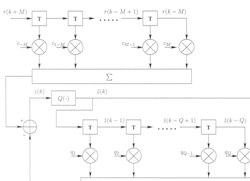
Background on Single-User Blind EqualizersDecision Feedback Equalizer The philosophy of a decision feedback equalizer
(DFE) is to e1nploy previously detected symbols to reduce the impact of ISI
and noise due to those symbols that have distorted the current symbol. The nonlinearity that arises from the use of a decision device significantly i1nproves the performance of the DFE because it exploits the discrete properties of the transmitted sequence. However j it suffers from the error propagation
phe-nomenon whenever a decision error is made [39; 71]. This phenomenon is due
to incorrect decisions traversing the feedback delay line; resulting in enhanced
probability of error until the states have been flushed out completely.
In this thesis; we deal with two types of DFE extensively in Chapter 5. These DFE;s have been commonly used in the literature and are briefly described below:
Conventional Decision Feedback Equalizer
r(k + ~if) r(k - M + 1) r(k - NI)
T
f f
z(k) z(k) Q(·)
z(k - 1) z(k - Q + 1) z(k - Q)
T T
Figure 2.6: Conventional deci ion feedback equalizer.
The DFE \\-a fir t developed b Au tin [7]. It wa intended to combat the I I due to channel \\-ith evere amplitude di tortion ) u ing deci ion feedback to
cancel the interference from y1nbol \\-hich have already been detected. It i imple -mented a a ca cade of a for\\-ard filter and a feedback filter that i equipped with
[image:35.813.144.655.501.870.2]2.2 Equalizer Structures 17
given by
M Q
z(k)
=
L
cir(k - i) -L
qjfi(k -j)
(2.14)i=-M j=l
where qj is the tap weight coefficient of the feedback filter with length Q, and
a(
k) is the output of the decision device. The forward filter is similar to the linear equalizer that 111ay be symbol-rate or fractionally spaced. The feedback filter however musthave tap spacing that equals the symbol interval.
Predictive Decision Feedback Equalizer
r(k + NJ) r(k - ]VJ+ 1) r(k - M)
T
s(k)
z(k) z(k)
Q(,)
z(k - 1 z(k - P + 1) z(k - P)
T T
Figure 2.7: Predictive decision feedback equalizer.
A nonlinear equalizer, shown in Fig. 2. 7, that is equivalent to the conventional
DFE under the condition that the forward filter has an infinite number of taps was proposed by Belfiore and Park
[10]
.
It is known as the predictive DFE andis developed as follows. Given the MMSE forward filter, say an infinite-length FSE, then the sequence of sy111bol-rate signals at the output of this forward filter
forms a set of sufficient statistics for estimating the transmitting sequence. Thus by
[image:36.790.162.677.415.816.2]18 Background on Single-User Blind Equalizers
device that eliminates the contribution of ISI and noise to the equalized signal. The output of the MMSE forward filter is given in the usual form of (2.11). The predictive DFE output, which is the input to the decision device, is given by
M p
z(k)
=
L
cir(k - i) -L
Pj{
s(k -j
) -
ci(k -j)}
(2.15)i=-M j=l
where pj is the tap weight coefficient of the predictive feedback filter with length
P, and s(k) is the output of the forward filter.
Remarks on conventional DFE and predictive DFE :
1. Both conventional DFE and predictive DFE have identical expressions of min-imum achievable MSE when the lengths of the forward filters of the equalizers are unconstrained, even when the feedback filter is reduced to a finite length. The output of the infinite length linear predictor is a white noise sequence with corresponding minimum MSE that is identical to that of the conven-tional DFE. A proof of their equivalence can be found in [119], [118].
2. In contrast to the conventional DFE whose forward filter depends on the number of feedback coefficients, the forward filter of the predictive DFE is independent of the predictor coefficients. Optimizations of the forward filter and the feedback predictor in the predictive DFE can be done separately. Hence, its MSE is at least as large as that of the conventional DFE. In spite of this sub-optimality of the predictive DFE, it is more suited for trellis-coded signals than the conventional DFE [40 143].
3. Usually the conventional DFE and the predictive DFE are not used simul-taneously because they are essentially equivalent [10]. However, we found a new way to incorporate both DFE's in Chapter 5.6 to enhance the tracking capability of the equalizer in time-varying channels.
2.3
Criteri
a That Lead To ISI Cancellation
2.3 Criteria That Lead To ISI Cancellation 19
without a known training sequence. Consequently other criteria in the spirit of
lowering the error probability have been proposed. We will review two criteria in
this section, namely the peak distortion criterion and the mean-square-error
crite-rion. The former is used to invert the channel directly while the latter minimizes
the error between the raw equalizer output data with its quantized output. In
digital communications where the input is discrete, the latter criterion is usually
preferred.
2.3.1
Zero Forcing Algorithm
The zero forcing (ZF) equalizer minimizes the so-called peak distortion criterion
[118], which is in essence the residual ISI (without the AWGN term) given by
CX)
]zF
=
L
ls(k) I (2.16a)k=-oo,k-/=-0
CX) CX)
L L
Cj ( k) h ( k -j)
(2.16b)k=-oo,k-/=-0 j=-00
where { s ( k)} is the combined channel-equalizer impulse response, i.e., the
convolu-tion of the channel impulse response, {
Cj},
and the equalizer coefficients, { hj}. TheZF cost is the peak value of the interference term minus the term corresponding
to the (k
= O)th
tap and the noise term, divided bys(O)
which is often nonnalizedto be unity. With an infinitely long equalizer, JzF can be zeroed. Effectively, this
corresponds to the complete elimination of ISI. The values of the taps are chosen to
yield non-zero overall channel-equalizer response at decision time, i.e., k
=
0, andzero elsewhere. In other words this corresponds to choosing equalizer coefficients
so that the following condition is satisfied:
where
CX)
s(k)
=
·
L
cj(k)h(k -j)
=
5k,o j=-005ko
=
6. { 1, 0
k=O
otherwise
20 Background on Single-User Blind Equalizers
denotes the Kronecker delta. In the z domain, this leads to the direct inversion of the channel ( assuming it is invertible):
1
C(z)
=
H((2
.
18)
where C (
z)
and H (z) denote thez
transform of the { Cj} and { hj}, respectively.Even though the zero-ISI condition generally requires infinite-length symbol-rate ZF equalizers, it can be shown that zero-ISI ZF equalizers of finite length generally exist for fractionally-spaced receivers
[118]
.
Minimizing the peak distortion using a finite length symbol-rate linear equaliz-ers cannot completely eliminate the ISI at the output of the equalizer. However, it can at the least be shown to be a convex function of the equalizer coefficients
[88]
.
A steepest-descent recursive algorithm for adjusting the (2K+
1) equalizer coeffi-cients would there£ ore becj(k
+
1)
=
cj(k)+
µc(k))a*(k -j),
J.=
-K ) · · · ) -1 0 1 ) ) ) · · ·'
K(2.19)
where cj(k) is the value of the jth coefficient at time
t
=
kT, c(k)=
a(k) - z(k)is the error signal at time
t
=
kT and µ is the adaptation step size. When the equalizer coefficients have converged to their global minima, the error is orthogonal to the transmitted sequence, givingE(c(k)a*(k -
j))
=
E[(a(k) - z(k))a*(k -j)J
=
E[a(k)a*(k -j)J -
E[z(k)a*(k -j)J
=
c5j,O -s(j)
=0
J.=
-K ) .. · K )(2.20a)
(2.20b)
(2.20c)
(2.20d)
where we have assumed the transmitted sequence to be i.i.d. and the equalizer output is correct, so that Q(z(k))
=
a(k). The last two lines follow because the opti1nal tap coefficients will give the zero-ISI condition, i.e., s(O)=
1 and s(k)=
0 for 1<
lkl
<
K.2.3.2
Least Mean
Squared (LMS) Algorithm
2.3 Criteria That Lead To ISI Cancellation 21
of the bit-error-rates of the equalizer output. The minimum mean squared error (MMSE) criterion on the other hand ameliorates this problem. Its philosophy is rather than trying to completely eliminate the ISI, the MMSE equalizer minimizes a balanced contribution from the ISI and the channel noise. The instantaneous mean squared value of the error is
E(k)
=
a(k) -z(k)
(2.21)which is the derivative of the MMSE cost function with respective to the equalizer output. Thus, the MMSE cost is
JMMSE
=
E (ia(k) -
z(k)l2)=
E(Ia (
k) - rH ( k) C ( k)n
(2.22)
(2.23)
where
r(k)
is the column vector of the channel output andc(k)
is the column vector of the tap coefficients of the transversal equalizer. The solution to the above criterion is the MMSE equalizer which is given in the z domain by1
C(z)
=
H(z) (2.24)where the additive noise at the channel output is assumed white with power spec-tral density N0 . The minimization of the cost leads to the well known Wiener filter whose ( optimal) tap weights c* are determined by the following Wiener-Hopf equation
(2.25)
where R is the autocorrelation matrix of the equalizer input and p denotes the cross-correlation of the equalizer input and the desired signals [58].
2.3.3
Unsupervised (Blind) Algorithms
The ZF and MMSE equalizers are usually implemented with a training sequence that is known to both the transmitter and the receiver. When the transmission of these sequences is impractical or too costly, an alternative solution is to rely on blind equalization techniques. The Bussgang-type techniques estimate the training signal based only on the received signal and certain a priori statistical information
22 Background on Single-User Blind Equalizers
certain blind algorithms in the literature as this thesis deals primarily with the class of blind algorithms. We first give a brief overview of non-Bussgang techniques before discussing in more detail the class of Bussgang algorithms which is used extensively in this thesis.
2.4
Overview of Non-Bussgang Techniques
2.4.1
Historical Notes
To understand a science it is necessary to know its history.
Auguste Comte (1798- 1857)
The problem of blind deconvolution is the subject of thorough research over the past few decades; under different names and for various applications. The
homomorphic filter was introduced to remove effects of non uniform illumination of images [107, Ch. 10]. An observed image is usually described as a convolution of the object brightness distribution (OBD) by a Point Spread Function (PSF), and blind deconvolution is used to recover the OBD when no reliable information regarding the PSF is available. The name "blind deconvolution" was first used by
Stockham et al for the restoration of old records [132]. Later "minimu1n entropy deconvolution" in seismic data analysis was introduced [149] to find the inverse
of the channel that maximizes the kurtosis of the deconvolved data. The same
concept was later applied to synthetic aperture radar focusing to estimate the rate of change of the Doppler shift of radar echoes [77]. It is also used for image
reconstruction to remove the effects of the blur induced on astronomical plates by short term variations of the refraction index of the atmosphere [154]. At the sa1ne ti1ne, similar concepts were applied to multilevel blind data transmission over
telephone and radio channels.
The search for cost-function-based blind algorithms started with the seminal
work of Sato and Godard [49,124]. Their algorithms were generalized by Benveniste
et al [14] and Sethares et al [126], respectively. Later the Bussgang methods for
blind equalization, which subsume all the algorith1ns in this section, were discovered
by Bellini [11]. Other 1nethods include CMA with 1nultiple radii [120, 126], sign algorithms [144], convex cost functions [68], super exponential methods [127] and the so-called multimodulus-algorithm (MMA) [105, 106, 151, 152]. Alternatively, second order statistics-based algorith1ns that emerged in the early 90's due to Gardner and Tong et al [45,135] have received a lot of attention. Some earlier works