1 INTRODUCTION
A composite sandwich panel made up of glass fibre composite skins and a modified phenolic foam core material for structural applications has been devel-oped in Australia (Van Erp & Roger 2008). The sat-isfactory performance of this sandwich panel in sev-eral building and bridge deck projects has shown the high possibility of using this material for structural beam application. Investigation conducted by Ma-nalo et al. (2010a) showed that this fibre composite sandwich structure has excellent flexural behaviour in the flatwise and in the edgewise positions. How-ever, before this sandwich panel can be used for structural beam application, a thorough understand-ing of its shear behaviour is necessary as the shear strength is an important consideration when design-ing composite sandwich construction.
In a number of sandwich structures, the main design criterion is the shear strength of the core ma-terial. It has been demonstrated that, under service loads, most sandwich constructions failed due to shear failure of the core material (Kampner & Grenestedt 2007). The brittle nature of the core ma-terial causes a sudden collapse of the composite sandwich structure after the formation of the first shear crack. In structural applications, this is more critical as thicker and higher density core material is required for composite sandwich beams to transfer the shear between the top and bottom skins com-pared to other industrial applications (Styles et al. 2007). Hence, the premature failure of the core mate-rial will have an adverse effect on the structural
per-formance of composite sandwich beams and may be the limiting factor in designing such structures. It is essential therefore to eliminate this type of failure to be able to use fibre composite sandwich construction efficiently in structural applications.
In this paper, attempts to improve the structural performance of the composite sandwich structures by making the fibre composite skins carry some of the loads usually carried by the core have been made. No significant material development investi-gation was conducted and existing composite sand-wich structure was used. In order to attain this, the composite sandwich beams were loaded in the trans-verse and in-plane directions. With the introduction of the vertical fibre composite skins on both sides of the core material, it is anticipated that the shear re-sistance of the composite sandwich beams will im-prove as the vertical skins might carry part of the shear load. This innovative concept could lead to-wards the improvement of the structural perform-ance of composite sandwich structures while main-taining the simplicity of the production process. An experimental investigation using asymmetrical beam shear test is therefore conducted to understand the behaviour and failure mechanisms of the fibre com-posite sandwich panel when loaded in the transverse and in-plane directions. Finite element simulations were also performed to verify the shear behaviour of the composite sandwich beams using the effective mechanical properties of its constituent materials.
A comparison of the shear behaviour of a fibre composite sandwich
structure in the transverse and in-plane directions
A.C. Manalo, T. Aravinthan & W. Karunasena
Centre of Excellence in Engineered Fibre Composites (CEEFC), University of Southern Queensland,
Toowoomba, Queensland 4350, Australia
D
B
2 EXPERIMENTAL PROGRAM
2.1 Material properties
The composite sandwich panel used in this study is manufactured by LOC Composites Pty Ltd., Austra-lia. This sandwich panel is made up of glass fibre composite skins co-cured onto the core material us-ing a toughened phenol formaldehyde resin. The fi-bre composite skin is made up of two plies of stitched bi-axial (0o/90o) E-CR glass fibre fabrics and has a total thickness of 1.8 mm. The modified phenolic core material is made primarily from natu-ral plant products with a proprietary formulation by the manufacturer. The composite sandwich panel has a nominal thickness of 20 mm. The mechanical properties of the fibre composite skin and the modi-fied phenolic core material were determined in an earlier study conducted by Manalo et al. (2010a, b) and are listed in Table 1.
Table 1. Properties of skin and core of sandwich panels. Test Property Skin Core Flexure Modulus (MPa)
Peak stress (MPa) Strain at peak (%)
14,284 317 2.29
1,326 14 1.22 Shear Modulus (MPa)
Peak stress (MPa) Strain at peak (%)
2,465 22.82 3.11
528 4.25 0.81
2.2 Test specimen
[image:2.595.330.509.260.383.2]The specimens for shear testing were cut into re-quired dimensions from the sandwich panels sup-plied by the manufacturer. In all tests, the span for maximum shear is held constant at 80 mm. Five rep-licates for each specimen type were prepared and tested with only 3 replicates from each type were provided with strain gauge. The details of the speci-men for shear test are listed in Table 2. In this table, the sandwich beam loaded in the transverse (flat-wise) direction is designated as specimen AS-SW-F while the sandwich beam loaded in the in-plane (edgewise) direction is designated as AS-SW-E.
Table 2. Details of specimen for asymmetrical beam shear test. Specimen Illustration Number of
specimens
B D (mm) (mm)
AS-SW-F 5 50 20
AS-SW-E 5 20 50
2.3 Test set-up and procedure
The shear behaviour of composite sandwich beams was determined following the asymmetrical beam
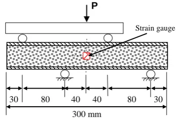
shear test. In this test method, the specimen was eccentrically loaded at two trisected points and the supports were applied at the remaining two points. This loading configuration generates a high shear stress and a nearly zero moment at the centre of the specimen. The test-set-up for the asymmetrical beam shear test is illustrated in Figure 1. The load was ap-plied through a 100 kN servo-hydraulic universal testing machine with a loading rate of 1.3 mm/min. Resistance strain gauges oriented at +45o to the load-ing axis were attached on the surface along the mid-dle line at mid-height of the sandwich beam speci-men to evaluate the shear response during the entire loading regime. The applied load and strains were obtained using a System 5000 data logger. All specimens were tested up to failure to determine the shear strength and the mode of failure.
Figure 1. Illustration of asymmetrical beam shear test.
3 RESULTS AND DISCUSSION
In this section, a comparison between the shear be-haviour of the composite sandwich beams when loaded in the transverse and in-plane directions un-der asymmetrical beam shear test is made.
3.1 Failure load
Table 3 summarises the load at first shear crack of the core and the maximum load carried by the com-posite sandwich beams when loaded in the trans-verse and in-plane directions. For specimen AS-SW-F, the load at first crack is also the maximum load as the specimen failed immediately after the formation of the first shear crack in the core material. A com-parison of the failure load showed a higher load for specimen AS-SW-E than specimen AS-SW-F. Simi-larly, the load when the first crack in the core mate-rial was observed in specimen loaded in-plane is significantly higher than the failure load recorded for specimen loaded in the transverse direction.
Table 3. Failure load of composite sandwich beams. Specimen Load at 1st crack (kN) Failure load
(kN) AS-SW-F 10.52 10.52 AS-SW-E 16.56 17.61
D
B
P
300 mm
30 80 40 40 80 30
[image:2.595.39.288.305.398.2]0 1 2 3 4 5 6
0 2000 4000 6000 8000 10000
Str
e
s
s
(M
Pa
)
Strain (microstrain)
AS-SW-F-1
AS-SW-F-2
AS-SW-F-3
0 5 10 15 20 25 30
0 5000 10000 15000 20000 25000 30000 35000
Str
e
s
s
(MP
a
)
Strain (microstrain)
AS-SW-E-1 AS-SW-E-2 AS-SW-E-3
3.2 Load-strain behaviour
An initial check was conducted to determine if the asymmetrical beam shear test creates a pure shear for composite sandwich structures at the location of maximum shear. If the shear strain is pure, both ten-sile and compressive strains should be equal and op-posite in sign, which can be checked with the strain gauge responses attached to the specimen. Thus, the diagonal tensile (+45o) and compressive (-45o) strain gauge measurements were plotted against the applied load during the entire test regime. The results show that both tensile and compressive strain values from the asymmetrical beam shear test are very close throughout the test, suggesting the presence of a rea-sonably pure field of shear strain at the mid-depth and midspan of the sandwich beam specimen. This result further confirms that the asymmetrical beam shear test is capable of characterizing the shear be-haviour of composite sandwich structures with high strength core material.
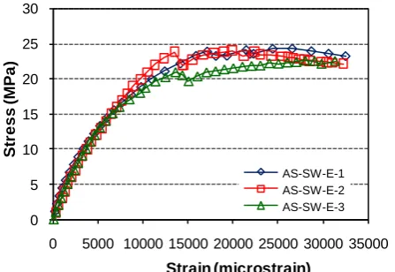
The shear stress-strain relationship of the sand-wich beam specimens provided with strain gauge is shown in Figures 2 and 3. The shear stress of the composite sandwich beam is calculated by dividing the shear force with the transformed area of the composite sandwich section. For specimen AS-SW-F, the cross section of the composite sandwich struc-ture was transformed into an equivalent core mate-rial while the specimen AS-SW-E into an equivalent skin material. This approximation makes the contri-bution of the core and the skin equal because they will have the same properties. This assumption was based on the observed failure mode of sandwich beams under asymmetrical beam shear test which is described in the next section. The shear strain is de-termined from the indicated normal strains of the +45o strain gauges attached to the specimen.
Figure 2 shows that the shear stress of specimen AS-SW-F behaved almost linearly with strain up to failure. As illustrated in the figure, the sandwich beam specimen failed at a shear strain between 7800 and 8400 microstrains. This level of strain is compa-rable to the maximum shear strain recorded in the core material from the coupon tests. However, the slightly higher shear strength of the sandwich beams at failure compared to the shear strength of the core material could be due to the contribution of the fibre composite skins in carrying the shear.
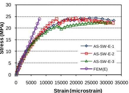
Figure 3 shows that the shear behaviour of speci-men AS-SW-E. The stress-strain curve shows a lin-ear response at a relatively low amount of strain and then started to behave non-linearly with increasing stress until final failure. The non-linearity was am-plified after tensile cracking of the core. Similarly, a slight decrease in shear stress was observed after reaching the ultimate shear capacity. This could be due to the total shear failure of the core material. However, the fibre composite skin is still holding the failed core material. The maximum shear stress
[image:3.595.314.537.146.298.2]re-corded for composite sandwich beam is around 23 MPa with strains of around 30000 microstrains. It is interesting to note that this strength is comparable to the maximum shear strength of the skins established from coupon testing. This also showed that the con-tribution of the vertical skins when loaded in the in-plane direction has a dominant effect on the shear behaviour of composite sandwich beam.
Figure 2. Shear stress-strain behaviour of specimen AS-SW-F.
Figure 3. Shear stress-strain behaviour of specimen AS-SW-E.
3.3 Failure behaviour
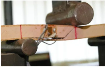
The results of the experiment showed that the com-posite sandwich beams under asymmetrical beam shear test failed in a brittle manner due to shear fail-ure of the core followed by the successive debonding between the skin and the core when loaded in trans-verse direction (Figure 4). The shear failure of the core material occurred at the location of maximum shear. This lacks of reinforcement through the thick-ness direction of the core material results in rela-tively lower shear strength for specimen AS-SW-F. For all the tested specimens, the composite sandwich beams failed after the formation of first shear crack in the core material. In this position, a diagonal shear crack of approximately 45o propagates through the core at the location of maximum shear. This failure is brittle and sudden which is accompanied by a loud noise after the appearance of the first crack.
[image:3.595.313.537.320.474.2]The presence of the vertical fibre composite skins inhibits the development of cracks in the core mate-rial. When the shear crack in the core was observed, a drop in the shear stiffness was noticed. The vertical skins prevented the crack width from increasing and did not cause failure. Shear cracking of the fibre composite skin was then subsequently observed. With increasing load, the shear failure became obvi-ous due to the scaling of the resin at the fibre com-posite skins. Furthermore, the cracking on the skins were contained within the location of the maximum shear, close to the pure shear region. The different failure behaviour of the composite sandwich beam when loaded in-plane can be explained by the ge-ometry and position of the fibre composite skins. Based on these observations, it can be concluded that the vertical fibre composite skins increase the shear capacity of the sandwich beams by preventing the widening of cracks in the core thereby increasing the ultimate load of the specimens.
Figure 4. Failure behaviour of specimen AS-SW-F.
Figure 5. Failure behaviour of specimen AS-SW-E.
3.4 Effect of width of steel plate on shear behaviour
The shear strength of the composite sandwich beams when the load is applied in-plane is expected to be higher than that of beams loaded in the transverse di-rection. This higher load could result in compression or indentation failure under the load rollers and the supports. In an attempt to minimise the effect of load concentration, the influence of the beam support conditions, specifically, the width of the steel plate to distribute the load at the loading points and sup-ports is investigated. Different width of steel plates (with thickness of 3 mm) were provided under the load rollers and the supports to determine the
mini-mum size of the steel plates that can be used during the test to prevent compression and indentation fail-ure without changing the overall behaviour of the composite sandwich beam. The results of this inves-tigation are summarised in Table 4.
Table 4. Failure load of specimens with different plate widths.
Plate width (mm) Failure load (kN) AS-SW-F AS-SW-E
0 10.78 7.58
10 10.75 9.23 20 10.85 15.89 30 10.63 17.60 40 11.16 17.46 50 10.69 18.51
The results show that for all the sandwich beams loaded in the transverse direction, the failure load under asymmetrical beam shear test is nearly equal for the all the plate widths investigated. All the specimens failed at an applied load of around 11 kN. Within the results of the experiment, the sandwich beams loaded in the in-plane direction obtained a slightly higher failure load for wider steel plates. However, there is no significant increase in the fail-ure load of sandwich beams with plate width of 30, 40 and 50 mm. This suggests that the provision of steel plates on the loading points and the supports improves the load distribution on the specimen.
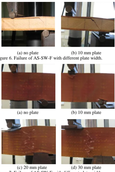
Figure 6 shows the failure mode of sandwich beams loaded in the transverse direction with differ-ent plate widths. Even without steel plates under the loading points and at the supports, there is no any skin indentation failure or local core crushing ob-served on sandwich beams loaded in the transverse directions. This could be due to the presence of the stiffer fibre composite skins throughout the width of the sandwich beam which spreads out the compres-sive stresses under the loading area to the lesser stiff core material preventing any localised failure. All specimens failed due to shear failure of the core ori-ented at approximately 45o to the beam axis, then immediately followed by core-skin debonding.
[image:4.595.61.261.303.435.2]0 1 2 3 4 5 6
0 2000 4000 6000 8000 10000
Str
e
s
s
(M
Pa
)
Strain (microstrain)
AS-SW-F-1
AS-SW-F-2
AS-SW-F-3
FEM(F)
[image:5.595.42.285.32.395.2](a) no plate (b) 10 mm plate Figure 6. Failure of AS-SW-F with different plate width.
(a) no plate (b) 10 mm plate
(c) 20 mm plate (d) 30 mm plate Figure 7. Failure of AS-SW-E with different plate width.
4 FEM SIMULATION AND COMPARISON WITH EXPERIMENTS
Finite element model (FEM) simulations were car-ried out to verify the behaviour of sandwich beams under asymmetrical beam shear test loaded in the transverse and in-plane directions. The results of the numerical simulation and comparison with the ex-perimental results are presented in this section. 4.1 FEM of composite sandwich beam
Simulations of the asymmetrical beam shear test of the composite sandwich beams using Strand7 finite element program have been performed to determine if the behaviour and the ultimate capacity of the composite sandwich beams could be predicted using the material properties established from test of cou-pons. The FEM was carried out simulating the specimen and the loading set-up in the actual ex-perimental conditions to have a reliable result. Due to symmetry, only one-half of the composite sand-wich beams was modelled to reduce the computa-tional time. The skin and the core material were modelled as 20-node hexahedron (Hexa20) brick elements with aspect ratios between 1.1 and 1.4. The number of brick elements and nodes used to develop the FE model for composite sandwich beams under asymmetrical shear test and the computational time are listed in Table 5.
Table 5. Summary of the FEM simulation for sandwich beams. Specimen Hexa20 bricks Nodes CPU time (s) AS-SW-F 13380 62942 1858.3 AS-SW-E 15528 72103 2073.6
4.2 Failure load
Using the maximum strain where the skin and the core materials will fail in shear, the FEM analysis was successful in the prediction of the failure load of the composite sandwich beams tested under asym-metrical beam shear. Based on the FEM model, the shear failure of the core of specimen loaded in the transverse direction occurred at a load of 10 kN while the shear cracking of the core material for sandwich beam loaded in-plane occurred at a load of 15 kN and shear failure of the fibre composite skins occurred at a load of 17 kN. In both directions, fail-ure of the composite sandwich beams occurred at the region of maximum shear.
4.3 Stress-strain behaviour
The shear stress-strain relationship of the composite sandwich beams predicted numerically and the result of the asymmetrical beam shear test are shown in Figures 8 and 9. In these figures, the shear stress-strain behaviour based on FEM when loaded in the transverse and in-plane directions are designated by FEM (F) and FEM (E), respectively. When loaded in the transverse direction, the shear-stress strain be-haviour is almost similar up to failure of the speci-men. When loaded in-plane, a good agreement with the experimental results was observed only at the initial linear portion of the shear stress-strain curve. This could be due to using only the shear modulus value at the linear behaviour of the skins in the FEM simulations while the fibre composite skin behaved non-linearly at higher strain values. Results of the FEM simulations also showed that the slope of shear stress-strain curve for specimen AS-SW-F is equal to the shear modulus of the phenolic core material while that of specimen AS-SW-E to the shear modulus of the fibre composite skin.
[image:5.595.317.538.616.771.2]0 5 10 15 20 25 30
0 5000 10000 15000 20000 25000 30000 35000
Str
e
s
s
(MP
a
)
Strain (microstrain)
AS-SW-E-1
AS-SW-E-2
AS-SW-E-3
FEM(E)
Figure 9. FEM and experimental shear stress-strain behaviour of specimen AS-SW-E.
4.4 Failure behaviour
[image:6.595.50.269.38.197.2]The failure mechanisms of the composite sandwich beams under asymmetrical beam shear test based on the numerical simulations are shown in Figures 10 and 11. The result of the FEM analysis showed a good agreement with the experimental results. In both specimens AS-SW-F and AS-SW-E, the failure mechanisms predicted from the FEM simulations are similar to the failure mechanisms observed in the experimental investigation (Figures 4 and 5). These results further show that using the material proper-ties determined from the coupon tests, the numerical models have provided results in good agreement with the experiment. The FEM simulations also ver-ify that there is no localised failure in sandwich beams even without steel plate for load applied in the transverse direction while a 30 mm plate width minimises the compressive and indentation failure of sandwich beams when the load is applied in-plane.
[image:6.595.71.257.520.625.2]Figure 10. Predicted failure of AS-SW-F at a load of 10 kN.
Figure 11. Predicted failure of AS-SW-E at a load of 17 kN.
5 CONCLUSION
The shear behaviour of a sandwich structure made up of glass fibre composite skins and modified phe-nolic core when loaded in the transverse and in-plane directions was determined using asymmetrical beam shear test. Based on the results of the investi-gations, the following conclusions can be drawn: - The shear behaviour of the composite sandwich
beams loaded in-plane is significantly influenced by the fibre composite skins while the behaviour of the sandwich beams when loaded in the trans-verse direction is governed by the core material.
- The sandwich beam loaded in the transverse di-rection is less prone to indentation and crushing failure due to the presence of the stiffer fibre composite skins to distribute the applied load. - The FEM simulations predicted successfully the
failure load and mechanisms of the beams but showed a good agreement with experiment only at the linear portion of the shear stress-strain curve. - Significant improvement on the shear strength can
be attained when sandwich panels are positioned in-plane. The increase in strength with the intro-duction of the vertical skins suggests the high po-tential of its utilization as a shear loading compo-nent in a structural beam. The presence of vertical skins also leads to more ductile failure behaviour.
6 ACKNOWLEDGEMENT
The authors would like to thank the LOC Compos-ites Pty. Ltd., Australia for providing the composite sandwich panels used in this study.
7 REFERENCES
Kampner, M. & Grenestedt, J.L. 2007. On using corrugated skins to carry shear in sandwich beams. J. Composite Struc-tures 85: 139-148.
Manalo, A.C., Aravinthan, T., Karunasena, W. & Islam, M.M. 2010a. Flexural behaviour of structural composite sandwich beams in flatwise and edgewise positions. J. Composite Structure 92(4): 984-995.
Manalo, A.C., Aravinthan, T., & Karunasena, W. 2010b. In-plane shear behaviour of fibre composite sandwich beams using asymmetrical beam shear test. J. Construction and Building Materials 24(10): 1952-1960.
Styles, M., Compton, P. & Kalyanasundaram, S. 2007. The ef-fect of core thickness on the flexural behaviour of alumin-ium foam sandwich structures. J. Composite Structures 80: 532-538.
Van Erp, G. & Rogers, D. 2008. A highly sustainable fibre composite building panel. Proc. International Workshop on Fibre Composites in Civil Infrastructure – Past, Present and Future, 1-2 December 2008. University of Southern Queensland, Toowoomba, Queensland, Australia: 17-23.
Shear failure of the core
[image:6.595.53.267.666.781.2]