City, University of London Institutional Repository
Citation
:
Rahman, B. M., Rahman, M. M., Sriratanavaree, S., Kejalakshmy, N. & Grattan, K. T. V. (2014). Rigorous analysis of the transverse acoustic modes in optical waveguides by exploiting their structural symmetry. Applied Optics, 53(29), pp. 6797-6803. doi:10.1364/AO.53.006797
This is the accepted version of the paper.
This version of the publication may differ from the final published
version.
Permanent repository link:
http://openaccess.city.ac.uk/12227/Link to published version
:
http://dx.doi.org/10.1364/AO.53.006797Copyright and reuse:
City Research Online aims to make research
outputs of City, University of London available to a wider audience.
Copyright and Moral Rights remain with the author(s) and/or copyright
holders. URLs from City Research Online may be freely distributed and
linked to.
City Research Online: http://openaccess.city.ac.uk/ [email protected]
waveguides by exploiting their structural symmetry
B. M. A. Rahman,∗ M. M. Rahman, S. Sriratanavaree, N. Kejalakshmy, and K. T. V. Grattan
Department of Electrical and Electronic Engineering,
City University London, Northampton Square, London, EC1V 0HB, UK
compiled: July 7, 2014
A full-vectorial finite element based approach has been developed to find accurate modal solutions of acoustic modes in Ge-doped planar silica waveguides. The structural symmetry is exploited and Aitken’s extrapolation is also used to improve the accuracy of the solution. The spatial dependences of the dominant and non-dominant displacement vectors are shown for the fundamental and higher order transverse modes. The modal hybridness and modal birefringence between the two fundamental transverse modes are also presented.
OCIS codes: (350.7420); (230.7370); (080.1753).
1. Introduction
Acoustic waves propagate inside a waveguide due to the periodic displacement of the molecules and these propagation properties can be character-ized by the material density, elasticity, Young’s modulus, and Poisson’s ratio [1]. The particle displacement can either be in the longitudinal direction or in the transverse plane. An acoustic mode can be supported in a waveguide provided that at least one of the velocities (the shear or longitudinal velocities) in the cladding exceeds that of the core and the propagation of such a mode can be classified as being of the torsional, bending, rotational or longitudinal type [2,3].
It is well known that the acoustic waves in optical waveguides interacts with the propagation of light through the related phenomena of Brillouin Scattering (BS), Stimulated Brillouin Scatter-ing (SBS) and Guided Acoustic Wave Brillouin Scattering (GAWBS) [4-6]. The analyses of such interactions are not trivial, especially with the increased complexity of modern optical waveguide structures, such as micro-structured optical fibers [6] and sub-wavelength silicon nanowires. It is well known [7] that modes in optical waveguides with two-dimensional confinement are hybrid in nature, similar to the acoustic modes in acoustic waveguides, which are shown here to be also hybrid
∗
Corresponding author: [email protected]
in nature. Most of the optical materials considered are isotropic; however some materials such as lithium niobate is anisotropic. On the other hand, most of the acoustic materials have very different longitudinal and transverse wave velocities, which essentially causes them to be equivalent to having anisotropic acoustic indices. In these cases, a rigorous full-vectorial analysis [8-10] is required for the accurate characterization of the acoustic wave propagation. For this work, a numerical approach based on the powerful and versatile Finite Element Method (FEM) has been developed [11], which can be applied for the analysis of arbitrarily shaped both weakly and strongly guiding acoustic waveguides.
Silica optical fibers are the most extensively used optical waveguides because of their wide availabil-ity and extremely low optical loss and their planar versions are also widely used for the fabrication of various planar photonic integrated circuits (PICs). In this paper, modal solutions of transverse acous-tic modes of a Ge-doped planar silica waveguide are presented.
2. Theory
The propagation of an acoustic wave along the ax-ial direction, taken here as thez-axis, is associated with the molecular displacement, Ui, and a time
harmonic wave can be written in the following form [9]:
2
where the angular frequency, ω, identifies the time dependence; the propagation constant, k identifies the axial dependence of the acoustic wave and ux,
uy and uz are the particle displacement vectors
along the x, y and z directions, respectively. For a loss-less system,uz (the longitudinal component)
is 90◦ out of phase with the two transverse com-ponents, ux and uy. In this case, by defining uz
as an imaginary component, as shown in Eq. (1), the system equation can be transformed to a much simpler real eigenvalue equation. The deformation in an acoustically vibrating body can be described by the strain field,S, given by:
S=Ou. (2)
The elastic restoring forces can be defined in terms of the stress field,Tand the inertial and elas-tic restoring forces in a freely vibrating medium are related through the translational equation of mo-tion where:
OT=ρ∂
2u
∂t2. (3)
Hooke’s Law states that the strain and stress are linearly proportional to each other and are given by:
Tij =cijklSkl. (4)
here, the microscopic spring constants, cijkl, are
called the elastic stiffness constants. The compli-ance and stiffness tensors can be denoted in matrix form as:
[T] = [c] [S]. (5)
in which cijkl is the fourth order tensor which
obeys the symmetry condition and hence can be represented by using two suffix notations. Further-more, the elastic stiffness constants are related to the shear and longitudinal velocities.
By substituting Eqs. (2) and (5), Eq. (3) can be transformed to a wave equation with uas the only variable. Classically, in the FEM [12] for a solid structure, the displacement field, u, can be writ-ten with the help of the interpolation shape func-tion and its spatial derivatives and integrafunc-tions can be easily carried out over the elements. The wave equation associated with the acoustic wave prop-agation can be developed by employing powerful
Galerkin approach and minimizing the energy func-tional, a corresponding eigenvalue equation can be formed, which is given as:
[A]−ω2[B]
U=F. (6)
where [A] is the stiffness matrix, related to strain energy and [B] is the mass matrix related to the kinetic energy. These matrices are generated for a given propagation constant,k. The column vectors,
F, contain the nodal values of the applied forces, which in this case are taken to be equal to zero. Solving this generalized eigenvalue equation of the system yields the eigenvalue as ω2, where ω is the acoustic angular frequency and the eigenvector U, the displacement vector. From a given input,k, and its corresponding output, ω, the phase velocity of the acoustic wave, v, can be calculated from:
v=ω/k. (7)
However, if it is necessary to calculate the prop-agation constant for a given frequency, a simple iterative approach can be considered. Numerically efficient computer code has been developed by using the sparse matrix solver along with the versatile mesh generation for an arbitrary shaped waveguide and modal solutions of acoustic modes in practical optical waveguides can be obtained.
3. Results
Often silica can be doped by Ge to increase the refractive index to form a waveguide core, and this process also increases equivalent acoustic index of the doped region compared to un-doped silica cladding and as a result, this optical waveguide will also supports acoustic waves. The longitudinal and shear acoustic wave velocities of the un-doped silica cladding are taken as, VLC = 5933 m/s
and VSC = 3764 m/s, respectively. Similarly,
the longitudinal and shear wave velocities in for 3% Ge-doped core are taken as VLG = 5806 m/s
and VSG = 3677 m/s, respectively [13]. Here the
densities of the both doped and undoped silica are taken as 2202 kg/m3. This waveguide will support both the longitudinal modes and transverse modes. In this work, however our study has been focused on the transverse modes only, which have more complex spatial variations. The acoustic waveguide is illustrated in Fig.1, and its height and width are shown as H and W. It can be observed here that this waveguide has a two-fold symmetry and this symmetry can be exploited, as is discussed later.
W
H Ge:SiO2
[image:4.612.306.565.53.263.2]SiO2
Fig. 1. Ge-doped planar Silica waveguide.
This waveguide supports two near degenerate fundamental transverse modes. In a way similar to that for optical modes, one of the modes has dominantUx component and other has a dominant
Uy component and these will be identified as Umnx
and Umny modes, respectively, where m and n
will identify their spatial variations. However, these modes also have other two non-dominant components, such as the Umnx mode, which will also have Uy and Uz displacement vectors. This
confirms that even for a transverse mode, there will be a material displacement along the axial direction also. So, any scalar approach would be unsuitable to find acoustic modes in such a waveguide. TheUx,Uy andUz displacement vector
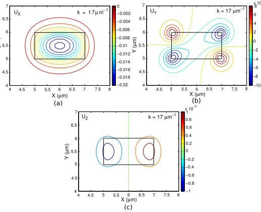
profiles of the fundamental U11x mode at k = 17.0
µm−1 are shown in Fig.2 when the waveguide
X (µm)
Y (
µ
m)
4 4.5 5 5.5 6 6.5 7 7.5 8
4 4.5 5 5.5 6 6.5 7
−0.02
−0.018
−0.016
−0.014
−0.012
−0.01
−0.008
−0.006
−0.004
−0.002
0 UX k = 1 7 µm−1
X (µm)
Y (
µ
m)
4 4.5 5 5.5 6 6.5 7 7.5 8
4 4.5 5 5.5 6 6.5 7
−10
−8
−6
−4
−2
0 2 4 6 8 x 10
U k = 17µm−1
-5
Y
X (µm)
Y (
µ
m)
4 4.5 5 5.5 6 6.5 7 7.5 8
4 4.5 5 5.5 6 6.5 7
−1
−0.8
−0.6
−0.4
−0.2
0 0.2 0.4 0.6 0.8 1 x 10
UZ k = 17µm−1
-3
(a) (b)
(c)
Fig. 2. Ux, Uy and Uz displacement vectors of theU11x
mode.
width, W = 2 µm and its height, H = 1 µm. The outline of the waveguide is shown by solid black lines in the figure. It can be observed that the dominant Ux profile of this mode, shown in
Fig.2a, is nearly Gaussian in shape with its peak value at the center of the waveguide. On the other hand, the non-dominant Uy vector as shown
in Fig.2b, shows a higher order spatial variation with alternative positive and negative peaks at the adjacent corners of the waveguide where its peak value is about 2 orders of magnitude lower than that of the dominant displacement vector,Ux. The
Uz profile is shown in Fig.2c, which illustrates its
positive and negative peaks along the two vertical side walls. Its maximum magnitude is about 5% of the fundamental displacement vector, Ux. In this
case 200x200 mesh divisions were used for the full structure and the corresponding acoustic frequency was 10.044952 GHz. Similarly, for the fundamental
U11y mode, its acoustic frequency was 10.048059 GHz for the same wavenumber, k = 17 µm−1. As the waveguide width and height were not the same, their eigenfrequencies were not exactly the same but yet very close. For this mode, the dominant
Uy displacement vector was Gaussian in shape
(but is not shown here) with its spatial variation was similar to that shown in Fig.2a (similar to the dominant Ux of the U11x mode). For this U
y
11
mode, its non-dominant Ux displacement has four
peaks at the four corners of the waveguide and Uz
[image:4.612.91.260.350.470.2]4
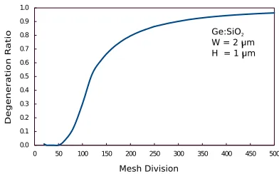
here). The close proximity of two fundamental transverse modes allows these modes to interact and eigenvectors become mixed - this cannot be avoided when the whole structures is simulated as both the eigenmodes appear in close proximity. If a finer mesh division can be used then this mode degeneration will reduce.
The spatial variation of the Uy vector for the
same U11x mode, at k = 17 µm−1, but when mesh division is increased to 500x500 is shown in Fig.3a. This shows the degeneration has reduced, as four peaks at four corners of the waveguide are more clearly visible. It can also be observed that their peak magnitudes are nearly equal (their exact values cannot be identified here, but from the numerical data obtained, they have been identified as +1.2619×10⁻⁴ and −1.2156×10⁻⁴, respectively). However, when a lower mesh is used, the four peaks begin to mix and the positive and negative peaks become unequal and the Uy profile
transforms to show its peak at the center, as shown in Fig.3b, when the mesh division was reduced to 80x80.
X (µm)
Y (
µ
m)
4 4.5 5 5.5 6 6.5 7 7.5 8
4 4.5 5 5.5 6 6.5 7
−1
0 1
x 10−
UY k = 17 µm−1
4 4.5 5 5.5 6 6.5 7 7.5 8
4 4.5 5 5.5 6 6.5 7
−3
−2
−1
0
x 10−
k = 17µm−1 UY
Y (
µ
m)
X (µm)
(a) (b)
4 4
Fig. 3. Uy displacement vectors of theUx
11 mode, when
(a) 500x500 and (b) 80x80 mesh divisions.
To quantify this mode degeneration, next, the ratio of the minimum peaks with the maximum peaks is shown in Fig.4 with the mesh division used. It can be observed that when a higher mesh division is used, in this case 500x500, the positive and negative peaks were almost equal in magnitude, and their ratio was 0.9633. On the other hand, when a smaller mesh is used, in this case 80x80, the larger peak becomes 8.47 times bigger than the smaller peak, and the profile shows a nearly Gaussian shape with its peak value now at the center of the waveguide as shown in Fig.3b. It can be stated that the U11x and U11y modes are mixing up at a progressive rate and non-dominant
Uy vector of the U11x mode is being influenced by
the dominantUy vector of theU11y mode. When the
aspect ratio of the waveguide is increased then this degeneration is reduced as the modal birefringence of the waveguide becomes higher. On the other hand, when the acoustic frequency is reduced, this degeneration is reduced, but not shown here, as the difference between the two similar eigenvalues is increased. However, this modal degeneration between two similar transverse modes cannot be avoided, unless the symmetry of the structures is exploited, as discussed below.
0.0 0.1 0.2 0.3 0.4 0.5 0.6 0.7 0.8 0.9 1.0
0 50 100 150 200 250 300 350 400 450 500 Mesh Division
Degeneration
R
atio
Ge:SiO2
[image:5.612.335.531.206.328.2]W = 2 um H = 1 um
Fig. 4. Degeneration ratio against mesh division forUy
displacement vectors of theU11x mode.
Symmetry conditions of optical waveguides have been extensively exploited [14], whenever they exist, for the modal solutions of optical waveguides. This not only can avoid mode degeneration by separating two interacting modes, but also allow much improved solutions, with a given computer resource. Since this structure has a two-fold sym-metry, only one-quarter of the waveguide needs to be considered, which will allow a much finer mesh division to be used. The combinations of n×U
and n.U at the vertical and horizontal symmetry lines can be used, and there are 4 combinations, which will give all the Umnx and Umny modes, with
various combinations of m and n values, being them odd or even.
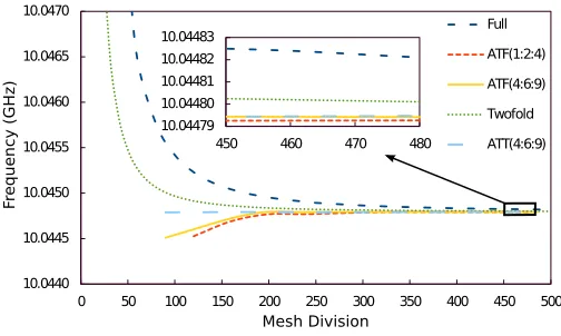
Besides the exploitation of the symmetry condi-tion (if it exists), Aitken’s extrapolacondi-tion [15] tech-nique can also be used to improve the solution accu-racy. To exploit this, the structure must be refined in a fixed geometric ratio. From three successive mesh refinements, final solutions can be extrapo-lated for a possible infinite mesh refinement as given here:
ω∞=ω3−
(ω3−ω2)2
ω3−2ω2+ω1
. (8)
[image:5.612.43.303.374.483.2]successively using higher mesh divisions and ω∞ is
the extrapolated result equivalent to infinite mesh divisions. Here, this geometric ratio does not have to be 1:2:4 but other ratio can also be used, but it should be noted that mesh divisions can only be of integer value and in all the regions the same mesh refinement ratio must be maintained.
Variations of the acoustic frequency of the fundamental U11x mode for k = 17 µm−1 with the mesh division are shown in Fig.5, for both the full and quarter (exploiting the two-fold symmetry) structures. In this case, equal mesh divisions are used in both the transverse directions. It can be noted that as the number of the mesh division is increased, these solutions rapidly converge to their exact solutions. However, it can be easily observed that when 2-fold symmetry is used, as shown by a dotted green line, convergence is much faster than when the full structure is simulated as shown by a dashed blue line. The solution accuracy which can be obtained by a 50x50 mesh divisions for 2-fold symmetry will have the similar accuracy as that of using a 100x100 mesh for the full structure, but requiring a much higher computational resources. Besides that, when Aitken’s extrapolation is used, the solution accuracy is much improved as shown by dashed red line. For the full structure, when the geometric ratio 1:2:4 and 1:1.5:2.25 (or 4:6:9) are used, as identified as ATF(1:2:4) and ATF(4:6:9), and shown by the red dashed and yellow solid lines, respectively, it can be observed that better solution accuracy can be obtained. However, it can be noted that 4:6:9 geometric ratio, shown by a yellow solid line, converges better than use of 1:2:4 (dashed red line). On the other hand, when the 4:6:9 geometric ratio for the quarter structure (exploiting 2-fold symmetry), as shown by a dashed cyan line (ATT(4:6:9)), best solution convergence can be obtained, for a given mesh divi-sion as here both symmetry and extrapolation have been used. To show this region more clearly, an expanded version of this region is shown as an inset.
Following the clear demonstration of the advan-tages of exploiting symmetry conditions and also that of using the Aitken’s extrapolation, dispersion curves of all the transverse Umnx modes are calcu-lated for a 2µm×1µmGe-doped silica waveguide and shown in Fig.6. The variations of their phase velocities with the acoustic frequencies are shown here. For the fundamental U11x mode, as shown by a blue line, it can be observed that when the
10.0440 10.0445 10.0450 10.0455 10.0460 10.0465 10.0470
0 50 100 150 200 250 300 350 400 450 500 Mesh Division
F
requenc
y (GHz)
Full
ATF(1:2:4)
ATF(4:6:9)
Twofold
ATT(4:6:9) 10.04479
10.04480 10.04481 10.04482 10.04483
[image:6.612.309.561.54.205.2]450 460 470 480
Fig. 5. Variation of eigen frequency with the mesh divi-sion for theUx
11mode atk= 17µm−1.
frequency is reduced the phase velocity increases monotonically and reaches that of the cladding shear velocity, VCS, as the mode approaches its
cutoff near 3.59 GHz. It was noted that as the frequency is increased the mode becomes more confined within the core. The full-width-half-maximum (FWHM) of the displacement vectors has been calculated. The FWHM for theU11x mode in the x-direction was 2.9 µm at f = 4 GHz and this value reduces to 1.5 µm when the frequency increases to 16 GHz. For this waveguide, the cutoff frequency of the second mode,Ux
21, shown by a red
line is 7.19 GHz, so this waveguide will support only one transverse mode (with the dominant Ux
displacement) between 3.6-7.2 GHz. It should also be noted that the dispersion curves for the
U12x and U21x are different as the height and width of the waveguide were not the same. Even when the height and width of a waveguide are equal (the waveguide has a 90◦ rotational symmetry), the U21x and U12x modes would be degenerate but by exploiting the symmetry conditions, as shown here, they can be isolated. It should be noted that similar dispersion curves for all the Umny modes
can also be obtained. However, it should be noted that for identical height and width, U12x and U21y
will have the same eigenfrequency and as they also require the same symmetry conditions they cannot be isolated.
6
0 2 4 6 8 10 12 14 16 18 20
[image:7.612.110.556.47.271.2]3680 3690 3700 3710 3720 3730 3740 3750 3760 3770 Frequency (GHz) Phase V elocity (m/ s) UX 11 UX 21 UX 31 UX 41 UX 12 UX 22 UX 32
Fig. 6. Dispersion curves of acoustic shearUx
mn modes.
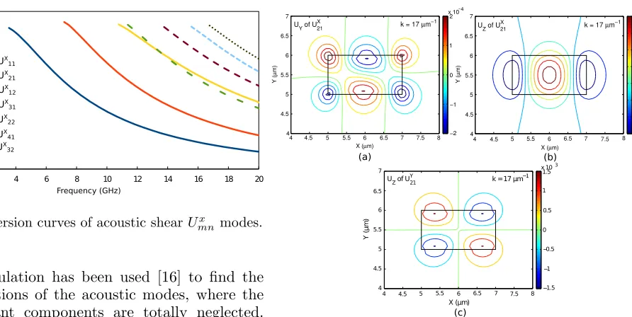
scalar formulation has been used [16] to find the modal solutions of the acoustic modes, where the non-dominant components are totally neglected. For a higher order U21x mode the spatial variation of the two non-dominant components, Uy and Uz
are shown in Fig.7. TheUx profile for this mode is
not shown, but this has two well defined half-wave variations (m=2) along the x-direction and one half-wave variation (n=1) along the y-direction. The Uy profile for the same mode is shown in
Fig.7a, which identifies 3 half-wave (m+1) varia-tions along the x-direction, and 2 half-wave (n+1) variations along they-direction. It has been verified that this relation for the spatial variation of the non-dominant transverse component holds true for all the Umnx modes with m+1 and n+1 half-wave variations along the x and y-directions. This can also be confirmed for the U11x mode as shown in Fig.2. Similarly the Uz profile for the U21x mode,
shown in Fig.7b, shows 3 (=m+1) and 1 (=n) half-wave variations along the x- and y directions, and the same relations has been checked to be true for all Umnx modes. The spatial variations of the non-dominantUx displacement vector for the Umny
modes is not shown here. However, it has been identified during this study that, for these modes it is the non-dominant transverse component, Ux
which will havem+1 andn+1 half-wave variations along thexandy-directions, and its Uz component
will have m and n+1 half-wave variations along the x and y-directions, as shown in Fig.7c for the
U21y mode.
In this study it is shown here that the acoustic modes are fully vectorial in nature and for a trans-verse mode, although its dominant displacement is along one of the transverse direction, however, other two non-dominant (another one transverse and one longitudinal) are also present. This
X (µm)
Y (
µ
m)
4 4.5 5 5.5 6 6.5 7 7.5 8
4 4.5 5 5.5 6 6.5 7 −2 −1 0 1 2
x 10−
UYof U X
21 k = 17 µm−
1
X (µm)
Y (
µ
m)
4 4.5 5 5.5 6 6.5 7 7.5 8
4 4.5 5 5.5 6 6.5 7 −1 −0.5 0 0.5 1 1.5 2 2.5
x 10−
UZof UX
21 k = 17µm
−1 (a) (b) (c) X (µm) Y ( µ m )
4 4.5 5 5.5 6 6.5 7 7.5 8
4 4.5 5 5.5 6 6.5 7 1.5 1 0.5 0 0.5 1 1.5 x 10 U
Zof U
Y
21 k = 17 µm
1 4
3
3
Fig. 7. Displacement fields (a)Uy,(b)UzofU21x and (c)Uz
ofU21y modes.
makes the modes fully hybrid in nature. Similarly, modes in optical waveguides with 2-dimensional confinements are also fully hybrid in nature and this hybridness increases when the index contrast between core and cladding is increased. A study of modal hybridness is important for the calculation of polarization cross-talk [17] or in the design of polarization rotators [18]. Hybridness can be defined as the ratio of the maximum value of the non-dominant component with the maximum value of the dominant components. As for each mode, there are two non-dominant components, so there will be two different hybridness values for each of the modes; however, the ratio between the longitudinal and transverse components is of greatest interest.
For the U11x and U11y modes, the variations of the hybridness with the acoustic frequency are shown in Fig.8. Here the hybridness for the trans-verse modes has been defined as the ratio of the maximum Uz vector to the maximum transverse
displacement, which areUx andUy for theU11x and
U11y modes, respectively. It can be observed that as the frequency is decreased modal hybridness increases and reaches its maximum value and then reduces as the modes approach their cutoff frequencies. The modal hybridness of the U11x,
mode.
2 4 6 8 10 12 14 16 18 20
0.00 0.01 0.02 0.03 0.04 0.05 0.06 0.07 0.08 0.09
Frequency (GHz)
H
yb
ri
d
n
e
ss
UZ/UX in U X
11
UZ/UY in U Y
[image:8.612.62.293.87.218.2]11
Fig. 8. Variation of modal hybridness of two fundamen-tal transverse modes with the frequency
2 4 6 8 10 12 14 16 18 20 0.00
0.02 0.04 0.06 0.08 0.10 0.12 0.14 0.16 0.18 0.20
Frequency (GHz)
H
yb
ri
d
n
e
ss
(
U
z/
U
x) U
X 11
UX
21
UX
31
Fig. 9. Variation of the modal hybridness for the higher order modes.
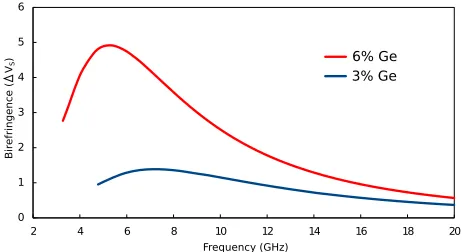
As the waveguide under consideration, with W = 2µmand H= 1µm, does not have a 90◦ rotational symmetry so the propagation velocities of the fun-damental U11x and U11y modes were although close but not identical. For an optical waveguide the difference between the effective indices of the 2 po-larized quasi-TE and quasi-TM modes is known as the modal birefringence. Similarly, here the phase velocities of the U11x and U11y modes are slightly different. The variation of this modal birefringence (but defined here in terms of their phase velocity difference) with the acoustic frequency is shown in Fig.10 by a blue line for the above waveguide. As the frequency is reduced, difference in their phase velocity increases, reaches a maxima, and then decreases. Subsequently another waveguide is studied where Ge-doping is increased to 6%, so that the difference between the shear velocities in the core and cladding, 4VS = VSG−VSC, is now
double. The variation of phase velocity difference
for this guide is shown by a solid red line. In a way similar to that seen in optical waveguides, the modal birefringence is increased as the equivalent acoustic index contrast between core and cladding is increased. The peak birefringence appears at a lower frequency as with higher index contrast the modal cutoff point is also shifted to a lower frequency.
2 4 6 8 10 12 14 16 18 20
0 1 2 3 4 5 6
6% Ge 3% Ge
Frequency (GHz)
Bir
efringence
( V
S
[image:8.612.320.551.177.303.2])
Fig. 10. Variation of modal birefringence with frequency for different Ge doped waveguides.
4. Conclusions
A rigorous full-vectorial acoustic mode solver has been developed by using computationally efficient finite element method. In this work, the advantages of using the symmetry conditions and the type of symmetry walls which can be used are discussed. It is also shown that by using Aitken’s extrapolation the solution accuracy can also be improved with the use of finite computer resources. The spatial variations of the dominant and non-dominant displacement vectors of the acoustic modes are also shown here.
[image:8.612.62.292.291.417.2]8
modal hybridness increases when index contrast is increased. To study the complex interaction be-tween the fully hybrid acoustic modes and optical modes, a full vectorial approach needs to be used, as shown here. The numerical approach presented here can be used for a wide range of practical optical waveguides with either co- or anti-guiding acoustic modes to study their acousto-optical interactions.
References
[1] B. A. Auld, Acoustic Fields and Waves in Solids
(John Wiley & Sons, 1973), Chaps. 1-3.
[2] R. N. Thurston, “Elastic waves in rods and clad
rods,” J. Acoust. Soc. Am.64(1), 1-37 (1978).
[3] A. Safaai-Jazi, “Acoustic modes in optical fiber like waveguides,” IEEE Trans. Ultrason. Ferroelectr.
Freq. Control 35(5), 619-627 (1988).
[4] G. P. Agrawal, Nonlinear Fiber Optics (Academic,
2007), Chap. 9.
[5] R. M. Shelby, M. D. Levenson, and P. W. Bayer, “Guided acoustic wave Brillouin scattering,” Phys.
Rev. B, 31(8), 5244-5252 (1985).
[6] P. Dainese, P. St. J. Russell, N. Joly, J. C. Knight, G. S. Wiederhecker, H. L. Fragnito, V. Laude, and A. Khelif, “Stimulated Brillouin scattering from multi-GHz-guided acoustic phonons in
nanostruc-tured photonic crystal fibers,” Nature Phys.2,
388-392 (2006).
[7] B. M. A. Rahman and A. Agrawal,Finite Element
Modelling Methods for Photonics (Artech, 2013), Chap. 2.
[8] M. Koshiba, S. Mitobe, and M. Suzuki, “Finite-element solution of periodic waveguides for acous-tic waves,” IEEE Trans. Ultrason. Ferroelectr. Freq.
Control UFFC−34(4), 472-477 (1987).
[9] P. E. Lagasse, “Higher-order finite-element
anal-ysis of topographic guides supporting elastic
sur-face waves,” J. Acoust. Soc. Am.53(4), 1116-1122
(1973).
[10] G. O. Stone, “High-order finite elements for in-homogeneous acoustic guiding structures,” IEEE
Trans. Microw. Theory Tech. MTT−21(8),
538-542 (IEEE, 1973).
[11] S. Sriratanavaree, B. M. A. Rahman, D. M. H. Le-ung, N. Kejalakshmy, and K. T. V. Grattan, “Rig-orous characterization of acoustic-optical interac-tions in silicon slot waveguides by full-vectorial
fi-nite element method ”, Opt. Express22, 9528-9536,
(2014).
[12] O. C. Zienkiewicz, The Finite Element Method
(1977).
[13] C. K. Jen, A. Saffaai-Jazi, and G. W. Farnell, “Leaky modes in weakly guiding fiber acoustic waveguides,” IEEE Trans. Ultrason. Ferroelectr.
Freq. Control UFFC−33(6), 619-627 (IEEE,
1986).
[14] B. M. A. Rahman and A. Agrawal,Finite Element
Modelling Methods for Photonics (Artech, 2013), Chap. 3.
[15] B. M. A. Rahman, and J. B. Davies, “Vector-H fi-nite element solution of GaAs/GaAlAs rib
waveg-uide”, IEE Proceedings Pt. J.132, 349-353 (1985).
[16] S. Yoo, C. A. Codemard, Y. Jeong, J. K. Sahu, and J. Nilsson, “Analysis and optimization of acous-tic speed profiles with large transverse variation for mitigation of stimulated Brillouin scattering in
op-tical fibers,” Appl. Opt.49, 1188-1199 (2010).
[17] N. Somasiri and B. M. A. Rahman, “Polarization crosstalk in high index contrast planar silica waveg-uides with slanted sidewalls,” J. Lightwave Technol.
21, 54-60 (2003).
[18] B. M. A. Rahman, S. S. A. Obayya, N. Somasiri, M. Rajarajan, K. T. V. Grattan, and H. A. El-Mikathi, “Design and characterization of compact single-section passive polarization rotator,” J. Lightwave