Internet Security
Cryptographic Principles, Algorithms
and Protocols
Man Young Rhee
School of Electrical and Computer Engineering
Internet Security
Cryptographic Principles, Algorithms
and Protocols
Man Young Rhee
School of Electrical and Computer Engineering
West Sussex PO19 8SQ, England
Telephone (+44) 1243 779777
Email (for orders and customer service enquiries): [email protected] Visit our Home Page on www.wileyeurope.com or www.wiley.com
All Rights Reserved. No part of this publication may be reproduced, stored in a retrieval system or transmitted in any form or by any means, electronic, mechanical, photocopying, recording, scanning or otherwise, except under the terms of the Copyright, Designs and Patents Act 1988 or under the terms of a licence issued by the Copyright Licensing Agency Ltd, 90 Tottenham Court Road, London W1T 4LP, UK, without the permission in writing of the Publisher. Requests to the Publisher should be addressed to the Permissions Department, John Wiley & Sons Ltd, The Atrium, Southern Gate, Chichester, West Sussex PO19 8SQ, England, or emailed to [email protected], or faxed to (+44) 1243 770620.
This publication is designed to provide accurate and authoritative information in regard to the subject matter covered. It is sold on the understanding that the Publisher is not engaged in rendering professional services. If professional advice or other expert assistance is required, the services of a competent professional should be sought.
Other Wiley Editorial Offices
John Wiley & Sons Inc., 111 River Street, Hoboken, NJ 07030, USA
Jossey-Bass, 989 Market Street, San Francisco, CA 94103-1741, USA
Wiley-VCH Verlag GmbH, Boschstr. 12, D-69469 Weinheim, Germany
John Wiley & Sons Australia Ltd, 33 Park Road, Milton, Queensland 4064, Australia
John Wiley & Sons (Asia) Pte Ltd, 2 Clementi Loop #02-01, Jin Xing Distripark, Singapore 129809
John Wiley & Sons Canada Ltd, 22 Worcester Road, Etobicoke, Ontario, Canada M9W 1L1
Wiley also publishes its books in a variety of electronic formats. Some content that appears in print may not be available in electronic books.
Library of Congress Cataloging-in-Publication Data
Rhee, Man Young.
Internet security : cryptographic principles, algorithms, and protocols / Man Young Rhee. p. cm.
Includes bibliographical references and index. ISBN 0-470-85285-2 (alk. paper)
1. Internet – Security measures. 2. Data encryption (Computer Science) 3. Public key cryptography. I. Title.
TK5105.875.I57 .R447 2003-02-05 0058.2 – dc21
2002191050
British Library Cataloguing in Publication Data
A catalogue record for this book is available from the British Library
ISBN 0-470-85285-2
Contents
Author biography xi
Preface xiii
1 Internetworking and Layered Models 1
1.1 Networking Technology 2
1.1.1 Local Area Networks (LANs) 2
1.1.2 Wide Area Networks (WANs) 3
1.2 Connecting Devices 5
1.2.1 Switches 5
1.2.2 Repeaters 6
1.2.3 Bridges 6
1.2.4 Routers 7
1.2.5 Gateways 8
1.3 The OSI Model 8
1.4 TCP/IP Model 12
1.4.1 Network Access Layer 13
1.4.2 Internet Layer 13
1.4.3 Transport Layer 13
1.4.4 Application Layer 13
2 TCP/IP Suite and Internet Stack Protocols 15
2.1 Network Layer Protocols 15
2.1.1 Internet Protocol (IP) 15
2.1.2 Address Resolution Protocol (ARP) 28
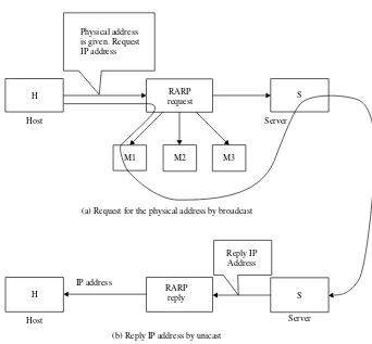
2.1.3 Reverse Address Resolution Protocol (RARP) 31
2.1.4 Classless Interdomain Routing (CIDR) 32
2.1.5 IP Version 6 (IPv6, or IPng) 33
2.1.6 Internet Control Message Protocol (ICMP) 41
2.1.7 Internet Group Management Protocol (IGMP) 41
2.2 Transport Layer Protocols 42
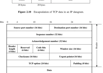
2.2.1 Transmission Control Protocol (TCP) 42
2.3 World Wide Web 47
2.3.1 Hypertext Transfer Protocol (HTTP) 48
2.3.2 Hypertext Markup Language (HTML) 48
2.3.3 Common Gateway Interface (CGI) 49
2.3.4 Java 49
2.4 File Transfer 50
2.4.1 File Transfer Protocol (FTP) 50
2.4.2 Trivial File Transfer Protocol (TFTP) 50
2.4.3 Network File System (NFS) 50
2.5 Electronic Mail 51
2.5.1 Simple Mail Transfer Protocol (SMTP) 51
2.5.2 Post Office Protocol Version 3 (POP3) 52
2.5.3 Internet Message Access Protocol (IMAP) 52
2.5.4 Multipurpose Internet Mail Extension (MIME) 52
2.6 Network Management Service 53
2.6.1 Simple Network Management Protocol (SNMP) 53
2.7 Converting IP Addresses 54
2.7.1 Domain Name System (DNS) 54
2.8 Routing Protocols 54
2.8.1 Routing Information Protocol (RIP) 54
2.8.2 Open Shortest Path First (OSPF) 55
2.8.3 Border Gateway Protocol (BGP) 55
2.9 Remote System Programs 56
2.9.1 TELNET 56
2.9.2 Remote Login (Rlogin) 56
3 Symmetric Block Ciphers 57
3.1 Data Encryption Standard (DES) 57
3.1.1 Description of the Algorithm 58
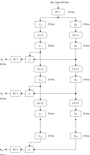
3.1.2 Key Schedule 60
3.1.3 DES Encryption 62
3.1.4 DES Decryption 67
3.1.5 Triple DES 71
3.1.6 DES-CBC Cipher Algorithm with IV 73
3.2 International Data Encryption Algorithm (IDEA) 75
3.2.1 Subkey Generation and Assignment 76
3.2.2 IDEA Encryption 77
3.2.3 IDEA Decryption 82
3.3 RC5 Algorithm 84
3.3.1 Description of RC5 85
3.3.2 Key Expansion 86
3.3.3 Encryption 91
3.3.4 Decryption 92
3.4 RC6 Algorithm 95
3.4.2 Key Schedule 96
3.4.3 Encryption 97
3.4.4 Decryption 100
3.5 AES (Rijndael) Algorithm 107
3.5.1 Notational Conventions 107
3.5.2 Mathematical Operations 108
3.5.3 AES Algorithm Specification 111
4 Hash Function, Message Digest and Message Authentication Code 123
4.1 DMDC Algorithm 123
4.1.1 Key Schedule 124
4.1.2 Computation of Message Digests 128
4.2 Advanced DMDC Algorithm 133
4.2.1 Key Schedule 133
4.2.2 Computation of Message Digests 136
4.3 MD5 Message-digest Algorithm 138
4.3.1 Append Padding Bits 138
4.3.2 Append Length 138
4.3.3 Initialise MD Buffer 138
4.3.4 Define Four Auxiliary Functions (F, G, H, I) 139 4.3.5 FF, GG, HH and II Transformations for Rounds
1, 2, 3 and 4 139
4.3.6 Computation of Four Rounds (64 Steps) 140
4.4 Secure Hash Algorithm (SHA-1) 149
4.4.1 Message Padding 149
4.4.2 Initialise 160-Bit Buffer 150
4.4.3 Functions Used 150
4.4.4 Constants Used 150
4.4.5 Computing the Message Digest 151
4.5 Hashed Message Authentication Codes (HMAC) 155
5 Asymmetric Public-key Cryptosystems 161
5.1 Diffie–Hellman Exponential Key Exchange 161
5.2 RSA Public-key Cryptosystem 165
5.2.1 RSA Encryption Algorithm 165
5.2.2 RSA Signature Scheme 170
5.3 ElGamals Public-key Cryptosystem 172
5.3.1 ElGamal Encryption 173
5.3.2 ElGamal Signatures 175
5.3.3 ElGamal Authentication Scheme 177
5.4 Schnorr’s Public-key Cryptosystem 179
5.4.1 Schnorr’s Authentication Algorithm 179
5.4.2 Schnorr’s Signature Algorithm 181
5.6 The Elliptic Curve Cryptosystem (ECC) 187
5.6.1 Elliptic Curves 187
5.6.2 Elliptic Curve Cryptosystem Applied to the ElGamal
Algorithm 195
5.6.3 Elliptic Curve Digital Signature Algorithm 196
5.6.4 ECDSA Signature Computation 198
6 Public-key Infrastructure 201
6.1 Internet Publications for Standards 202
6.2 Digital Signing Techniques 203
6.3 Functional Roles of PKI Entities 210
6.3.1 Policy Approval Authority 210
6.3.2 Policy Certification Authority 212
6.3.3 Certification Authority 213
6.3.4 Organisational Registration Authority 214
6.4 Key Elements for PKI Operations 215
6.4.1 Hierarchical Tree Structures 216
6.4.2 Policy-making Authority 217
6.4.3 Cross-certification 218
6.4.4 X.500 Distinguished Naming 221
6.4.5 Secure Key Generation and Distribution 222
6.5 X.509 Certificate Formats 222
6.5.1 X.509 v1 Certificate Format 223
6.5.2 X.509 v2 Certificate Format 225
6.5.3 X.509 v3 Certificate Format 226
6.6 Certificate Revocation List 233
6.6.1 CRL Fields 234
6.6.2 CRL Extensions 235
6.6.3 CRL Entry Extensions 237
6.7 Certification Path Validation 238
6.7.1 Basic Path Validation 239
6.7.2 Extending Path Validation 240
7 Network Layer Security 243
7.1 IPsec Protocol 243
7.1.1 IPsec Protocol Documents 244
7.1.2 Security Associations (SAs) 246
7.1.3 Hashed Message Authentication Code (HMAC) 248
7.2 IP Authentication Header 250
7.2.1 AH Format 251
7.2.2 AH Location 253
7.3 IP ESP 253
7.3.1 ESP Packet Format 254
7.3.2 ESP Header Location 256
7.4 Key Management Protocol for IPsec 260
7.4.1 OAKLEY Key Determination Protocol 260
7.4.2 ISAKMP 261
8 Transport Layer Security: SSLv3 and TLSv1 277
8.1 SSL Protocol 277
8.1.1 Session and Connection States 278
8.1.2 SSL Record Protocol 279
8.1.3 SSL Change Cipher Spec Protocol 282
8.1.4 SSL Alert Protocol 283
8.1.5 SSL Handshake Protocol 284
8.2 Cryptographic Computations 290
8.2.1 Computing the Master Secret 290
8.2.2 Converting the Master Secret into Cryptographic
Parameters 291
8.3 TLS Protocol 293
8.3.1 HMAC Algorithm 293
8.3.2 Pseudo-random Function 296
8.3.3 Error Alerts 300
8.3.4 Certificate Verify Message 302
8.3.5 Finished Message 302
8.3.6 Cryptographic Computations (For TLS) 302
9 Electronic Mail Security: PGP, S/MIME 305
9.1 PGP 305
9.1.1 Confidentiality via Encryption 306
9.1.2 Authentication via Digital Signature 307
9.1.3 Compression 308
9.1.4 Radix-64 Conversion 309
9.1.5 Packet Headers 313
9.1.6 PGP Packet Structure 315
9.1.7 Key Material Packet 319
9.1.8 Algorithms for PGP 5.x 323
9.2 S/MIME 324
9.2.1 MIME 325
9.2.2 S/MIME 331
9.2.3 Enhanced Security Services for S/MIME 335
10 Internet Firewalls for Trusted Systems 339
10.1 Role of Firewalls 339
10.2 Firewall-Related Terminology 340
10.2.1 Bastion Host 341
10.2.2 Proxy Server 341
10.2.3 SOCKS 342
10.2.5 De-militarised Zone (DMZ) 343
10.2.6 Logging and Alarms 343
10.2.7 VPN 344
10.3 Types of Firewalls 344
10.3.1 Packet Filters 344
10.3.2 Circuit-level Gateways 349
10.3.3 Application-level Gateways 349
10.4 Firewall Designs 350
10.4.1 Screened Host Firewall (Single-homed Bastion Host) 351 10.4.2 Screened Host Firewall (Dual-homed Bastion Host) 351
10.4.3 Screened Subnet Firewall 352
11 SET for E-commerce Transactions 355
11.1 Business Requirements for SET 355
11.2 SET System Participants 357
11.3 Cryptographic Operation Principles 358
11.4 Dual Signature and Signature Verification 359
11.5 Authentication and Message Integrity 363
11.6 Payment Processing 366
11.6.1 Cardholder Registration 366
11.6.2 Merchant Registration 371
11.6.3 Purchase Request 373
11.6.4 Payment Authorisation 374
11.6.5 Payment Capture 376
Acronyms 379
Bibliography 383
About the Author
Man Young Rhee received his B.S.E.E degree from Seoul National University in 1952 and his M.S.E.E and Ph.D. degree from the University of Colorado in 1956 and 1958, respectively. Since 1997, Dr. Rhee is an Invited Professor of Electrical and Computer Engineering, Seoul National University. He is also Professor Emeritus of Electrical Engi-neering at Hanyang University, Seoul, Korea. At the same university he served as Vice President. Dr. Rhee taught at the Virginia Polytechnic Institute and State University (U.S.A.) as a professor and was employed at the Jet Propulsion Laboratory, California Institute of Technology.
In Korea, he was Vice President of the Agency for Defense Development, Ministry of National Defense, R.O.K.; President of the Korea Telecommunications Company (dur-ing 1977–79 the ESS Telephone Exchange system was first developed in Korea); and President of the Samsung Semiconductor and Telecommunications Company.
From 1990 to 1997 he was President of the Korea Institute of Information Security and Cryptology. During the year 1996–99, he served as Chairman of the Board of Direc-tors, Korea Information Security Agency, Ministry of Information and Communication, R.O.K.
Dr. Rhee is a member of the National Academy of Sciences, Senior Fellow of the Korea Academy of Science and Technology, and honorary member of the National Academy of Engineering of Korea. He was a recipient of the Outstanding Scholastic Achievement Prize from the National Academy of Sciences, R.O.K. He was also awarded the NAEK Grand Prize from the National Academy of Engineering of Korea.
Dr. Rhee is the author of four books:Error Correcting Coding Theory(McGraw-Hill, 1989),Cryptography and Secure Communications(McGraw- Hill, 1994),CDMA Cellular Mobile Communications and Network Security(Prentice Hall, 1998) andInternet Security
(John Wiley, 2003). His CDMA book was recently translated into Japanese (2001) and Chinese (2002), respectively.
His research interests include cryptography, error correcting coding, wireless Internet security and CDMA mobile communications.
Preface
The Internet is global in scope, but this global internetwork is an open insecure medium. The Internet has revolutionised the computing and communications world for the purpose of development and support of client and server services. The availability of the Internet, along with powerful affordable computing and communications, has made possible a new paradigm of commercial world. This has been tremendously accelerated by the adoption of browsers and World Wide Web technology, allowing users easy access to information linked throughout the globe. The Internet has truly proven to be an essential vehicle of information trade today.
The Internet is today a widespread information infrastructure, a mechanism for infor-mation dissemination, and a medium for collaboration and interaction between individuals, government agencies, financial institutions, academic circles and businesses of all sizes, without regard for geographic location.
People have become increasingly dependent on the Internet for personal and profes-sional use regardless of whether it is for e-mail, file transfer, remote login, Web page access or commercial transactions. With the increased awareness and popularity of the Internet, Internet security problems have been brought to the fore. Internet security is not only extremely important, but more technically complex than in the past. The mere fact that business is being performed online over an insecure medium is enough to entice criminal activity to the Internet.
The Internet access often creates a threat as a security flaw. To protect users from Internet-based attacks and to provide adequate solutions when security is imposed, cryptographic techniques must be employed to solve these problems. This book is designed to reflect the central role of cryptographic operations, principles, algorithms and protocols in Internet security. The remedy for all kinds of threats created by criminal activities should rely on cryptographic resolution. Authentication, message integrity and encryption are very impor-tant in cultivating, improving, and promoting Internet security. Without such authentication procedures, an attacker could impersonate anyone and then gain access to the network. Message integrity is required because data may be altered as it travels through the Internet. Without confidentiality by encryption, information may become truly public.
consists of 11 chapters and focuses on the critical security issues related to the Internet. The following is a summary of the contents of each chapter.
Chapter 1 begins with a brief history of the Internet and describes topics covering (1) networking fundamentals such as LANs (Ethernet, Token Ring, FDDI), WANs (Frame Relay, X.25, PPP) and ATM; (2) connecting devices such as circuit- and packet-switches, repeaters, bridges, routers, and gateways; (3) the OSI model which specifies the function-ality of its seven layers; and finally (4) a TCP/IP five-layer suite providing a hierarchical protocol made up of physical standards, a network interface and internetworking.
Chapter 2 presents a state-of-the-art survey of the TCP/IP suite. Topics covered include (1) TCP/IP network layer protocols such as ICMP, IP version 4 and IP version 6 relat-ing to the IP packet format, addressrelat-ing (includrelat-ing ARP, RARP and CIDR) and rout-ing; (2) transport layer protocols such as TCP and UDP; (3) HTTP for the World Wide Web; (4) FTP, TFTP and NFS protocols for file transfer; (5) SMTP, POP3, IMAP and MIME for e-mail; and (6) SNMP protocol for network management.
Chapter 3 deals with some of the important contemporary block cipher algorithms that have been developed over recent years with an emphasis on the most widely used encryp-tion techniques such as Data Encrypencryp-tion Standard (DES), Internaencryp-tional Data Encrypencryp-tion Algorithm (IDEA), the RC5 and RC6 encryption algorithms, and Advanced Encryption Standard (AES). AES specifies an FIPS-approved Rijndael algorithm (2001) that can pro-cess data blocks of 128 bits, using cipher keys with lengths of 128, 192 and 256 bits. DES is not new, but it has survived remarkably well over 20 years of intense cryptanal-ysis. The complete analysis of triple DES-EDE in CBC mode is also included., Pretty Good Privacy (PGP) used for electronic mail (e-mail) and file storage applications utilises IDEA for conventional block encryption, along with RSA for public key encryption and MD5 for hash coding. RC5 and RC6 are both parameterised block algorithms of variable size, variable number of rounds, and a variable-length key. They are designed for great flexibility in both performance and level of security.
Chapter 4 covers the various authentication techniques based on digital signatures. It is often necessary for communication parties to verify each other’s identity. One practical way to do this is the use of cryptographic authentication protocols employing a one-way hash function. Several contemporary hash functions (such as DMDC, MD5 and SHA-1) are introduced to compute message digests or hash codes for providing a systematic approach to authentication. This chapter also extends the discussion to include the Internet standard HMAC, which is a secure digest of protected data. HMAC is used with a variety of different hash algorithms, including MD5 and SHA-1. Transport Layer Security (TLS) also makes use of the HMAC algorithm.
Chapter 5 describes several public-key cryptosystems brought in after conventional encryption. This chapter concentrates on their use in providing techniques for public-key encryption, digital signature and authentication. This chapter covers in detail the widely used Diffie–Hellman key exchange technique (1976), the Rivest–Schamir–Adleman (RSA) algorithm (1978), the ElGamal algorithm (1985), the Schnorr algorithm (1990), the Digital Signature Algorithm (DSA, 1991) and the Elliptic Curve Cryptosystem (ECC, 1985) and Elliptic Curve Digital Signature Algorithm (ECDSA, 1999).
Policy Approval Authority (PAA) is the root of the certificate management infrastructure. This authority is known to all entities at entire levels in the PKI, and creates guidelines that all users, CAs and subordinate policy-making authorities must follow. Policy Certificate Authorities (PCAs) are formed by all entities at the second level of the infrastructure. PCAs must publish their security policies, procedures, legal issues, fees and any other subjects they may consider necessary. Certification Authorities (CAs) form the next level below the PCAs. The PKI contains many CAs that have no policy-making responsibilities. A CA has any combination of users and RAs whom it certifies. The primary function of the CA is to generate and manage the public-key certificates that bind the user’s identity with the user’s public key. The Registration Authority (RA) is the interface between a user and a CA. The primary function of the RA is user identification and authentication on behalf of a CA. It also delivers the CA-generated certificate to the end user. X.500 specifies the directory service. X.509 describes the authentication service using the X.500 directory. X.509 certificates have evolved through three versions: version 1 in 1988, version 2 in 1993 and version 3 in 1996. X.509 v3 is now found in numerous products and Internet standards. These three versions are explained in turn. Finally, Certificate Revocation Lists (CRLs) are used to list unexpired certificates that have been revoked. CRLs may be revoked for a variety of reasons, ranging from routine administrative revocations to situations where private keys are compromised. This chapter also includes the certification path validation procedure for the Internet PKI and architectural structures for the PKI certificate management infrastructure.
Chapter 7 describes the IPsec protocol for network layer security. IPsec provides the capability to secure communications across a LAN, across a virtual private network (VPN) over the Internet or over a public WAN. Provision of IPsec enables a business to rely heav-ily on the Internet. The IPsec protocol is a set of security extensions developed by IETF to provide privacy and authentication services at the IP layer using cryptographic algorithms and protocols. To protect the contents of an IP datagram, there are two main transfor-mation types: the Authentication Header (AH) and the Encapsulating Security Payload (ESP). These are protocols to provide connectionless integrity, data origin authentication, confidentiality and an anti-replay service. A Security Association (SA) is fundamental to IPsec. Both AH and ESP make use of a SA that is a simple connection between a sender and receiver, providing security services to the traffic carried on it. This chapter also includes the OAKLEY key determination protocol and ISAKMP.
most important part of SSL or TLS. The Handshake Protocol consists of a series of mes-sages exchanged by client and server. This protocol provides three services between the server and client. The Handshake Protocol allows the client/server to agree on a protocol version, to authenticate each other by forming a MAC, and to negotiate an encryption algorithm and cryptographic keys for protecting data sent in an SSL record before the application protocol transmits or receives its first byte of data.
A keyed hashing message authentication code (HMAC) is a secure digest of some protected data. Forging an HMAC is impossible without knowledge of the MAC secret. HMAC can be used with a variety of different hash algorithms: MD5 and SHA-1, denoting these as HMAC-MD5 (secret, data) and SHA-1 (secret, data). There are two differences between the SSLv3 scheme and the TLS MAC scheme: TSL makes use of the HMAC algorithm defined in RFC 2104; and TLS master-secret computation is also different from that of SSLv3.
Chapter 9 describes e-mail security. Pretty Good Privacy (PGP), invented by Philip Zimmermann, is widely used in both individual and commercial versions that run on a variety of platforms throughout the global computer community. PGP uses a combination of symmetric secret-key and asymmetric public-key encryption to provide security services for e-mail and data files. PGP also provides data integrity services for messages and data files using digital signatures, encryption, compression (ZIP) and radix-64 conversion (ASCII Armor). With growing reliance on e-mail and file storage, authentication and confidentiality services are increasingly important. Multipurpose Internet Mail Extension (MIME) is an extension to the RFC 822 framework which defines a format for text messages sent using e-mail. MIME is actually intended to address some of the problems and limitations of the use of SMTP. S/MIME is a security enhancement to the MIME Internet e-mail format standard, based on technology from RSA Data Security. Although both PGP and S/MIME are on an IETF standards track, it appears likely that PGP will remain the choice for personal e-mail security for many users, while S/MIME will emerge as the industry standard for commercial and organisational use. The two PGP and S/MIME schemes are covered in this chapter.
Chapter 10 discusses the topic of firewalls as an effective means of protecting an internal system from Internet-based security threats. A firewall is a security gateway that controls access between the public Internet and a private internal network (or intranet). A firewall is an agent that screens network traffic in some way, blocking traffic it believes to be inappropriate, dangerous or both. The security concerns that inevitably arise between the sometimes hostile Internet and secure intranets are often dealt with by inserting one or more firewalls on the path between the Internet and the internal network. In reality, Internet access provides benefits to individual users, government agencies and most organisations. But this access often creates a security threat.
classified into three main categories: packet filters, circuit-level gateways and application-level gateways. In this chapter, each of these firewalls is examined in turn. Finally, this chapter discusses screened host firewalls and how to implement a firewall strategy. To provide a certain level of security, the three basic firewall designs are considered: a single-homed bastion host, a dual-homed bastion host and a screened subnet firewall.
Chapter 11 covers the SET protocol designed for protecting credit card transactions over the Internet. The recent explosion in e-commerce has created huge opportunities for consumers, retailers and financial institutions alike. SET relies on cryptography and X.509 v3 digital certificates to ensure message confidentiality, payment integrity and identity authentication. Using SET, consumers and merchants are protected by ensuring that payment information is safe and can only be accessed by the intended recipient. SET combats the risk of transaction information being altered in transit by keeping information securely encrypted at all times and by using digital certificates to verify the identity of those accessing payment details. SET is the only Internet transaction protocol to provide security through authentication. Message data is encrypted with a random symmetric key which is then encrypted using the recipient’s public key. The encrypted message, along with this digital envelope, is sent to the recipient. The recipient decrypts the digital envelope with a private key and then uses the symmetric key to recover the original message. SET addresses the anonymity of Internet shopping by using digital signatures and digital certificates to authenticate the banking relationships of cardholders and merchants. How to ensure secure payment card transactions on the Internet is fully explored in this chapter.
The scope of this book is adequate to span a one- or two-semester course at a senior or first-year graduate level. As a reference book, it will be useful to computer engineers, communications engineers and system engineers. It is also suitable for self-study. The book is intended for use in both academic and professional circles, and it is also suitable for corporate training programmes or seminars for industrial organisations as well as research institutes. At the end of the book, there is a list of frequently used acronyms, and a bibliography.
1
Internetworking and Layered Models
The Internet today is a widespread information infrastructure, but it is inherently an insecure channel for sending messages. When a message (or packet) is sent from one Website to another, the data contained in the message are routed through a number of intermediate sites before reaching its destination. The Internet was designed to accom-modate heterogeneous platforms so that people who are using different computers and operating systems can communicate. The history of the Internet is complex and involves many aspects – technological, organisational and community. The Internet concept has been a big step along the path towards electronic commerce, information acquisition and community operations.
Early ARPANET researchers accomplished the initial demonstrations of packet-switching technology. In the late 1970s, the growth of the Internet was recognised and subsequently a growth in the size of the interested research community was accompanied by an increased need for a coordination mechanism. The Defense Advanced Research Projects Agency (DARPA) then formed an International Cooperation Board (ICB) to coordinate activities with some European countries centered on packet satellite research, while the Internet Configuration Control Board (ICCB) assisted DARPA in managing Internet activity. In 1983, DARPA recognised that the continuing growth of the Internet community demanded a restructuring of coordination mechanisms. The ICCB was dis-banded and in its place the Internet Activities Board (IAB) was formed from the chairs of the Task Forces. The IAB revitalised the Internet Engineering Task Force (IETF) as a member of the IAB. By 1985, there was a tremendous growth in the more practical engineering side of the Internet. This growth resulted in the creation of a substructure to the IETF in the form of working groups. DARPA was no longer the major player in the funding of the Internet. Since then, there has been a significant decrease in Internet activity at DARPA. The IAB recognised the increasing importance of IETF, and restruc-tured to recognise the Internet Engineering Steering Group (IESG) as the major standards review body. The IAB also restructured to create the Internet Research Task Force (IRTF) along with the IETF.
Internet Security. Edited by M.Y. Rhee
Since the early 1980s, the Internet has grown beyond its primarily research roots, to include both a broad user community and increased commercial activity. This growth in the commercial sector brought increasing concern regarding the standards process. Increased attention was paid to making progress, eventually leading to the formation of the Internet Society in 1991. In 1992, the Internet Activities Board was reorganised and renamed the Internet Architecture board (IAB) operating under the auspices of the Internet Society. The mutually supportive relationship between the new IAB, IESG and IETF led to them taking more responsibility for the approval of standards, along with the provision of services and other measures which would facilitate the work of the IETF.
1.1
Networking Technology
Data signals are transmitted from one device to another using one or more types of transmission media, including twisted-pair cable, coaxial cable and fibre-optic cable. A message to be transmitted is the basic unit of network communications. A message may consist of one or more cells, frames or packets which are the elemental units for network communications. Networking technology includes everything from local area networks (LANs) in a limited geographic area such as a single building, department or campus to wide area networks (WANs) over large geographical areas that may comprise a country, a continent or even the whole world.
1.1.1
Local Area Networks (LANs)
A local area network (LAN) is a communication system that allows a number of indepen-dent devices to communicate directly with each other in a limited geographic area such as a single office building, a warehouse or a campus. LANs are standardised by three architectural structures: Ethernet, token ring and fibre distributed data interface (FDDI).
1.1.1.1 Ethernet
Ethernet is a LAN standard originally developed by Xerox and later extended by a joint venture between Digital Equipment Corporation (DEC), Intel Corporation and Xerox. The access mechanism used in an Ethernet is called Carrier Sense Multiple Access with Collision Detection (CSMA/CD). In CSMA/CD, before a station transmits data, it must check the medium where any other station is currently using the medium. If no other station is transmitting, the station can send its data. If two or more stations send data at the same time, it may result in a collision. Therefore, all stations should continuously check the medium to detect any collision. If a collision occurs, all stations ignore the data received. The sending stations wait for a period of time before resending the data. To reduce the possibility of a second collision, the sending stations individually generate a random number that determinates how long the station should wait before resending data.
1.1.1.2 Token Ring
attempt to send data many times before a transmission captures a perfect link. This redundancy can create delays of indeterminable length if traffic is heavy. There is no way to predict either the occurrence of collisions or the delays produced by multiple stations attempting to capture the link at the same time. Token ring resolves this uncertainty by making stations take turns in sending data.
As an access method, the token is passed from station to station in sequence until it encounters a station with data to send. The station to be sent data waits for the token. The station then captures the token and sends its data frame. This data frame proceeds around the ring and each station regenerates the frame. Each intermediate station examines the destination address, finds that the frame is addressed to another station, and relays it to its neighbouring station. The intended recipient recognises its own address, copies the message, checks for errors and changes four bits in the last byte of the frame to indicate that the address has been recognised and the frame copied. The full packet then continues around the ring until it returns to the station that sent it.
1.1.1.3 Fiber Distributed Data Interface (FDDI)
FDDI is a LAN protocol standardised by ANSI and ITU-T. It supports data rates of 100 Mbps and provides a high-speed alternative to Ethernet and token ring. When FDDI was designed, the data rate of 100 Mbps required fibre-optic cable.
The access method in FDDI is also called token passing. In a token ring network, a station can send only one frame each time it captures the token. In FDDI, the token passing mechanism is slightly different in that access is limited by time. Each station keeps a timer which shows when the token should leave the station. If a station receives the token earlier than the designated time, it can keep the token and send data until the scheduled leaving time. On the other hand, if a station receives the token at the designated time or later than this time, it should let the token pass to the next station and wait for its next turn.
FDDI is implemented as a dual ring. In most cases, data transmission is confined to the primary ring. The secondary ring is provided in case of the primary ring’s failure. When a problem occurs on the primary ring, the secondary ring can be activated to complete data circuits and maintain service.
1.1.2
Wide Area Networks (WANs)
A WAN provides long-distance transmission of data, voice, image and video information over large geographical areas that may comprise a country, a continent or even the world. In contrast to LANs (which depend on their own hardware for transmission), WANs can utilise public, leased or private communication devices, usually in combination.
1.1.2.1 PPP
• Flag field:Each frame starts with a one-byte flag whose value is 7E(0111 1110). The flag is used for synchronisation at the bit level between the sender and receiver.
• Address field:This field has the value of FF(1111 1111).
• Control field: This field has the value of 03(0000 0011).
• Protocol field: This is a two-byte field whose value is 0021(0000 0000 0010 0001)
for TCP/IP.
• Data field:The data field ranges up to 1500 bytes.
• CRC: This is a two-byte cyclic redundancy check. Cyclic redundancy check (CRC) is implemented in the physical layer for use in the data link layer. A sequence of redundant bits (CRC) is appended to the end of a data unit so that the resulting data unit becomes exactly divisible by a predetermined binary number. At its destination, the incoming data unit is divided by the same number. If there is no remainder, the data unit is accepted. If a remainder exists, the data unit has been damaged in transit and therefore must be rejected.
1.1.2.2 X.25
X.25 is widely used, as the packet switching protocol provided for use in a WAN. It was developed by the ITU-T in 1976. X.25 is an interface between data terminal equipment and data circuit terminating equipment for terminal operations at the packet mode on a public data network.
X.25 defines how a packet mode terminal can be connected to a packet network for the exchange of data. It describes the procedures necessary for establishing connection, data exchange, acknowledgement, flow control and data control.
1.1.2.3 Frame Relay
Frame relay is a WAN protocol designed in response to X.25 deficiencies. X.25 provides extensive error-checking and flow control. Packets are checked for accuracy at each station to which they are routed. Each station keeps a copy of the original frame until it receives confirmation from the next station that the frame has arrived intact. Such station-to-station checking is implemented at the data link layer of the OSI model, but X.25 only checks for errors from source to receiver at the network layer. The source keeps a copy of the original packet until it receives confirmation from the final destination. Much of the traffic on an X.25 network is devoted to error-checking to ensure reliability of service. Frame relay does not provide error-checking or require acknowledgement in the data link layer. Instead, all error-checking is left to the protocols at the network and transport layers, which use the frame relay service. Frame relay only operates at the physical and data link layer.
1.1.2.4 Asynchronous Transfer Mode (ATM)
The header contains a virtual path identifier (VPI) and a virtual channel identifier (VCI). These two identifiers are used to route the cell through the network to the final destination. An ATM network is a connection-oriented cell switching network. This means that the unit of data is not a packet as in a packet switching network, or a frame as in a frame relay, but a cell. However, ATM, like X.25 and frame relay, is a connection-oriented network, which means that before two systems can communicate, they must make a connection. To start up a connection, a system uses a 20-byte address. After the connection is established, the combination of VPI/VCI leads a cell from its source to its final destination.
1.2
Connecting Devices
Connecting devices are used to connect the segments of a network together or to connect networks to create an internetwork. These devices are classified into five categories: switches, repeaters, bridges, routers and gateways. Each of these devices except the first one (switches) interacts with protocols at different layers of the OSI model.
Repeaters forward all electrical signals and are active only at the physical layer. Bridges store and forward complete packets and affect the flow control of a single LAN. Bridges are active at the physical and data link layers. Routers provide links between two separate LANs and are active in the physical, data link and network layers. Finally, gateways provide translation services between incompatible LANs or applications, and are active in all layers.
Connection devices that interact with protocols at different layers of the OSI model are shown in Figure 1.1.
1.2.1
Switches
A switched network consists of a series of interlinked switches. Switches are hard-ware/software devices capable of creating temporary connections between two or more devices to the switch but not to each other. Switching mechanisms are generally classified into three methods: circuit switching, packet switching and message switching.
Physical (L1) Data link (L2) Network (L3) Transport (L4) Session (L5) Presentation (L6) Application (L7)
Gateway
Router
Bridge
Repeater
• Circuit switching creates a direct physical connection between two devices such as telephones or computers. Once a connection is made between two systems, circuit switching creates a dedicated path between two end users. The end users can use the path for as long as they want.
• Packet switching is one way to provide a reasonable solution for data transmission. In a packet-switched network, data are transmitted in discrete units of variable-length blocks called packets. Each packet contains not only data, but also a header with control information. The packets are sent over the network node to node. At each node, the packet is stored briefly before being routed according to the information in its header.
In the datagram approach to packet switching, each packet is treated independently of all others as though it exists alone. In the virtual circuit approach to packet switch-ing, if a single route is chosen between sender and receiver at the beginning of the session, all packets travel one after another along that route. Although these two approaches seem the same, there exists a fundamental difference between them. In circuit switching, the path between the two end users consists of only one channel. In the virtual circuit, the line is not dedicated to two users. The line is divided into channels and each channel can use one of the channels in a link.
• Message switching is known as the store and forwarding method. In this approach, a computer (or a node) receives a message, stores it until the appropriate route is free, then sends it out. This method has now been phased out.
1.2.2
Repeaters
A repeater is an electronic device that operates on the physical layer only of the OSI model. A repeater boosts the transmission signal from one segment and continues the signal to another segment. Thus, a repeater allows us to extend the physical length of a network. Signals that carry information can travel a limited distance within a network before degradation of the data integrity due to noise. A repeater receives the signal before attenuation, regenerates the original bit pattern and puts the restored copy back on to the link.
1.2.3
Bridges
Bridges operate in both the physical and the data link layers of the OSI model. A sin-gle bridge connects different types of networks together and promotes interconnectivity between networks. Bridges divide a large network into smaller segments. Unlike repeaters, bridges contain logic that allows them to keep separate the traffic for each segment. Bridges are smart enough to relay a frame towards the intended recipient so that traffic can be filtered. In fact, this filtering operation makes bridges useful for controlling congestion, isolating problem links and promoting security through this partitioning of traffic.
a match, it discovers to which segment the station belongs and relays the packet to that segment only.
1.2.4
Routers
Routers operate in the physical, data link and network layers of the OSI model. The Internet is a combination of networks connected by routers. When a datagram goes from a source to a destination, it will probably pass through many routers until it reaches the router attached to the destination network. Routers determine the path a packet should take. Routers relay packets among multiple interconnected networks. In particular, an IP router forwards IP datagrams among the networks to which it connects. A router uses the destination address on a datagram to choose a next-hop to which it forwards the datagram. A packet sent from a station on one network to a station on a neighbouring network goes first to a jointly held router, which switches it over the destination network. In fact, the easiest way to build the Internet is to connect two or more networks with a router. Routers provide connections to many different types of physical networks: Ethernet, token ring, point-to-point links, FDDI and so on.
• The routing module receives an IP packet from the processing module. If the packet is to be forwarded, it should be passed to the routing module. It finds the IP address of the next station along with the interface number from which the packet should be sent. It then sends the packet with information to the fragmentation module. The fragmentation module consults the MTU table to find the maximum transfer unit (MTU) for the specific interface number.
• The routing table is used by the routing module to determine the next-hop address of the packet. Every router keeps a routing table that has one entry for each destination network. The entry consists of the destination network IP address, the shortest distance to reach the destination in hop count, and the next router (next hop) to which the packet should be delivered to reach its final destination. The hop count is the number of networks a packet enters to reach its final destination. A router should have a routing table to consult when a packet is ready to be forwarded. The routing table should specify the optimum path for the packet. The table can be either static or dynamic. A static table is one that is not changed frequently, but a dynamic table is one that is updated automatically when there is a change somewhere in the Internet. Today, the Internet needs dynamic routing tables.
totally differently. The policy criterion in BGP is set by the administrator. The policy defines the paths that should be chosen.
1.2.5
Gateways
Gateways operate over the entire range in all seven layers of the OSI model. Internet routing devices have traditionally been called gateways. A gateway is a protocol converter which connects two or more heterogeneous systems and translates among them. The gateway thus refers to a device that performs protocol translation between devices. A gateway can accept a packet formatted for one protocol and convert it to a packet formatted for another protocol before forwarding it. The gateway understands the protocol used by each network linked into the router and is therefore able to translate from one to another.
1.3
The OSI Model
The Ethernet, originally called the Alto Aloha network, was designed by the Xerox Palo Alto Research Center in 1973 to provide communication for research and development CP/M computers. When in 1976 Xerox started to develop the Ethernet as a 20 Mbps product, the network prototype was called the Xerox Wire. In 1980, when the Digital, Intel and Xerox standard was published to make it a LAN standard at 10 Mbps, Xerox Wire changed its name back to Ethernet. Ethernet became a commercial product in 1980 at 10 Mbps. The IEEE called its Ethernet 802.3 standard CSMA/CD (or carrier sense multiple access with collision detection). As the 802.3 standard evolved, it has acquired such names as Thicknet (IEEE 10Base-5), Thinnet or Cheapernet (10Base-2), Twisted Ethernet (10Base-T) and Fast Ethernet (100Base-T).
The design of Ethernet preceded the development of the seven-layer OSI model. The Open System Interconnect (OSI) model was developed and published in 1982 by the International Organisation for Standardisation (ISO) as a generic model for data com-munication. The OSI model is useful because it is a broadly based document, widely available and often referenced. Since modularity of communication functions is a key design criterion in the OSI model, vendors who adhere to the standards and guidelines of this model can supply Ethernet-compatible devices, alternative Ethernet channels, higher-performance Ethernet networks and bridging protocols that easily and reliably connect other types of data network to Ethernet.
Since the OSI model was developed after Ethernet and Signaling System #7 (SS7), there are obviously some discrepancies between these three protocols. Yet the functions and processes outlined in the OSI model were already in practice when Ethernet or SS7 was developed. In fact, SS7 networks use point-to-point configurations between signalling points. Due to the point-to-point configurations and the nature of the transmissions, the simple data link layer does not require much complexity.
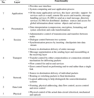
Functionality OSI
Layer Layer
No.
• Provides user interface
• System computing and user application process
• Of the many application services, this layer provides support for services such as e-mail, remote file access and transfer, message handling services (X.400) to send an e-mail message, directory services (X.500) for distributed database sources and access for global information about various objects and services
Application 7
• Administrative control of transmissions and transfers between nodes
• Dialogue control between two systems
• Synchronisation process by inserting checkpoints into data stream
Session 5
• Data interpretation (compression, encryption, formatting and syntax selection) and code transformations
Presentation 6
• Physical control of the actual data circuit (electrical, mechanical and optical)
Physical 1
• Framing, physical addressing, data flow control, access control and error control
Data Link 2
• Source-to-destination delivery of individual packets • Routing or switching packets to final destination
• Logical addressing to help distinguish the source/destination systems
Network 3
• Source-to-destination delivery of entire message
• Message segmentation at the sending layer and reassembling at the receiving layer
• Transfer control by either connectionless or connection-oriented mechanism for delivering packets
• Flow control for end-to-end services
• Error control based on performing end-to-end rather than a single link
[image:30.476.78.400.82.420.2]Transport 4
Figure 1.2 ISO/OSI model.
and the future growth of network technology. Implementations of the OSI model stip-ulate communication between layers on two processors and an interface for interlayer communication on one processor. Physical communication occurs only at layer 1. All other layers communicate downward (or upward) to lower (or higher) levels in steps through protocol stacks.
The following briefly describes the seven layers of the OSI model:
data into a bit stream for transmission over the network. The physical layer includes the method of connection used between the network cable and the network adapter, as well as the basic communication stream of data bits over the network cable. The physical layer is responsible for the conversion of the digital data into a bit stream for transmission when using a device such as a modem, and even light, as in fibre optics. For example, when using a modem, digital signals are converted into analogue audible tones which are then transmitted at varying frequencies over the telephone line. The OSI model does not specify the medium, only the operative functionality for a standardised communication protocol. The transmission media layer specifies the physical medium used in constructing the network, including size, thickness and other characteristics.
2. Data link layer.The data link layer represents the basic communication link that exists between computers and is responsible for sending frames or packets of data without errors. The software in this layer manages transmissions, error acknowledgement and recovery. The transceivers are mapped data units to data units to provide physical error detection and notification and link activation/deactivation of a logical communication connection. Error control refers to mechanisms to detect and correct errors that occur in the transmission of data frames. Therefore, this layer includes error correction, so when a packet of data is received incorrectly, the data link layer makes system send the data again. The data link layer is also defined in the IEEE 802.2 logical link control specifications.
Data link control protocols are designed to satisfy a wide variety of data link requirements:
– High-level Data Link Control (HDLC) developed by the International Organisa-tion for StandardisaOrganisa-tion (ISO 3309, ISO 4335);
– Advanced Data Communication Control Procedures (ADCCP) developed by the American National Standards Institute (ANSI X3.66);
– Link Access Procedure, Balanced (LAP-B) adopted by the CCITT as part of its X.25 packet-switched network standard;
– Synchronous Data Link Control (SDLC) is not a standard, but is in widespread use. There is practically no difference between HDLC and ADCCP. Both LAP-B and SDLC are subsets of HDLC, but they include several additional features.
connection resets and expedited data transfers. The Internet Protocol (IP) runs at this layer.
The IP was originally designed simply to interconnect as many sites as possible without undue burdens on the type of hardware and software at different sites. To address the shortcomings of the IP and to provide more a reliable service, the Trans-mission Control Protocol (TCP) is stacked on top of the IP to provide end-to-end service. This combination is known as TCP/IP and is used by most Internet sites today to provide a reliable service.
4. Transport layer. The transport layer is responsible for ensuring that messages are delivered error-free and in the correct sequence. This layer splits messages into smaller segments if necessary and provides network traffic control of messages. Traffic con-trol is a technique for ensuring that a source does not overwhelm a destination with data. When data is received, a certain amount of processing must take place before the buffer is clear and ready to receive more data. In the absence of flow control, the receiver’s buffer may overflow while it is processing old data. The transport layer, therefore, controls data transfer and transmission. This software is called Transmis-sion Control Protocol (TCP), common on most Ethernet networks, or System Packet Exchange (SPE), a corresponding Novell specification for data exchange. Today most Internet sites use the TCP/IP protocol along with ICMP to provide a reliable service.
5. Session layer.The session layer controls the network connections between the com-puters in the network. The session layer recognises nodes on the LAN and sets up tables of source and destination addresses. It establishes a handshake for each session between different nodes. Technically, this layer is responsible for session connection (i.e. for creating, terminating and maintaining network sessions), exception reporting, coordination of send/receive modes and data exchange.
6. Presentation layer.The presentation layer is responsible for the data format, which includes the task of hashing the data to reduce the number of bits (hash code) that will be transferred. This layer transfers information from the application software to the network session layer to the operating system. The interface at this layer performs data transformations, data compression, data encryption, data formatting, syntax selection (i.e. ASCII, EBCDIC or other numeric or graphic formats), and device selection and control. It actually translates data from the application layer into the format used when transmitting across the network. On the receiving end, this layer translates the data back into a format that the application layer can understand.
1.4
TCP/IP Model
A protocol is a set of rules governing the way data will be transmitted and received over data communication networks. Protocols are then the rules that determine everything about the way a network operates. Protocols must provide reliable, error-free communication of user data as well as a network management function. Therefore, protocols govern how applications access the network, the way that data from an application is divided into packets for transmission through cable, and which electrical signals represent data on a network cable.
The OSI model, defined by a seven-layer architecture, is partitioned into a vertical set of layers, as illustrated in Figure 1.2. The OSI model is based on open systems and peer-to-peer communications. Each layer performs a related subset of the functions required to communicate with another system. Each system contains seven layers. If a user or appli-cation entity A wishes to send a message to another user or appliappli-cation entity B, it invokes the application layer (layer 7). Layer 7 (corresponding to application A) establishes a peer relationship with layer 7 of the target machine (application B), using a layer 7 protocol.
In an effort to standardise a way of looking at network protocols, the TCP/IP four-layer model is created with reference to the seven-layer OSI model, as shown in Figure 1.3. The protocol suite is designed in distinct layers to make it easier to substitute one protocol for another. The protocol suite governs how data is exchanged above and below each protocol
Physical
Ethernet, token ring, FDDI, PPP, X.25, frame replay, ATM Network access
Data link
IP, ICMP, IGMP, ARP, RARP Internet
Network Transport
TCP, UDP Transport
Session Presentation
HTTP, FTP, TFTP, NFS, RPC, XDR, SMTP, POP, IMAP, MIME, SNMP, DNS, RIP, OSPF, BGP, TELNET, Rlogin Application
Application
Internet protocol suite TCP/IP model
(4 layers) OSI model
(7 layers)
SSL, TLS, S/HTTP, IPsec, SOCKS V5, PEM, PGP, S/MIME
E-cash, Mondex, Proton, Visa Cash, SET, CyberCash, CyberCoin, E-check, First Virtual
[image:33.476.81.391.338.587.2]Internet security Electronic payment system
layer. When protocols are designed, specifications set out how a protocol exchanges data with a protocol layered above or below it.
Both the OSI model and the TCP/IP layered model are based on many similarities, but there are philosophical and practical differences between the two models. However, they both deal with communications among heterogeneous computers.
Since TCP was developed before the OSI model, the layers in the TCP/IP protocol model do not exactly match those in the OSI model. The important fact is the hierarchical ordering of protocols. The TCP/IP model is made up of four layers: application layer, transport layer, Internet layer and network access layer. These will be discussed below.
1.4.1
Network Access Layer
The network access layer contains protocols that provide access to a communication network. At this layer, systems are interfaced to a variety of networks. One function of this layer is to route data between hosts attached to the same network. The services to be provided are flow control and error control between hosts. The network access layer is invoked either by the Internet layer or the application layer. This layer provides the device drivers that support interactions with communications hardware such as the token ring or Ethernet. The IEEE token ring, referred to as the Newhall ring, is probably the oldest ring control technique and has become the most popular ring access technique in the USA. The Fiber Distributed Data Interface (FDDI) is a standard for a high-speed ring LAN. Like the IEEE 802 standard, FDDI employs the token ring algorithm.
1.4.2
Internet Layer
The Internet layer provides a routing function. Therefore, this layer consists of the pro-cedures required within hosts and gateways to allow data to traverse multiple networks. A gateway connecting two networks relays data between networks using an internetwork protocol. This layer consists of the Internet Protocol (IP) and the Internet Control Message Protocol (ICMP).
1.4.3
Transport Layer
The transport layer delivers data between two processes on different host computers. A protocol entity at this level provides a logical connection between higher-level entities. Possible services include error and flow controls and the ability to deal with control signals not associated with a logical data connection. This layer contains the Transmission Control Protocol (TCP) and the User Datagram Protocol (UDP).
1.4.4
Application Layer
2
TCP/IP Suite and Internet Stack
Protocols
The Internet protocols consist of a suite of communication protocols, of which the two best known are the Transmission Control Protocol (TCP) and the Internet Protocol (IP). The TCP/IP suite includes not only lower-layer protocols (TCP, UDP, IP, ARP, RARP, ICMP and IGMP), but also specifies common applications such as www, e-mail, domain naming service, login and file transfer. Figure 1.3 in Chapter 1 depicts many of the protocols of the TCP/IP suite and their corresponding OSI layer.
It may not be important for the novice to understand the details of all protocols, but it is important to know which protocols exist, how they can be used, and where they belong in the TCP/IP suite.
This chapter addresses various layered protocols in relation to Internet security, and shows which are available for use with which applications.
2.1
Network Layer Protocols
At the network layer in the OSI model, TCP/IP supports the IP. IP contains four supporting protocols: ARP, RARP, ICMP and IGMP. Each of these protocols is described below.
2.1.1
Internet Protocol (IP)
The Internet Protocol (IP) is a network layer (layer 3 in the OSI model or the Internet layer in the TCP/IP model) protocol which contains addressing information and some control information to enable packets to be controlled. IP is well documented in RFC 791 and is the basic communication protocol in the Internet protocol suite.
IP specifies the exact format of all data as it passes across the Internet. IP software performs the routing function, choosing the path over which data will be sent. IP includes a set of rules that enbody the idea of unreliable packet delivery. IP is an unreliable
Internet Security. Edited by M.Y. Rhee
and connectionless datagram protocol. The service is called unreliable because delivery is not guaranteed. The service is called connectionless because each packet is treated independently from all others. If reliability is important, IP must be paired with a reliable protocol such as TCP. However, IP does its best to get a transmission through to its destination, but carries no guarantees.
IP transports the datagram in packets, each of which is transported separately. Data-grams can travel along different routes and can arrive out of sequence or be duplicated. IP does not keep track of the routes taken and has no facility for reordering datagrams once they arrive at their destination. In short, the packet may be lost, duplicated, delayed or delivered out of order.
IP is a connectionless protocol designed for a packet switching network which uses the datagram mechanism. This means that each datagram is separated into segments (packets) and is sent independently following a different route to its destination. This implies that if a source sends several datagrams to the same destination, they could arrive out of order. Even though IP provides limited functionality, it should not be considered a weakness. Figure 2.1 shows the format of an IP datagram. Since datagram processing occurs in software, the content of an IP datagram is not constrained by any hardware.
2.1.1.1 IP Datagrams
Packets in the IP layer are called datagrams. Each IP datagram consists of a header (20 to 60 bytes) and data. The IP datagram header consists of a fixed 20-byte section and a variable options section with a maximum of 40 bytes. The Internet header length is the total length of the header, including any option fields, in 32-bit words. The minimum value for the Internet header length is 5 (five 32-bit words or 20 bytes of the IPv4 header). The maximum permitted length of an IP datagram is 65 536 bytes. However, such large
Options (If any) Padding
Destination IP address (32 bits)
Data
Source IP address (32 bits)
Header checksum (16 bits) Protocol
(8 bits) Time to live
(8 bits)
Fragmentation offset (13 bits) Flags
(3 bits) ID
(16 bits)
Overall length (16 bits) Service type
(8 bits) Header
length (4 bits) Version (4 bits)
Header
(20 bytes)
0 4 8 16 19 31
Bits
20 Header 60 bytes
packets would not be practical, particularly on the Internet where they would be heavily fragmented. RFC 791 states that all hosts must accept IP datagrams up to 576 bytes. An IPv4 datagram consists of three primary components. The header is 20 bytes long and contains a number of fields. The option is a variable length set of fields, which may or may not be present. Data is the encapsulated payload from the higher level, usually a whole TCP segment or UDP datagram. The datagram header contains the source and destination IP addresses, fragmentation control, precedence, a checksum used to detect transmission errors, and IP options to record routing information or gathering timestamps. A brief explanation of each field in an IP datagram is described below.
• Version (VER, 4 bits): Version 4 of the Internet Protocol (IPv4) has been in use since 1981, but Version 6 (IPv6 or IPng) will soon replace it. The first four-bit field in a datagram contains the version of the IP protocol that was used to create the datagram. It is used to verify that the sender, receiver and any routers in between them agree on the format of datagram. In fact, this field is an indication to the IP software running in the processing machine that it is required to check the version field before processing a datagram to ensure it matches the format the software expects.
• Header length (HLEN, 4 bits): This four-bit field defines the total length of the IPv4 datagram header measured in 32-bit words. This field is needed because the length of the header varies between 20 to 60 bytes. All fields in the header have fixed lengths except for the IP options and corresponding padding field.
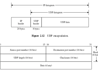
• Type of service (TOS, 8 bits): This eight-bit field specifies how the datagram should be handled by the routers. This TOS field is divided into two subfields: precedence (3 bits) and TOS (5 bits) as shown in Figure 2.2.Precedenceis a three-bit subfield with values ranging from 0 (000 in binary, normal precedence) to 7 (111 in binary, network control), allowing senders to indicate the importance of each datagram. Precedence defines the priority of the datagram in issues such as congestion. If a router is congested and needs to discard some datagrams, those datagrams with lowest precedence are discarded first. A datagram in the Internet used for network management is much more important than a datagram used for sending optional information to a group of users. Many routers use a precedence value of 6 or 7 for routing traffic to make it possible for routers to exchange routing information even when networks are congested. At
Precedence
(3 bits) D T R C
unused (1 bit)
0 1 2 3 4 5 6 7
TOS (4 bits)
D : Minimise delay (1000) T : Maximise throughput (0100)
R : Maximise reliability (0010) C : Minimise cost (0001)
present, the precedence subfield is not used in version 4, but it is expected to be functional in future versions.
The TOS field is a five-bit subfield, each bit having a special meaning. Bits D, T, R and C specify the type of transport desired for the datagram. When they are set, the D bit requests low delay, the T bit requests high throughput, the R bit requests high reliability and the C bit requires low cost. Of course, it may not be possible for the Internet to guarantee the type of transport requested. Therefore, the transport request may be thought of as a hint to the routing algorithms, not as a demand. Datagrams carrying keystrokes from a user to a remote computer could set the D bit to request that they be delivered as quickly as possible, while datagrams carrying a bulk file transfer could have the T bit set requesting that they travel across the high-capacity path.
Although a bit in TOS bits can be either 0 or 1, only one bit can have the value 1 in each datagram. The bit patterns and their descriptions are given in Table 2.1.
In the late 1990s, the IETF redefined the meaning of the eight-bit service type field to accommodate a set of differentiated services (DS). The DS defines that the first six bits comprise a codepoint and the last two bits are left unused. A codepoint value maps to an underlying service through an array of pointers. Although it is possible to design 64 separate services, designers suggest that a given router will only have a few services, and multiple codepoints will map to each service. When the last three bits of the codepoint field contains zero, the precedence bits define eight broad classes of service that adhere to the same guidelines as the original definition. When the last three bits are zero, the router must map a codepoint with precedence 6 or 7 into the higher-priority class and other codepoint values into the lower priority class.
• Overall length (16 bits): The IPv4 datagram format allots 16 bits to the total length field, limiting the datagram to at most 65 535 bytes. This 16-bit field defines the total length (header plus data) of the IP datagram in bytes. To find the data length coming from the upper layer, subtract the header length from the total length. Since the field length is 16 bits, the total length of the IP datagram is limited to 216−1= 65 535bytes, of which 20 to 60 bytes are the header and the rest are data from the upper layer. In practice, some physical networks are unable to encapsulate a datagram of 65 535 bytes in the process of fragmentation.
[image:39.476.170.308.527.608.2]• Identification (ID, 16 bits): This 16-bit field specifies to identify a datagram originating from the source host. The ID field is used to help a destination host to reassemble a fragmented packet. It is set by the sender and uniquely identifies a specific IP datagram sent by a source host. The combination of the identification and source
Table 2.1 Type of service (TOS)
TOS bit Description