i
DESIGN LOW NOISE AMPLIFIER WITH ULTRAWIDEBAND FREQUENCY
AHMAD HIEDZUANUDDIN BIN AHMAD KHIDIR
This Report Is Submitted In Partial Fulfillment Of Requirements For The Bachelor Degree of Electronic Engineering (Telecommunication Electronic) with Honors
Faculty Of Electronic Engineering and Computer Engineering Universiti Teknikal Malaysia Melaka
ii
UNIVERSTI TEKNIKAL MALAYSIA MELAKA
FAKULTI KEJURUTERAAN ELEKTRONIK DAN KEJURUTERAAN KOMPUTER BORANG PENGESAHAN STATUS LAPORAN
PROJEK SARJANA MUDA II
Tajuk Projek : DESIGN LOW NOISE AMPLIFIER WITH ULTRAWIDEBAND FREQUENCY 1GHz-5GHz Sesi
Pengajian : 1 1 / 1 2
Saya AHMAD HIEDZUANUDDIN BIN AHMAD KHIDIR mengaku membenarkan Laporan Projek Sarjana Muda ini disimpan di Perpustakaan dengan syarat-syarat kegunaan seperti berikut:
1. Laporan adalah hakmilik Universiti Teknikal Malaysia Melaka.
2. Perpustakaan dibenarkan membuat salinan untuk tujuan pengajian sahaja.
3. Perpustakaan dibenarkan membuat salinan laporan ini sebagai bahan pertukaran antara institusi pengajian tinggi.
4. Sila tandakan ( √ ) :
SULIT* *(Mengandungi maklumat yang berdarjah keselamatan atau kepentingan Malaysia seperti yang termaktub di dalam AKTA RAHSIA RASMI 1972)
TERHAD** **(Mengandungi maklumat terhad yang telah ditentukan oleh organisasi/badan di mana penyelidikan dijalankan)
TIDAK TERHAD
Disahkan oleh:
__________________________ ___________________________________ (TANDATANGAN PENULIS) (COP DAN TANDATANGAN PENYELIA)
iii
“I hereby declare that I have read this report and in my opinion this report is sufficient in terms of the scope and quality for the award of Bachelor of Electronic
Engineering (Telecommunication Electronic) with Honors”
Signature ::………
iv
“I hereby declare that I have read this report and in my opinion this report is sufficient in terms of the scope and quality for the award of Bachelor of Electronic
Engineering (Telecommunication Electronic) with Honors”
Signature ::………
v
For the most beloved and supporting parents,
AHMAD KHIDIR BIN MUIN DALILAH BINTI MUHD SAID
Special dedicated to my beloved parents, umi and ayah, beloved siblings,
vi
ACKNOWLEDGEMENT
With God’s grace, I have completed my final year project. I would like to thank all those who are involved in helping me to complete this project,
I would like to thank to En Mohammad Harris Bin Misran for being the source of inspiration and for the advices and assist that helped me in completing this project.
vii
ABSTRACT
viii
ABSTRAK
Dalam era teknologi komunikasi, ‘Ultrawideband’ adalah satu kaedah kemunikasi yang digunakan dalam rangkaian wayarles untuk mencapai sambungan jalur lebar dengan penggunaan kuasa yang rendah. Pada bahagian penerima system jalur ‘ultrawideband’ terdapat satu jenis khas penguat elektronik yang digunakan dalam system komunikasi yang menguatkan isyarat yang lemah dimana ia di diterima pada bahagian antenna. Ini sebahagiannya dipanggil penguat bunyi yang rendah dimana terletak akhir dihadapan penerima. Tanapa penguat lemah ini, ia akan menghasilkan isyarat yang lemah dan hingar. Suruhanjaya Komunikasi Persekutuan(FCC) telah memberi perlesenan ke atas penggunaan frekuensi
‘Ultrawideband’ yang terdiri daripada 3.1GHz ke 10.6GHz. Objektif projek ini
ix
TABLES OF CONTENTS
CHAPTER TITLE PAGE
ACKNOWLEDGEMENT vi
ABSTRACT vii
ABSTRAK viii
TABLES OF CONTENTS ix
LIST OF FIGURE xii
LIST OF TABLES xiv
LIST OF ABBREVIATIONS xv
LIST OF SYMBOLS xvi
LIST OF APPENDICES xvii
I INTRODUCTION 1.1 Project Background 1
1.2 Problem Statement 3
1.3 Objectives of Project 3
1.4 Scope of Project 5
1.5 Thesis Outline 5
II LITERATURE REVIEW
2.1 Ultra Wideband 5
2.2 Advantages and Limitation of the UWB 6 2.3 Comparison Ultra wideband, IEEE 802.11a
and Bluetooth 6
2.4 Ultra Wideband Works 7
2.5 Ultra Wideband Applications 8
2.6 Different Between Ultra Wideband
x
2.7 Difference between RF Power Amplifier
and Low Noise Amplifier 9
2.7.1 Power Amplifier 9
2.7.2 Low Noise Amplifier 10
2.8 CMOS versus PHEMT 10
2.9 HBT Technology 11
2.10 History of SiGe Technology 12
2.11 HBT Operation 14
2.12 Advantages of HBT 15
III METHODOLOGY
3.1 Introduction 16
3.2 Design Specification 18
3.3 Project Planning 18
3.4 Designs for Low Noise Amplifier 19
3.4.1 Bias Circuit (Self-Bias) 19
3.4.1 S-Parameter 20
3.4.2 Two Port Reflection Coefficient 22
3.4.3 Stability Consideration 23
3.4.4 Noise Figure 26
3.4.5 Input and Output Impedance matching 27
3.4.6 Stub Matching 29
3.4.7 The Quarter-Wave Transformer 30
3.5 Broadband Amplifier Design 31
3.5.1 Feedback Method 31
IV RESULTS AND ANALYSIS
4.1 Results 33
4.2 Stability 35
4.3 Matching network 38
4.4 Optimization 42
4.5 Hardware 45
xi
5.1 Conclusion and Future Works 49
xii
LIST OF FIGURE
NO TITLE PAGE
1.0 Wireless Communication 1
1.1 UWB Spectrum 3
2.1 Spatial capacity comparison between IEEE 802.11, Bluetooth 8
2.2 Operation of HBT 15
3.1 Flow Chart of Project 17
3.2 Gantt Chart 19
3.3 Transistor amplifier with self-bias 20
3.4 Incident and reflected waves Two Port Network 21
3.5 Signal flow graph of a two port network 21
3.6 Two Port Reflection Coefficient 22
3.7 Stability of two port 24
3.8 Smith Chart illustration for stable and unstable region for conditionally stable in the ΓS plane. a) |S22| < 1 b) |S22| >1 25
3.9 Smith Chart illustration for stable and unstable region for conditionally stable in the ΓL plane. a) |S11| < 1 b) |S11| >1 26
3.10 Input Output Matching Network 28
3.11 Single-stub tuning circuits. (a) Series Stub. (b) Shunt Stub 29
3.12 Quarter-Wave Transformer 30
3.13 Topologies of feedback amplifier(a) Voltage-sampling Series Mixing (series-shunt) topology, (b) Current-sampling shun -mixing(shunt series) topology, (c) Current-sampling series-mixing (series-series) topology, (d)Voltage-sampling shunt-mixing (shunt-shunt) topology 32
xiii
4.2 Biasing Circuit with RLC feedback 34
4.3 Stability and Noise Figure 35
4.4 Input Matching 39
4.5 Output Matching 40
4.6 Schematic Circuit of LNA 41
4.7 S11 and S22 42
4.8 Stability and Noise Figure 42
4.9 S12 and S21 43
4.10 Layout of LNA 44
xiv
LIST OF TABLES
NO TITLE PAGE
2.1 Comparison between Bluetooth, IEEE 802.11a and UWB 8
2.2 CMOS versus PHEMT 11
3.1 Design Specification 18
4.0 S Parameter at 3GHz 36
4.1 Comparison Simulation and Calculation 37
4.2 Input Matching Impedance 38
4.3 Output Matching Impedance 39
xv
LIST OF ABBREVIATIONS
ADS - Advance Design System
CMOS - Complementary-Symmetry Metal–Oxide–Semiconductor FCC - Federal Communication Commission
GPS - Global Positioning Systems LNA - Low Noise Amplifier LAN - Local Area Network
PHEMT - Pseudo orphic High Electron Mobility Transistors
RF - Radio Frequency
SS - Spread Spectrum
UWB - Ultra Wideband VLF - Very Low Frequency
xvi
LIST OF SYMBOLS
Symbols Definition
C Capacitor
dB Decibel
f Frequency
g Element Values
G Giga
H Height
Hz Hertz
I Current
K Rollet‟s Stability Factor
Km Kilometer
L Inductance
M Meter
mA Miliampere
mm Milimeter
mW Miliwatt
π
PiP Power
R Resistance
S Scattering
V Voltage
xvii
APPENDIX
APPENDIX TITLE PAGE
1
CHAPTER 1
INTRODUCTION
1.1 Project Background
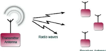
[image:18.596.217.421.611.710.2]Wireless communication is among technology’s biggest contributions to mankind. Wireless communication involves the transmission of information over a distance without using of wires, cables or any other forms of electrical conductors. The transmitted distance can be anywhere between a few meters (for example, a television’s remote control), it can transmitted distance anywhere with a thousands of kilometers (for example, radio communication). Actually, Ultra Wideband (UWB) wireless communications is a different approach and offers wireless communications compared to conventional narrow band systems. Global interest in the technology is huge. Some estimates predict the UWB market will be larger than the existing wireless LAN and Bluetooth markets.
2
Ultra-wideband (UWB) technology offers a solution for the bandwidth, cost, power consumption, and physical size requirements of next-generation consumer electronic devices. With the consistent high data rates across multiple devices and PCs within the digital home and office which enables wireless connectivity for UWB. This emerging technology provides the high bandwidth that multiple digital video and audio streams require throughout the home. With the support of industry workgroups, such as the wireless universal serial bus (USB) workgroup and technology leader’s example Intel technology there are offers to make a high speed WPAN which can connect the devices throughout the home.
At the receiver there are have an LNA design presents a considerable challenge because of its simultaneous requirement for high gain, low noise figure, good input and output matching and unconditional stability at the lowest possible current draw from the amplifier. UWB communication poses big challenges for low noise amplifier (LNA) design.
The design of LNA 1GHz until 5GHz is using BFP640 SiGe HBTr. Due to the designs that have chosen because designs for use in low cost commercial. It has high gain, high linearity and low noise performance and so on, so that it can satisfy our requirement perfectly in awide band range., Others the design will perform in FR3 board which have a fully intergrated for low noise amplifier for UWB.
3
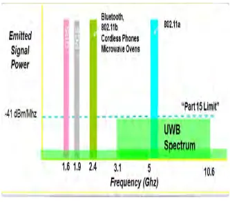
Figure 1.1 : UWB Spectrum
1.2 Problem Statement
LNA function in today’s communication system provides first level of amplification of the signal received at the receiver. The smallest possible signal that can be received by the receiver defines as receiver’s sensitivity.
The LNA function plays an undisputed importance in the receiver design. Its main function is to amplify extremely low signals without adding noise. thus preserving required signal to noise ratio of the system at extremely low power levels.
1.3 Objective
4
the signal is transmitted without contributing too much noise. The objective of this research is to perform circuit design, including circuit analysis such as simulation and measurement at 1GHz until 4 GHz frequency. This low noise amplifier will produce noise figure less than 1.5dB and also high gain above 12dB. The method used in obtaining the gain and noise figure is a feedback method,. The results of gain and noise figure from the three methods will choose the best result.
1.4 Scope of Project
The scope of works for this final year is to design a Low Noise Amplifier for Ultra wideband application. Following is the scope of project;
a) Literature Review – At the beginning of this project will be research on the theory such as circuit theory.
b) Calculation – Analysis can be doing by calculation in term of stability, gain. c) Simulation – Simulation is the procees that we have done for calculation part. d) Fabrication – After running the simulation part, the circuit can be design The
fabrication will be done using microstrip. The design will be fabricate the best technique
1.5 Thesis Outline
In this thesis outline there will be covered in four chapters. Chapter 1 is for Introduction. For this chapter, there are covers the background of the project, problem statement and scope of work in term of planning schedule.
5
CHAPTER 2
LITERATURE REVIEW
2.1 Ultra Wideband
In the technology of Ultra wideband for Radio Frequency which are using low energy to transmit binary data and extremely short duration impulses or bursts over a wide spectrum of frequencies. There are using over the distance from short to medium range 15 to 100 meters to deliver the data and also not involve a dedicated radio frequency. It’s known as a carrier-free, impulse and base-band radio.
Ultra-Wideband (UWB) is a high data rate, low power short-range wireless technology that is generating a lot of interest in the research community and the industry, as a high-speed alternative to existing wireless technologies such as IEEE 802.11 WLAN, HomeRF, and Hiper LANs. The main advantage of UWB technology is low cost transceiver design. The major challenges in Ultra Wideband Communication Receivers are high speed, high dynamic range of ADC and Wideband Low Noise amplifier.[1] Ultra-Wideband (UWB) technology is loosely defined as any wireless transmission scheme that occupies a bandwidth of more than 25% of a center frequency, or more than 1.5GHz [2].
6
was applied to impulse radars in military applications and this technology was restricted to military from 1960s to 1990s. However, ultra-wideband is now ready for commercial applications because of recent advancements in microprocessors stemming from the rapid development of semiconductor technology. Therefore, it is more appropriate to consider UWB as a new name for a long-existing technology. [3]
2.2 Advantages and Limitation of the UWB
There are many advantages in this UWB technology. The advantages of the UWB system are offers a high data transmission especially. Other’s than that the technology is the simple transceiver architecture. Ultra wideband also performs with the large channel capacity and high performance in multipath channels, and low signal-to-noise ratio and low power. UWB have been known as a power spectral
density which also allows them to coexist the in term of cellular systems, wireless local area network (WLAN) and Global Positioning Systems (GPS). The FCC power spectral density emission limit for UWB emitters operating in the UWB band is -41.3dBm/MHz. The Federal Communications regulates interstate and international communications by radio, television, wire, satellite and cable in all 50 states, the District of Columbia and U.S. territories
2.3 Comparison Ultra wideband, IEEE 802.11a and Bluetooth
7
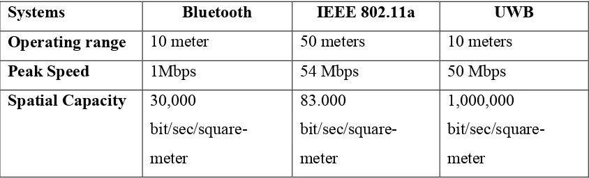
Table 2.1 : Comparison between Bluetooth, IEEE 802.11a and UWB
Systems Bluetooth IEEE 802.11a UWB
Operating range 10 meter 50 meters 10 meters
Peak Speed 1Mbps 54 Mbps 50 Mbps
Spatial Capacity 30,000
bit/sec/square-meter 83.000 bit/sec/square-meter 1,000,000 bit/sec/square-meter
2.4 Ultra Wideband Works