UNIVERSITI TEKNIKAL MALAYSIA MELAKA
DESIGN AND DEVELOPMENT OF AUTOMATED COUNTING
MACHINE FOR INDUSTRIAL APPLICATION
This report submitted in accordance with requirement of the Universiti Teknikal
Malaysia Melaka (UTeM) for the Bachelor Degree of Manufacturing Engineering
(Robotic and Automation) with Honours.
by
MUHAMMAD FARIS B MD YUSUF
FACULTY OF MANUFACTURING ENGINEERING
ABSTRACT
This project describes and reviews various sensor technologies, particularly through
beam sensor and retro reflective sensor, which is applicable to counting an object in
industrial applications. Aspects of review include technical requirement, design and
fabrication, and instrumentation procedures for the sensors. A comparative between two
sensors on the relative merit and selection criteria is carried out through an analysis of
advantage and disadvantage on real applications of sensors in counting method. Hence, a
details drawing for each part components were prepared and will be check to fabricate
and develop. Electrical component to control a machine were determined with its
function. Some of analysis will be taken as consideration to achieve a target objective of
ABSTRAK
DEDICATION
Special Dedicated to My Beloved Family
Md Yusuf Mahmud
Jawizah Mamat
Yusrizan Md Yusuf
Nor Fathilah Md Yusuf
Khairul Azli Md Yusuf
Al-Yani Md Yusuf
Nur Ashikin Md Yusuf
Ahmad Mokhzani Md Yusuf
Muhammad Asraf Md Yusuf
And
ACKNOWLEDGEMENT
I wish to thank my supervisor, Mr. Lokman Abdullah for his valuable advice,
constructive criticisms, stimulating discussions and valuable suggestions during the
preparation of this project report. I would like to express my thanks to all colleagues
who are always ready to give their helping hands. Last but not least, no words can be
used to express my deepest gratitude to my parent and family for their encouragement
TABLE OF CONTENT
Abstract i
Abstrak ii
Dedication iii
Acknowledgement iv
Table of Content v
List of Tables ix
List of Figures x
1. INTRODUCTION 1
1.1 Background Study 1
1.2 Problem Statement 2
1.3 Objective of Project 3
1.4 Scope of Project 3
2. LITERATURE REVIEW 4
2.1 Historical Development of Counting Machine
For Industrial Application 4
2.1.1 What is counting? 4
2.1.2 Historical counting device 4
2.1.3 Historical counting machine 5
2.1.3.1 Cremer Company 5
2.1.3.2 Cremer’s Method 6
2.2 Feeder Mechanism in Counting Machine 7
2.2.1 Type of Feeder Mechanism 7
2.3 Counter Detector in Counting Machine 11
2.3.1 Photoelectric Sensor 11
2.3.2 Principle of Photoelectric Sensor 12
2.3.3 Detection Object by Using Photoelectric Sensor 15
2.4 General Counting Machine 17
2.4.2 Discrete Tablet Counting Machine 18
2.4.3 Counting Method in a Leaves Counting Machine 19
2.4.4 Apparatus and Method for Counting Fruits and Other Object 22
2.5 Counting by using Programmable Logic Circuit 21
3. METHODOLOGY 22
3.1 Description Project Procedure 24
3.2 Counting Method Process 25
3.2.1 Description of Counting Method Process 26
3.3 Application Automated Counter by OMRON Industrial Automation 27
3.3.1 Step for Counting Procedure 28
3.3.2 Description of the Timing Chart 29
3.4 Design Detail of Photoelectric Sensor 30
3.4.1 Technique Used in Photoelectric Sensor 31
3.4.1.1 Through Beam Sensor 31
3.4.1.2 Sensing Method of through Beam Sensor 31
3.4.2 Retro Reflective Sensor 32
3.4.2.1 Retro Reflective Sensor Method 32
3.4.2.2 Retro-reflective Sensors with Polarization Filter 33
3.4.2.3 Limited-reflective Sensors 33
3.4.3 Advantages and Disadvantage Type Sensor 34
3.4.3.1 Through Beam Sensor 34
3.4.3.2 Retro Reflective Sensor 35
3.4.4 Comparison between Through Beam Sensor and
Retro Reflective Sensor 35
4. DESIGN AND DEVELOPMENT PLANNING COUNTING
DEVICE 39
4.1 Design Procedure 39
4.2 Working Process Counting Device 40
4.3 Simulation of Working Process 41
4.4 Process Sequence of Simulation 42
4.5 An Electrical of Hardwiring Process 43
4.6 Development Counting Device Planning 44
4.6.1 Description Development Procedure. 45
5. DESIGN AND DEVELOPMENT OF AUTOMATED
COUNTING MACHINE 46
5.1
Design of Automated Counting Machine Component by Using
Solid Work 46
5.1.1 Design a Component of Automated Counting Machine 46
5.1.2 Step of Designing of Automated Counting Machine 47
5.2 Automated Counting Machine Circuit 52
5.2.1 Component Electrical of Automated Counting System 52
5.3 Development Process of Automated Counting Machine System 55
5.3.1 Developing conveyor 56
5.3.1.1 Part of conveyor 56
5.3.2 Control panel 57
5.3.2.1 Step developing control panel 58
5.3.3 Laser beam 59
5.3.4 Sensor Receiver 59
6. RESULT 60
6.1 Result of Development Automated Counting Machine System 60
6.2 Automated Counting Machine Testing 61
6.2.1 Manually Counting Testing 61
6.2.2 Automatically Counting Testing 64
7. DISCUSSION 69
7.1 Discussion of Automated Counting Machine 69
7.2 Analysis of Counting Machine 72
7.3 Limitation of Counting Machine 78
8. CONCLUSION 79
8.1 Summary of Project 79
8.2 Conclusion 80
8.3 Recommendations 80
REFERENCES 81
APPENDICIES
LIST OF TABLES
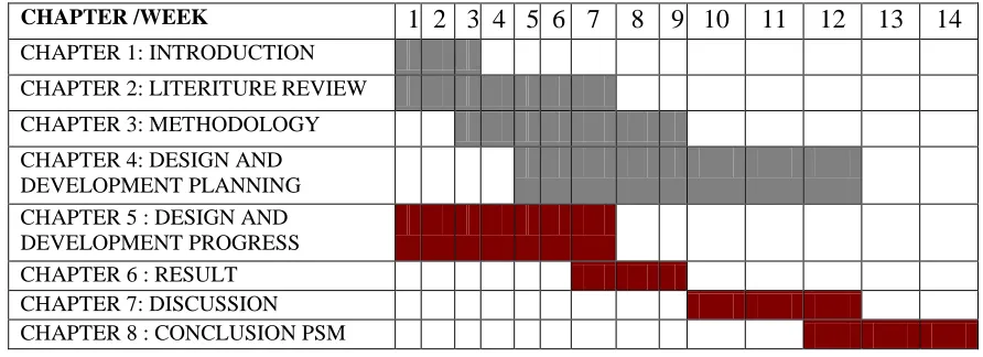
1.1 Gantt Chart of PSM 3
3.1 Advantages and Disadvantages of Through Beam Sensors 34
3.2 Advantages and Disadvantages Retro Reflective of Sensors 34
3.3 Comparison between Sensors 35
7.1 Comparison between Manually and Automatically Counting Operation 69
7.2 Counting Time for One Object for Variable
Width Size of Object 74
7.3 Sample with Different Width Size Object 75
7.4 Time Taken to Count with Different Width 75
7.5 Time Cycle for Five Objects 75
7.6 Object Sensed by Sensor Detector 76
LIST OF FIGURES
2.1 A Roman Abacus 5
2.2 First Counting Machine 6
2.3 Cremer’s Counting Principle 6
2.4 Tumbling Barrel Hopper 7
2.5 Bladed Wheel Hopper and Tumbling Barrel Hopper for Feeding of
Durable Cylindrical Parts 7
2.6 Rotating Drum for Orientating Plastic Bottles 8
2.7 Rotary Centerboard Hopper 9
2.8 Feeding of bottle caps in correct orientation. 9
2.9 Creating a single file of washer in a vibratory. 10
2.10 Orientating Headed Screws or Rivets at the Top Discharge
Potion of Vibratory Bowl 10
2.11 Through-beam Sensor 11
2.12 Retro-reflective Sensors 11
2.13 Diffuse-reflective Sensors 12
2.14 Mode Reflectivity Table 13
2.15 Diffused Mode with Mechanical Background Suppression. 13
2.16 Diffused Mode with Electronic Background Suppression. 14
2.17 Variation the Bottle Moves Through The Light Beam. 17
3.1 Summary of Project Procedure 23
3.2 Count Method on Counting Machine 26
3.3 Counter Automated in Production Line 27
3.4 The Input, Control and Output Signal Sequence in a Boxing Process 27
3.5 Input Signal 28
3.9 Photoelectric Counter 31
3.10 Sensing Method Through Beam Sensor 32
3.11 Retro Reflective Sensor 32
3.12 Retro-reflective Sensors with Polarization Filter 33
3.13 Sensing Method Reflective Sensors 34
3.14 Structure of a Typical Counter 37
3.15 The Effective Beam of Opposed-Mode Sensors 37
4.1 Step in Design Procedure 39
4.2 Flow Chart Working Process 40
4.3 Electrical Circuit by Using Automation Studio 41
4.4 Hardwiring Process 43
4.5 Development Procedure 44
5.1 Process designing automated counting machine 47
5.2 Shaft’s Conveyor 47
5.3 Conveyor Body 48
5.4 Stand Conveyor 48
5.5 Belt Conveyor 48
5.6 Assembly Component of Conveyor 49
5.7 Box 49
5.8 Digital Counter 49
5.9 Push Button 50
5.10 Indicator light 50
5.11 Control Panel. 50
5.12 Laser Beam 51
5.13 Sensor Receiver 51
5.14 Base 51
5.15 Automated Counting Machine 52
5.16 Schematic Motor Conveyor 54
5.18 Sensor Receiver Circuit 55
5.19 Shaft 57
5.20 Electrical motor 57
5.21 Bearing 57
5.22 Front View Conveyor 57
5.23 Side View Conveyor 57
5.24 Internal View of Control Panel Box 58
5.25 Connector on Control Panel Box 58
5.26 Internal Laser Beam 59
5.27 Laser Beam Position on Conveyor 59
5.28 Sensor Receiver 59
5.29 Sensor Receiver Position 59
6.1 Automated Counting Machine 60
6.2 Flow process manual counting testing 62
6.3 Presspush button on orange indicator 63
6.4 Digital counter display 63
6.5 Push button on red indicator 63
6.6 Flow Process of Automatic Counting Testing 65
6.7 Switch Power 67
6.8 The “Dark ON” Operation 67
6.9 Sensor Cannot Receive a Light Beam 68
6.10 Orange Indicator Blinking 68
6.11 Count Up 68
6.12 Count on Preset Value 68
6.13 Red Light 68
7.1 Object Position before Count 70
7.5 Angle of Light Beam to Sensor Receiver 73
7.6 Width Size of Object. 73
7.7 Graph Time Taken for One Object 74
7.8 Graph Time Versus with Width Object 75
CHAPTER 1
INTRODUCTION
1.1 Background Study
Development of counting machine in industrial application has been chosen to fulfill PO
and PEO in course Manufacturing Robotic and Automation. Nowadays, there’s much
manufacturing of machine in engineering field. The method and results of measuring the
accuracy of a particle sizing and counting machine are described and compared with the
results obtained when sizing with a microscope. Machine counting appears to be quicker
and more consistent and accurate than counting by eye (Courshee, R. J. 1954).
A counting machine consists of feeding system in electrical and electronic component.
For an example is vibratory bowl where it’s the oldest method and still most common
approach to the automated feeding (orienting) of industrial parts. Part feeders, which
singulate and orient parts prior to packing and insertion are critical components of an
automated assembly line. The oldest and still most common approach to automated
feeding is the vibratory bowl feeder which consists of a bowl filled with parts
surrounded by a helical metal track. An application of vibratory bowls are suitable for
feeding components for subsequent operations on special machines in cosmetic,
electrical, mechanical, pharmaceutical, optical, bearing and many other industries. The
Sensing methods based on electrical capacitance, magnetic and eddy-current effects are
extremely sensitive and fasting acting and are suitable in close proximity to the sensor.
The capacitive probe senses dielectric other than air, such as glass and plastic parts. The
magnetic pickup by induction responds to the motion of iron and nickel. The
eddy-current sensor, by energy absorption detected nonmagnetic conductors. All are suitable
for counting machine operations.
1.2 Problem Statement
The development of the counter sensor technologies makes the choice of sensor in
market higher. It sometime makes the engineer difficult to make the decision making in
other to choose the best sensor that suitable for the counting part. Sometimes wrong
decision will make the thing even worse. So that, this research is developed to identify
the technology itself, technical requirement, and instrumentation and make the engineer
or other bodies that involves can compare the differential between many types of sensor
and make them can used it in correct condition.
Error-proofing is an industry term that relates to the implementation of mechanisms to
prevent product defects. Also known as Poka Yoke from the Japanese ‘poke’ (inadvertent errors) and ‘yoke’ (to avoid), error-proofing is a common-sense concept
developed and popularized in that country. Based on the philosophy, even the smallest
number of defects is unacceptable. Poka Yoke maintains that the best way to eliminate
defects is to prevent them from happening in the first place. Awareness involves the
acknowledgement of breakdowns in the manufacturing/assembly process and employing
training, audio-visual aids and general assistance for personnel to combat those issues.
Detection introduces manual or automated inspection techniques to filter out defects.
Prevention which includes process improvements or automation to ensure no errors are
The primary issues are limited range and sensitivity to sensors. There need to increase
the sensing range, reduce cost, and expand capabilities led to the development of
photoelectric sensors optimized for detecting clear objects. Initially, ultrasonic sensors
were more dependable and accurate at identifying targets, but over the last few year
improvements in photoelectric sensors have made them the primary choice for sensing
clear objects (better edge detection, increased resolution, indifference to size, shape, or
temperature of target).
1.3 Objective of Project
Objectives that have to be achieved at the end of this project are design and development
of an automated counting machine.
1.4 Scope of Project
The scope should be identified and planned to achieve the objectives of the project
successfully on the time. Scope of this project is concentrate on how a counting device
works for count an object or particle. Hence, analyses on automated counting machine
[image:21.612.102.548.523.685.2]such as test and accuracy of counting device to count an object.
Table 1.1: Gantt chart of PSM.
CHAPTER /WEEK 1 2 3 4 5 6 7 8 9 10 11 12 13 14
CHAPTER 1: INTRODUCTION CHAPTER 2: LITERITURE REVIEW CHAPTER 3: METHODOLOGY CHAPTER 4: DESIGN AND
DEVELOPMENT PLANNING
CHAPTER 5 : DESIGN AND
DEVELOPMENT PROGRESS
CHAPTER 6 : RESULT
CHAPTER 2
LITERATURE REVIEW
2.1 Historical Development of Counting Machine For Industrial
Application
2.1.1 What is counting?
From Wikipedia Encyclopedia, count is a mathematical process for an object where it as
be set aside with desired of number objects to repeatedly action to adding or subtracting.
Hence, counting also can be involved more than one for example; counting by a two (2,
4, 6, 8….). From the archeological, they have found that a counting has been used last
500,000 year.
2.1.2 Historical Counting Device
On 500 B.C to 1300A.C, Babylon culture is the one who made up a first counting device
called Abacus. The Abacus is used to calculate an arithmetic process and it’s also act as
a calculating tool on that time. After hundreds year, a counting board have been develop
Figure 2.1: A Roman Abacus (Illustrated from Wikipedia Encyclopedia).
2.1.3 Historical counting machine
2.1.3.1 Cremer Company
On 1949, Cremer Company has built up a counting machine in packaging and counting
line logistics. This company preferred supplier for counting machine and packaging
solution on pharmacy, confectionery, bakery and frozen foods, packed snack food,
hardware, medical supplies, flower bulbs, etc. A customer of this company in this world
wide used counting and packaging machine are Nestle, Cadbury, Frito Lay, Kraft Foods,
Glaxo, General Mills, Masterfoods, ConAgra, Chupa Chups, De la Rosa, Sabritas,
Philips, Bayer, Wyeth Ayerst, Pfizer and Boehringer, Eli Lillyand and Dr. Oetker.
In 1982, Cremer introduced the first linear tablet and capsule counting machine. Ever
since, the CF model has been renowned worldwide for its 100% accuracy, high capacity,
simple cleaning and operation, high reliability and durability. The Cremer CF counting
machine is a high-speed tablet and capsule counting machine for pharmaceutical and
Figure 2.2: First counting machine (Illustrated from Cremer Company).
2.1.3.2 Cremer’s Method
A line principle is used on all counting machine in Cremer Vibratory plates to separation
of products before falling through detector channel. Cremer’s method on count products
is products are cascaded down through a Memory flap see Figure 2.3. Hence, the correct
quantity is discharged into a bucket elevator or packaging machine.
[image:24.612.203.471.460.648.2]