Int. J. Electrochem. Sci., 8 (2013) 6997 - 7003
International Journal of
ELECTROCHEMICAL
SCIENCE
www.electrochemsci.org
Technical Report
Calculations for Initial Design and for Failure Analysis of
Water-Electrolysis Based Hydrogen-Generating Systems
Zhou Junbo*, Zhang Xiang, He Hong
College of Mechanical and Electrical Engineering, Beijing University of Chemical Technology, 15, North Third Ring East Road, Chaoyang District, Beijing, 100029, PR China.
*
E-mail: [email protected]
Received: 28 February 2013 / Accepted: 31 March 2013 / Published: 1 May 2013
Hydrogen is widely used in the petroleum, chemical production, and military industries, and as a power source. One of the most important methods for generating hydrogen is by the electrolysis of water. This type of hydrogen- generating system is widely used in thermal power plants, nuclear power plants, and this type of system is used to feed oxygen in airtight spaces such as nuclear submarines and spacecraft. Here, we evaluated the essential flowchart of hydrogen production by water electrolysis. The pressures at several key points in the feed-water system were calculated, and the causes of the feed-water system failure were analyzed. The solutions to key problems with respect to system design and commissioning are presented.
Keywords: hydrogen-generating system, hydrogen, oxygen, feed water, failure analysis
1. INTRODUCTION
water electrolysis can be increased. Because there were serious energy inefficiency phenomena [12] in the peak periods of hydropower and wind-power generation, electricity substitution measures were taken between hydroelectric power and thermal power in Sichuan, China to reduce electricity losses. There were six-instances of such transactions in 1999 alone, and the amount of electricity that was provided by these substitute methods was up to 1.1234 billion kW h [13]. It is reported that at present, several power stations in China operate under capacity although they had an installed hydropower capacity of 70,000,000 kW at the end of the last century [14, 15]. Even after the Three Gorges Project is completed, energy loss due to abandoned water is expected to occur in dry years. According to the estimations of the Yangtze River water conservation, electrical energy losses from abandoned water reached 4.5 billion kW h. Even though a 1.8 million-kW pumped-storage power station was built to operate concurrently with Three Gorges hydropower station, the electrical energy loss from abandoned water in the Three Gorges hydropower station will amount to 2.1 billion kW h; this amount of water could be used to produce 0.4-0.45 billion Nm3 of hydrogen. In addition, wind energy up to 253 million kW [16] is available, and the installed wind power capacity reaches 230,000 kW in China. This kind of energy is variable and cannot be connected to the power-supply grid. However, wind is a very good alternative energy source for the production of hydrogen by water electrolysis, and the hydrogen can be stored and later converted into electrical energy when necessary. If the above-mentioned methods can be put into practice, hydrogen production from water electrolysis will have broad applications and it will be a strong competitor of other methods of hydrogen production.
More than one hundred sets of water-electrolysis hydrogen generators for power plants (made by the Handan Purification Equipment Research Institute, China) have been used in many regions of China; this equipment is used, for example, at the famous Qinshan nuclear power station, the Lianyun harbor nuclear power station, the Huaneng group power plant in Beijing, as well as at power plants in the southeast and northwest regions of China. Such equipment has also been exported to many countries, including Bangladesh, Iraq, India, South Korea and North Korea. Last year, in North Korea, the failure of a feed-water system occurred when we debugged the equipment. In order to solve this problem of the failure of the system due to the debugging, we analyzed the process flow of the equipment and the structural layout of the equipment, and we calculated the pressures at several key positions of the feed-water system. The cause of the failure was identified, and a solution was proposed.
2. BASIC TECHNOLOGICAL PROCESS AND FAILURE PHENOMENON
in the literature rarely; therefore, finding out the causes and solutions to this problem is necessary to the promotion of the application of water electrolysis hydrogen production.
We first analyzed the basic process flow for the hydrogen-generating system in order to determine the cause of failure in the feed-water system.
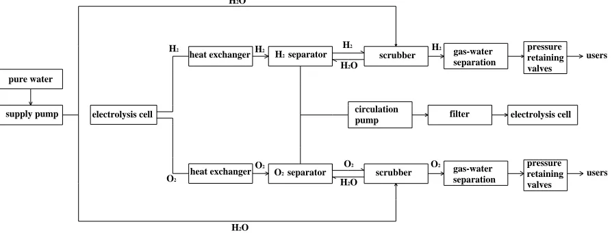
The failed system in North Korea was a ZDQ-type water-electrolysis hydrogen-generating system; an example process flow chart for this type of system is shown in Figure 1.
The hydrogen generation procedure is as follows: an NaOH/KOH solution is subjected to electrolysis that generates hydrogen gas at the cathode and oxygen gas at the anode. Next, the product mixtures enter the heat exchangers to be cooled, and then the mixtures are fed into a gas-liquid separator. After separation, the gases and liquid go through different routes: alkali ions in the gas phase are disposed of in the scrubber, then the other gases (hydrogen or oxygen) are filtered out using the gas-water separators; the liquid flows through the circulation pump and filter and then returns to the electrolysis cell from the bottom of the separators. The entire process is cyclic and it is repeated many times. In the electrolysis process, ideally, the alkali is not consumed, and only supplementation with pure water is needed. The pure water is added into the scrubber by the supply pump, and the water flows back to the separator to mix with the electrolyte; this is known as the feed-water system. In the debugging process, the failure phenomenon was found to be that the feed water can flow into the scrubber, but it cannot flow into the separators. Thus, to ensure the normal flow of gas, liquid and added water in the operation of the system, the two-phase flow problem between the scrubbers and the separators should be solved. In order to solve this problem, the pressures at some key points in the feed-water system were calculated.
pure water
supply pump electrolysis cell
H2 separator
O2 separator
scrubber
scrubber
gas-water separation
gas-water separation
pressure retaining valves
pressure retaining valves circulation
pump filter electrolysis cell
H2 H2 H2 H2
O2
O2 O2 O2
H2O
H2O
H2O
H2O
users
users heat exchanger
[image:3.596.77.524.436.606.2]heat exchanger
Figure 1. Flow chart of ZDQ water-electrolysis hydrogen-generating system.
3. THE DESIGN AND ANALYSIS OF THE PRESSURES AT KEY POINTS IN THE FEED-WATER SYSTEM
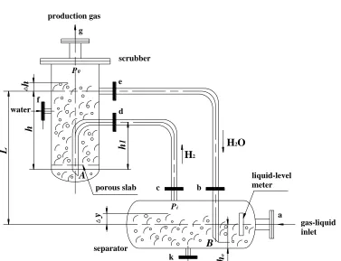
The gas and liquid pressure distributions during normal system operation at several key points (as outlined in Figure 2) were designated as follows[20, 21]:
A: the pressure-retaining valve is set at P0; that is, the scrubber outlet pressure is P0 B: the gas pressure in the upper part of the separator is Pi.
Then, the pressure at point A is
) (
g 1
0 h h
P
PA ρ (1),
and the pressure at Point B is )
( g 2
0 h y
P
PB ρ (2),
where ρ1 is the specific gravity of the solution in the scrubber and ρ2 is the specific gravity of
the solution in the separator.
To maintain normal operation of the system and keep the gas path unobstructed, the gas in the separator must flow into the scrubber along the pipeline from orifice c and come out of the scrubber from orifice A. After effervescence and water washing, the gas bubbles rise to the top of the scrubber and leave from orifice g. Thus, the following condition must be guaranteed:
i A
PP , that is to say, Pi P01g h( h) (3).
production gas
scrubber
e
f
d
c b
k separator
gas-liquid inlet porous slab
liquid-level meter H2
H2O
a water
g
L
h
h
P0
A
B
h
o
y Pi
h
[image:4.596.113.490.420.709.2]1
Moreover, the process should also ensure that the water in the scrubber can enter the separator from orifice e and exit at point B to mix with the alkaline solution and then flow out from orifice k. Afterward, the liquid is pumped back to the electrolytic cell by a circulation pump. If the system is working properly, then the following equation is true:
0 1 ( 0) B
P g h L h P (4).
Substituting Equation (2) into Equation (4), we obtain:
2 ( 0 ) 0 1 ( 0)
i
P g h y P g h L h (5).
When the system is in a stable equilibrium state, substituting Pi P01g h( h) into Equation (5) yields:
0 1 ( ) 2 ( 0 ) 0 1 ( 0)
P g h h g h y P g h L h (6).
Collating Equation (6) yields Equation (7):
1gL 1(h h0) 2g h( 0 y) ,
2 1( 0 ) 0
L h y h h (7).
According to Equation (7), we should select suitable geometric parameters in design, such as h, and h0,and the requirement of the following equation should be satisfied when we carry out through the design integration:
2 1( 0 ) 0
L h y h h (8).
In the above equation, yis the only variable, and the liquid level in the separator can be controlled to within the normal level only when the parameterysatisfies the requirement of | y |≤h0. Otherwise, whenyis positive andy>h0, the liquid level exceeds the upper control limit; whenyis negative and|y|>h0, orifice B will be out of the water and exposed to the gas phase. This causes the water in the vertical tube to flow quickly into the separator, and the gas will rise immediately from section b and then enter the scrubber through section e. Even if the water was supplied to the scrubber by a pump at this moment, the gas will take a short-cut and flow into the scrubber from section e, whereas the liquid can only flow out of the scrubber from section d to enter the separator through section c. In this case, the pressure at each point is given by the following equations:
0 1
i B
p P P g h (9),
0 1 ( )
A
The liquid pressure at section d isP01g(h h 1 h).
The gas pressure at section d is Pi. In order to ensure that the liquid flows out through section d, we should confirm that the conditions meet the following criterion:
0 1 ( 1 ) i
P gh h h P (11).
Because Pi only relates to the gas production in a working situation, Pi is not able to be adjusted. From Equation (11), we observe that only the magnitude of (h-h1) can be changed to enable
the water to flow out from section d and enter the separator through section c. Only when the difference (h-h1) is as large as possible while satisfying Equation (11) can the feed water continue to
enter the separator; this occurs until the water level exceeds the level of section b, and the gas pressure at the top of the separator increases until Pi>PA. Subsequently, gas-liquid exchange occurs once more and the system returns to normal operation.
4. CONCLUSIONS AND IMPROVEMENT MEASURES
4.1. Conclusions
From the above analysis, we know that the cause of the feed-water-system failure is that the orifice B was above the water. Two possible situations can cause this failure: one is when the liquid level of the separator is too low; the other is when the immersion length of standpipe inserted into the separator is too short (the distance h0 is too small). These can both be solved by improving the design.
4.2. Improvement measures
First, the immersion length of the standpipe should be extended to ensure that the value of h0 is greater than the lower line of the level gauge on the right side of the separator. Where existing equipment must be retrofitted and h0 is sufficiently large, the method of raising the lower-limit level in the separator can be used to solve the problem in situ in the case of automatic water feeding. In the case of a manual water feeding, the liquid level in the separator should be continuously monitored and water fed in periodically as necessary.
Second, the height of section d in the scrubber should be reduced, that is, the value of (h-h1)
should be increased. Only when orifice B is above the water, could the water flow back to the separator from section d automatically. A continuous system could be gradually adjusted to normal operation.
or started, the minimum automatic feed-water limit level must be set, and it should not be set too low. At the same time, it is better not to employ the manual feed-water mode. If the manual mode must be adopted, the liquid level in the separator must be higher than the minimum limit; that is to say whenyis negative and |y|≤h0.. So long as the above-mentioned principles are heeded with respect to design and debugging, feed-water failures can be eliminated and these types of systems will operate normally.
References
1. M.Ni, M.K.H.Leung, K.Sumathy, Energy Environmental Protection, 18(2004):5-9
2. Kaveh Mazloomi, Nasri b.Sulaiman and Hossein Moayedi, Int. J. Electrochem. Sci. , 7(2012) 3314-3326
3. Zhou Jie, Zheng Yingping and Xie Jihong, Chemical Industry Times, 5 (2007)71-74 4. S.Ahemed and M.Krumpelt, International Journal of Hydrogen Energy, 4 (2001)291-301
5. Yue Lei, Zhang Zhiguo and Peng Yaling,Journal of Ship Science and Technology, 2 (2009)63-65 6. Bonghwan Lee, Kiwon Park and Hyung-Man Kim, Int. J. Electrochem. Sci. , 8(2013) 235-248 7. Zeng Qingtang, Zheng Chuanxian, Space Medicine and Medical Engineering, 3 (1990)222-226 8. S.Srinivasan, F.J.Salzano, International Journal of Hydrogen Energy, 1 (1977)53-59
9. J. T. Larkins, et al, Static feed water electrolysis system for space station O2 and H2 generation,
Paper No: 851339, Intersocity Conference on Envieonmental System, (1985)
10.A.C. Erickson, et al, Space station life support oxygen generation by SPE Water electrolyzer system, SMA 86 0949
11.Kaveh Mazloomi, Nasri b.Sulaiman and Hossein Moayedi, Int. J. Electrochem. Sci. , 7(2012) 3466-3481
12.Xia Caiqing, International Journal of Hydroelectric Energy, 4 (2002)55-58 13.Fan Tianlong, Sichuan Water Power, 1 (2000) 57-67
14.Bing Fengshan, Journal of Hydroelectric Energy, 3 (1999)1-5
15.Gu Weidong, Yan Zhouyong, International Journal of Hydrogen Energy, 37(2012) 737-740 16.Chen Yongxiang, Journal of Energy Technology, 6 (2008)350-355
17.Xiu Kai, Wang Zhi, Bai Feng, Ship Science and Technology, 2(2006)99-101 18.Chen Shiying, Inner Mongolia Science Technology and Energy, 4(2012)93-94 19.Yan Youmin,Yu Xiao, Yan Zhanjiang, Desert and Oasis Meteorology,5(2011)59-62
20.Qi Rongbin, Liang Zhiguo, Journal of Petro-chemical equipment,30(supplement) (2001)24-26 21.Qi Deqing, Hydromechanics in projects, Shanghai: Tongji University Press (1995)