Rochester Institute of Technology
RIT Scholar Works
Theses
Thesis/Dissertation Collections
12-12-2016
Implementation of an Object-Oriented Life Cycle
Assessment Framework Using Functional Analysis
and Systems Engineering Principles
Shantanu Avinash Gadre
Follow this and additional works at:
http://scholarworks.rit.edu/theses
This Thesis is brought to you for free and open access by the Thesis/Dissertation Collections at RIT Scholar Works. It has been accepted for inclusion in Theses by an authorized administrator of RIT Scholar Works. For more information, please [email protected].
Recommended Citation
i
R
OCHESTERI
NSTITUTE OFT
ECHNOLOGYI
MPLEMENTATION OF ANO
BJECT-O
RIENTEDL
IFE CYCLE ASSESSMENTFRAMEWORK USING FUNCTIONAL ANALYSIS AND SYSTEMS ENGINEERING
PRINCIPLES
By
Shantanu Avinash Gadre
Submitted in Partial Fulfillment
of the Requirements for the Degree of
Master of Science in Industrial & Systems Engineering
in the
Department of Industrial and Systems Engineering
Kate Gleason College of Engineering
ii
DEPARTMENT OF INDUSTRIAL AND SYSTEMS ENGINEERING
KATE GLEASON COLLEGE OF ENGINEERING
ROCHESTER INSTITUTE OF TECHNOLOGY
ROCHESTER, NY
CERTIFICATE OF APPROVAL
M.S. DEGREE THESIS
The M.S. Degree thesis of Shantanu Avinash Gadre
has been examined and approved by the
thesis committee as satisfactory for the
thesis requirements for the
Master of Science degree
Approved by:
Dr. Marcos Esterman, Thesis Advisor
iii
A
CKNOWLEDGEMENTSThe development of this work would not have been possible without the continuous support and guidance of my primary thesis advisor Dr. Marcos Esterman. His teachings and beliefs have influenced my life even beyond the academic world. I am grateful to him for all the support.
I would also like to thank Dr. Brian Thorn for sharing his feedback and knowledge in the area of Life cycle assessment. I would like to acknowledge the Industrial & Systems Engineering department at RIT for granting me a scholarship to pursue Master’s degree. Without this, I would not have been able to obtain this specialization.
iv
ABSTRACT
v
Contents
ABSTRACT ... iv
Figures ... vi
Tables ... viii
1.0 Background ... 1
1.1 Life Cycle Assessment (LCA) ... 1
1.2 LCA in Product Development ... 4
2.0 Literature Review ... 6
2.1 CAD-PLM-LCA Integration Efforts ... 7
2.2 Functional Analysis in LCA ... 12
2.3 Modularity / Object Orientation and LCA ... 15
3.0 Problem statement definition ... 18
4.0 Methodology ... 19
4.1 Methodology STEP 1: Functional decomposition and identification of reference flows ... 19
4.2 Methodology STEP 2: Establish Use parameters, System parameters and Cumulative Damage Function (CDF) ... 27
4.3 Methodology STEP 3: Implementation using SimaPro ... 33
5.0 Case Study Implementation ... 42
5.1 The Keurig K 2.0 200 coffee brewing system- ... 43
5.2 Implementation of Methodology on Keurig System ... 46
5.2.1 STEP 1: Functional decomposition and identification of reference flows ... 46
5.2.2 STEP 2: Establish Use parameters, System parameters and Cumulative Damage Function (CDF) ... 63
5.2.3 STEP 3: Implementation using SimaPro ... 70
6.0 Results and Conclusion ... 84
7.0 Future Work ... 92
8.0 References ... 95
Appendix A ... 100
vi
Figures
Figure 1: Phases of Life Cycle Assessment (ISO. 2006) ... 2
Figure 2: PPR model - adapted from JP Theret, Evrard, and Mathieux (2011) ... 8
Figure 3: Physical Container Fuon (Adapted from Collado-Ruiz & Ostad-Ahmad-Ghorabi, 2010) ... 14
Figure 4: Generic LCA system framework (Esterman et al. 2012b), used with permission ... 15
Figure 5: Black Box model, adapted from (Otto & Wood, 1998) ... 20
Figure 6: Hierarchical functional decomposition, adapted from (Otto & Wood, 1998) ... 20
Figure 7: Black box model of a Printer ... 21
Figure 8: Black box model of Can Opener ... 22
Figure 9:Level 2 sub functions of Can Opener ... 23
Figure 10: Access can decomposition ... 23
Figure 11: Puncture can decomposition ... 23
Figure 12: Rotate Can decomposition ... 24
Figure 13: Butterfly Can opener ... 25
Figure 14: BOM-Can opener ... 26
Figure 15: Structure mapping -penetrate lid ... 27
Figure 16: Function- Structure diagram of Can opener ... 27
Figure 17: CDF allocation for Can opener ... 33
Figure 18: Can opener Function-Structure in SimaPro ... 34
Figure 19: Level 1 to Level 2 decomposition ... 34
Figure 20: Building Blocks in SimaPro ... 35
Figure 21: Rotate can implementation ... 35
Figure 22:Can opener Function-Structure in SimaPro ... 36
Figure 23: Use parameters for can opener in SimaPro ... 37
Figure 24: System parameters and CDF calculation for Puncture can ... 38
Figure 25: Entering CDF values for allocation ... 39
Figure 26: Environmental hotspot network for can opener ... 39
Figure 27: Environmental impacts of Puncture can & Rotate Can ... 40
Figure 28:Environmental impacts of Grip can edge & Penetrate Lid ... 40
Figure 29: Use parameter for Scenario S1 ... 41
Figure 30: System parameter and CDF for scenario S1 ... 41
Figure 31: Comparison of environmental impacts between two use scenarios ... 42
Figure 32: Keurig system overview (Keurig use & care guide K2.0 series, 2015) ... 44
Figure 33: Keurig schematic layout ... 44
Figure 34: Main function of a coffee machine ... 47
Figure 35: Decomposition of main function of coffee maker into Level 1 sub functions ... 48
Figure 36: Decomposition of Extract soluble into Level 2 sub functions ... 48
Figure 37: Decomposition of Prepare Water into Level three sub functions ... 49
Figure 38: Decomposition of Prepare S+C into Level three sub functions ... 50
Figure 39: Decomposition of Transfer Soluble to water into Level 3 sub functions ... 50
vii
Figure 41: Decomposition of Mix flavor with S+W into Level 2 sub functions ... 51
Figure 42: Decomposition of Communicate with user into Level 2 sub functions ... 52
Figure 43: Water reservoir assembly and filter assembly ... 53
Figure 44: K cup holder assembly ... 54
Figure 45: Top jaw and piercing needle frame ... 54
Figure 46: Bottom Jaw ... 55
Figure 47: Air Pack ... 55
Figure 48: Water Pack ... 56
Figure 49: Base and Enclosure... 56
Figure 50: Heater module ... 57
Figure 51: K cup (Keurig use & care manual k2.0 series, 2015) ... 57
Figure 52: Reversible Function- Insert/Remove K cup ... 59
Figure 53: Single component to single function mapping ... 60
Figure 54: Single function to multiple component mapping ... 61
Figure 55: Join top heater cover to bottom heater bowl mapping ... 61
Figure 56: Single component to multiple function mapping ... 61
Figure 57: Function to feature and component mapping ... 62
Figure 58: Mapping Tank & its features to functions ... 63
Figure 59: Coffee Brewing function ... 64
Figure 60: Decomposition of main function of coffee maker into Level 1 sub functions ... 66
Figure 61:CDF allocation for Extract Soluble ... 69
Figure 62: Function-Structure of Keurig in SimaPro ... 71
Figure 63: Decomposition of main function of coffee maker into Level 1 sub functions ... 71
Figure 64: Main function to Level 1 function for Keurig ... 72
Figure 65: Level 1 to Level 2 mapping for Keurig ... 73
Figure 66: Lowest level function to structure mapping for Keurig... 73
Figure 67: Definition of Nut in SimaPro ... 74
Figure 68: Lowest level function to structure mapping in SimaPro ... 74
Figure 69: Use parameters of Keurig in SimaPro ... 75
Figure 70: System parameters for Extract soluble ... 76
Figure 71:CDF allocation for Extract Soluble ... 76
Figure 72:Allocation for Prepare water function ... 77
Figure 73: Allocation 'Transport water for heating' ... 77
Figure 74: Life cycle of coffee machine ... 78
Figure 75: Sea route from Shenzhen to Port of New York ... 79
Figure 76: Transportation Scenario ... 79
Figure 77: Energy calculation for Heat Water ... 81
Figure 78: Energy Allocation for heater ... 81
Figure 79: Lifecycle network of coffee machine ... 82
Figure 80: Life cycle impacts coffee machine ... 82
viii
Figure 82: Eco points for Extract Soluble function ... 83
Figure 83: Heat Water module network ... 84
Figure 84: Coffee brewing ... 85
Figure 85: Scenario comparison ... 87
Figure 86: Scenario comparison -Prepare Water ... 87
Figure 87: Impact Network ... 89
Figure 88:Comparison Heat water solutions ... 89
Tables
Table 1: Use & System parameters of Can opener ... 29Table 2: Product selection criteria ... 43
Table 3: Derivation of use parameters from reference flows ... 64
Table 4: Average daily usage scenario for coffee machine (See below for a detailed description and references for the parameters) ... 65
1
1.0 Background
1.1 Life Cycle Assessment (LCA)
There has been a growing awareness about the environmental impacts of producing and consuming goods and services. Among the various tools that have been developed to better understand these impacts, Life Cycle Assessment (LCA) is one of the most commonly used tools to estimate the environmental effects of products and services (Walter Klöpffer 2014). LCA is a systematic way to account for and subsequently manage the environmental impacts associated with the entire life cycle of the system under consideration.
Life Cycle Assessment is defined by ISO 14040 (ISO. 2006) as “LCA studies the environmental aspects and potential impacts throughout a product’s life cycle (i.e. cradle to grave) from raw material
acquisition through production, use and disposal. The general categories of environmental impact
needing consideration include resource use, human health, and ecological consequences.” One of the important features of LCA is the capability to study the product throughout its entire life cycle. The ‘cradle to grave’ approach ensures that all the stages of a product’s life cycle are considered for assessing
its environmental impacts. A product’s life cycle is composed of different unit processes namely raw material extraction, production of intermediate products, production of end product, usage of product by a consumer and its disposal or/and recycling. Even the transportation across these phases is taken into account in an LCA study (Walter Klöpffer 2014).
An important concept used in LCA is the functional unit. The functional unit is defined by ISO as “the quantified performance of a product system for use as a reference unit”(ISO. 2006). It allows for
2
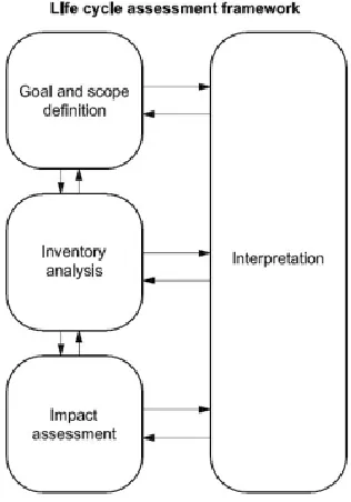
1. The Goal and Scope Definition phase-
This section includes the selection of system boundaries, functional unit definition to be used, allocation procedures, assumptions and limitations, impact categories to be analyzed and
interpretation methods. It is an iterative process since various aspects of the scope may change to meet the original scope of the study.
2. The Inventory Analysis phase-
This is an inventory of the input/output flows of the system under study. Collection,
[image:11.612.231.389.306.532.2]quantification and allocation of data are of key importance for this phase. This process is also iterative since the more the product is analyzed, the more is learned.
Figure 1: Phases of Life Cycle Assessment (ISO. 2006)
3. The Impact Assessment phase-
3
4. The Interpretation phase-
The final phase of a LCA study summarizes and discusses the findings, obtaining conclusions and making further recommendations for the system.
The direct applications of LCA as mentioned in ISO 14040 include product development, strategic planning, public policy making and marketing.
Following are some of the strengths of LCA mentioned by Marry Ann Curran (Walter Klöpffer 2014) -
1. Comprehensive assessment- Life cycle assessment is a ‘cradle to grave’ approach that helps in evaluation of environmental impacts associated with all of the Life cycle stages of the product. 2. Highlighting environmental tradeoffs- LCA assists in the identification of tradeoffs that occur due to
changes made to the system.
3. Structure for investigation- The ISO standards developed (ISO 14040) provide a general framework to conduct an investigation in four phases.
4. Ability to challenge conventional wisdom- LCA provides the data and information with which what is considered environmentally friendly can be questioned
5. Fosters communication and discourse- the LCA methodology has evolved as a basis to communicate the overall performance of products and services.
On the other hand a two part study pointed out 15 different issues and limitation that related to all of the phases in LCA (Reap et al. 2008). After assessing the severity of the problems and the solutions available the authors rated these problems and identified five critical areas which in their opinion require attention. These areas provide an overview for researchers to direct their efforts.
1. Functional Unit Definition – affects goal and scope
4
defining functional unit and defining reference flows resulting in an inaccurate representation of product system.
2. System Boundary Selection – affects goal and scope
Activities and processes to be included in the LCA study are determined by system boundary selection. “Boundary selection is influenced by product system’s unit processes, included life cycle stages, impacted
geographic area and relevant time horizon”(Reap et al. 2008). Appropriate selection of these boundaries requires large amount of data, time and costs with very little or no value added. Currently there are no clear practical guidelines and tools to support boundary selection.
3. Allocation – affects the inventory phase
Allocation refers to the assignment of environmental burdens of multifunctional process amongst its products or processes. There are various proposed solutions to tackle this issue but unfortunately there is no single method that provides a general solution.
4. Spatial Variation – affects the impacts assessment phase
Unlike global impacts the regional or local impacts require spatial information for accurately associating the sources of impacts. Even though various methods have been developed to address this issue most assessments ignore spatial considerations.
5. Data availability and quality – affects all four phases
Poorly measured data, data gaps and proxy data are the main sources of uncertainty in LCA results. Also, the data for life cycle inventories is not widely available. Data collection costs can be very large. In many cases the data may be outdated as it is compiled at different time periods. Data may also be
unrepresentative as it is taken from a similar but not identical process.
1.2 LCA in Product Development
5
The process of conducting a LCA is very time consuming.
LCA requires a lot of information which is usually not available during the design stages. The complex modelling approach used in LCA is not consistent with design models. Conducting LCA and analyzing its results requires special training.
LCA results are always subjected to a certain level of uncertainty.
Practitioners have developed Streamline Life cycle assessment (SLCA) methods to address some of the limitations presented above (Todd et al. 1999). These methods are simple, quick and less expensive to execute. As covering all of the process is a complex task, practitioners decide what to include in the LCA study based on their judgement and needs. It is proposed that if one stage of life cycle is dominant then the other stages may be streamlined considering their relative importance. Two of the popular SLCA methods are The Pollution-Prevention (P2) Factors methodology and AT&T abridged life-cycle
assessment. SLCA is not a very robust approach to apply during the design phase because it is very qualitative and subjective (Todd et al. 1999). These methods are less precise when compared to a complete LCA. Also, streamlining adds varying amounts of uncertainty to the results. Nevertheless, this approach may provide some initial guidance to the designers for choosing their focus areas.
(Yousnadj et al. 2014) argued that inherently LCA is not design oriented. It is designed to analyze the completely defined components and structures, but it cannot be used while deciding the product architecture or selecting certain set of components to satisfy the required functions. Also, the lack of correlation between the design parameters and environmental impacts makes it difficult for the
designers to interpret results.
With the limitations of the current methodology, LCA cannot be used by designers as a decision support system. LCA should help the designers to systematically generate and compare different
6
defined during this phase (Bohm et al. 2010). Hence environmentally conscious product development is a key issue that needs to be implemented in early design phases.
As was identified above all of the important decisions that guide the process of conducting an LCA are made during the goal and scope definition phase. Lack of proper tools and guidelines for defining appropriate functional unit and establishing system boundaries during this phase is a crucial issue that needs to be addressed. It is also necessary to develop a LCA model that can act as a decision support system for designers by efficiently modeling and evaluating changes. For developing such a model, the issues of time and data requirement and complex modeling approach need to be dealt with.
In the remainder of this thesis, Chapter 2 will discuss the literature review which will focus on the following three areas: CAD-PLM-LCA integrated tools, Functional Analysis in LCA and Object
orientation / Modularity in LCA. Chapter 3 will clearly define the problem statement. In Chapter 4 the methodology used to address the problem will be described with the help of a simple example. Chapter 5 will be dedicated to the details of a case study implementation. Chapter 6 will discuss the results and conclusions derived from the work. Chapter 7 will provide a discussion around the opportunities for the future work.
2.0 Literature Review
7
2.1 CAD-PLM-LCA Integration Efforts
Introduction of Computer-aided design (CAD) and Product Lifecycle Management (PLM) systems have revolutionized the design process (Morbidoni et al. 2012). The efforts to integrate the CAD-PLM and LCA systems to help designers develop eco-friendly products are reviewed in this section.
Jean-pierre Theret et al. (2011) explore the possibility to connect the design tools like CAD and PLM with environmental assessment tools such as LCA, so as to deliver products with lower
8
Part
Part lifecycle
Macro process 1
Sub process process 1.1
Sub process process 1.2
Machine
Raw material
Tool
Product Process Resource
Figure 2: PPR model - adapted from JP Theret, Evrard, and Mathieux (2011)
The EDW acts as a hub for collecting the data from CAD, CAE and PLM systems. It then validates the data and publishes the results with the help of environmental analysis applications like openLCA. The research work provides a tool that can assist in evaluating impacts of products defined in CAD-PLM systems, but it fails to demonstrate how the different solutions generated will be compared. It does not mention the way in which knowledge in the system will be reused to evaluate new designs. Only those designs that are completely defined in the CAD-PLM system can be assessed. An important
limitation of the EDW as mentioned in (Yousnadj et al. 2014) is the decontextualized environmental data link between the environmental results and the design parameters is lost.
9
study is that it did not explore how the environmental performance of design alternatives can be assessed to assist designers in making decisions. The usefulness of the tool is questionable when applied during the conceptual design phase where different options are evaluated by designers.
As mentioned above, in order to perform quick and easy analysis in the design phase simplified life cycle approaches have been developed. Morbidoni et al. (2012) attempt to connect SLCA tools with CAD tools to produce reliable environmental assessment results that can be visualized at an early design phase. The proposed framework consists of three modules, namely LCA software, CAD software and the user interface. The product structure and geometric information is extracted from the CAD models. The user interface allows the user to select the manufacturing processes, materials, the processes involved in the use phase and the end of life phase from an LCA database. An important feature is that the
manufacturing processes are connected to the machine database of the company. This ensures that real process data is computed.
In order to facilitate comparison, results are displayed in form of graphs and data in the user interface. A case study was implemented on a washing machine and the results were obtained based on different life cycle phases. The results demonstrated that a ‘cradle to grave’ evaluation of product is possible by integrating SLCA and CAD systems. One of the major weaknesses of the tool is that it requires a lot of human intervention and increases the designer’s efforts. The framework only supports the detailed design phase.
Germani et al. (2013) proposed a new methodology for the designers with no specific knowledge of eco-design processes to develop sustainable products. A new software platform G.EN.ESI supports this methodology. In this methodology, some new steps are added to the traditional design process to address environmental constraints. The reengineered method consisting of six steps-
1. Functional Analysis
10
3. Determination of the environmental strategy and deployment in indicators (targets) 4. Guidance- Rules and guidelines
5. Sustainability check – LCA, LCC, specific modules and reports 6. Impact of the company decisions to the long-term company objective
In order to support the method, the software tools required are identified and integrated into a
platform. The G.EN.ESI platform consists of the following modules- CAD-PLM module, lifecycle design module, supplier web portal, guidance module and report module. A case-based reasoning module (CBR) helps the designers to use existing knowledge and guidelines to improve products. The research does a good job in identifying and integrating different tools. It also does highlight that functional analysis is an important step in the design phase that helps to group components in modules and to define a functional unit, but the software platform developed does not support functional analysis. In addition, there is no guidance to connect the functionality, reference flows, and design parameters with the impact indicators.
In order to allow designers to consider environmental issues during early design phases Yousnadj et al. (2014) attempt to connect SLCA and PLM. A four-step methodology is proposed and a system architecture is developed by this research.
1. Planning- Establishes the objective and scope of the study. It also applies LCA to some completely defined products that will serve as a reference to identify relevant Life cycle stages.
2. Definition of Required elements- Specifies the level of information required for conducting the LCA. It limits the data required and helps to structure results and indicators. It is proposed that results be stored in PLM.
3. System specification and development- Defines functional and technical specifications for the PLM.
11
This methodology has been implemented by using Teamcenter PLM system of Simens and SLCA. The researchers claim that one of the prominent aspects of this methodology is that it keeps the links between the environmental impacts and its sources in the product characteristics. But this platform is still under development and it has not been validated. Also, no attempt has been made to remove the uncertainties inherit in the LCA process that hinder its application in design.
Ostad-Ahmad-Ghorabi et al. (2009) present the efforts to develop a tool that links CAD-LCA for environmental assessment in the early design phase. Extraction of information from previous models for performing assessment of new products is an important aspect of the approach. The concept of Life cycle families is introduced, so that a full scale LCA of new products is not needed. Life cycle families contain parametric models of products which share common behavior. A reference value for comparison is set which is the best in class scenario. The new concept is compared to this reference value to asses if the product is performing better or worse. The following three steps summarize their approach: (1) Perform LCAs of existing products and store the results in the CAD system (2) Develop the LCA family database in form of parametric descriptions (3) Comparative evaluation of a new concept.
A case study was implemented with a crane manufacturing company to test the approach. The project was successful in terms of demonstrating a way to reuse previous knowledge in the CAD system for quick evaluation of new concepts, however the static nature of the LCA family database is a major shortcoming of the implementation. The LCA family is dynamic and growing and depends on the product under investigation. Also, the accuracy of defining the LCA family and its parameters will directly affect the accuracy of the LCA results. The establishment of product families is based on the Fuon theory (Collado-Ruiz and Ostad-Ahmad-Ghorabi 2010) that itself has various limitations that will be discussed below.
12
between the PLM system components and LCA software to facilitate quick and efficient data retrieval. The bidirectional link between PLM-CALCI helps to extract the product structure i.e. processes
associated with components and allocation parameters. A user interface is used to relate the data from the LCA and PLM software platforms. A prototype is implemented in the form of a test bed, only the
Mechanical Computer Aided Design (MCAD) module of PLM system is used (solid edge) and it is interfaced with the openLCA package. Different design solutions of a telescopic desk lamp were chosen for evaluation and the results were presented in graphical form. The tool helped to identify components with higher environmental impacts. The main advantages of the tool developed are speed of compilation, association of product design parameters with LCI parameters and immediate evaluation of design changes. The omission of usage, transportation and end of life phases form the product evaluation is a major drawback of the tool.
One of the major shortcomings of all of the CAD-PLM integrated tools discussed above is the lack of support for the conceptual design phase. This phase of design is dominated by techniques like functional analysis. In any product development stage, functional analysis plays a key part in the selection of technologies/solutions, finalizing product architecture and building of new design concepts.
2.2 Functional Analysis in LCA
“Functional analysis is a technique that helps to describe the functionality of the system in an
abstract manner without relying on the physical structure. This kind of representation allows for more degree of openness when generating solutions” (Otto and Wood 1998). Developing product architectures and function structure generation are important applications of functional design. In this section, the efforts made to highlight the importance of functional analysis in the conceptual design environment for developing products with least environmental consequences will be discussed.
13
information on artifact function, failure, physical parameters, performance models, sensory information and media for over 130 electro-mechanical products. In this methodology, functional modelling is used to describe the product in the form of flows of material, energy and information. This functionally
decomposed model is supplied to the automatic concept generator that creates different concepts based on each function. A ‘cradle to gate’ impact evaluation of these concepts is performed by comparing them
with similar functionality models stored in the design repository. The results are then presented to the designers for selection and analysis.
While the method successfully presents the use of design repositories and concept generator for designing environmentally sound products, the method does not address a possible way to include use, transportation and end of life scenarios for evaluation. Also, the issue of the difficulty of comparing LCA results, particularly due to the lack of a standardized functional unit definition is not addressed.
Devanathan, et al. (2009) develop a novel semi quantitative tool, specifically for early design stages. An attempt is made to connect the functional data to the environmental impacts through the product structure. A new tool Function Impact Matrix (FIM) is introduced to achieve this. The FIM uses the information from the function-to-component mapping matrix to distribute the impacts across
functions. This approach helps the designers to identify which functions are important form an
environmental perspective. LCA results of the benchmarked products are integrated into the WKM so that they can be compared with new products. Along with the traditional function-to-component matrix the FIM is used to generate new concepts. In order to find the extent to which each component satisfies a particular function, percentage contributions need to be assigned. However, there is no specific method or guidance given on doing this. The impact values generated are specific to the function- structure
combination under analysis and cannot be extended to other combinations.
14
in engineering design to address this need. The authors present a concept they call a ‘Fuon’ that connects the functional behavior to the functional unit to allow scaling of results within the LCA. Parameters are used to define the Fuons that represent main function and enable scaling. These Fuons can be used to compare different products and also compare product concepts with the existing ones. The researchers demonstrate the idea by developing two Fuons, namely “Physical Container” and “Logistics-intensive Element”. The physical Container Fuon is shown in Figure 3. Their work establishes a link between
design theory and LCA and as such it may help the implementation of LCA in early design phase. However, the research does not clarify the implementation strategy of the method for complex products and full scale LCA. An attempt to improve this work is presented below.
Name – Physical Container
Description- Element that encloses partly or totally other physical elements, protecting them or isolating them from external environment
Flow diagramMM StoreStore MM
Parameters-
1] Physical parameters- Volume contained, weight supported, Number of storages
2] Constraint parameters- Thermal max temp, Mechanical constraints, dimensional constraints
Name – Physical Container
Description- Element that encloses partly or totally other physical elements, protecting them or isolating them from external environment
Flow diagramM Store M
Parameters-
1] Physical parameters- Volume contained, weight supported, Number of storages
2] Constraint parameters- Thermal max temp, Mechanical constraints, dimensional constraints
Figure 3: Physical Container Fuon (Adapted from Collado-Ruiz & Ostad-Ahmad-Ghorabi, 2010)
15
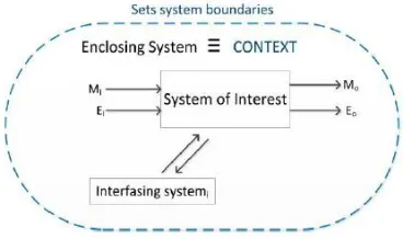
[image:24.612.228.412.145.254.2]generation and comparison of multiple use scenarios based of consumer behavior. The proposed framework is shown in Figure 4.
Figure 4: Generic LCA system framework (Esterman et al. 2012b), used with permission
A very exciting opportunity mentioned in this paper for the future work is the application of the same framework to the functionally decomposed system. “The application of the method to the sub functions
will help in developing building block elements for LCA studies that can be integrated. This observation is important because it implies that the Object Oriented Paradigm can be applied to LCA” (Esterman et al.
2012a).
2.3 Modularity / Object Orientation and LCA
Modular products are defined as “machines, assemblies, or components that accomplish an overall function through a combination of distinct building blocks or modules”(Otto and Wood 1998).
Two of the main advantages of modularity are standardization and re- configurability. In this section the importance of modularity when applied to LCA will be discussed.
Buxmann, Kistler, and Rebitzer (2009) propose a different approach for Life cycle assessment they term as ‘Modular LCA’. The approach starts with the concept of an Independent Information Module (IIM). Information modules are set up for each unit process or a combination of processes. At the core of the IIM are the ‘foreground processes’ which are the main processes under consideration for which data
16
connected to a background data from generic processes like disposal and recycling. Thus, the extension of unit process with the input and output data based on reference flow forms a module. The work was focused on manufacturing processes and not products, hence the unit of analysis is a process. In this modular LCA approach all of the classification, characterization and assessment is done at the process level as opposed to conventional LCA where these steps are performed on the systems level after aggregation of all the data. One of the important advantages of this approach is the creation of reusable elements that can be integrated. In conventional LCA a later distinction between the data is not possible, this is not the case with Modular LCA.
The research explains this process considering only the manufacturing phase. The application of this approach to Product Development should be explored. A designer is interested in the technical design parameters which can be varied. If an LCA expert setting up the system identifies these parameters and defines the modules accordingly, then it will provide a direct decision support model. As the model is specifically targeted for designers it will reduce the dependency on LCA experts for making all of the decisions. The role of the LCA expert will be limited to defining new modules, the addition of parameters and for making major changes to the model.
In the eco-design area the focus of academia and industry is shifting from product improvement and product redesign to Alternate Function Fulfilment (AFF ) and systems innovation. Recchioni et al. (2007) introduce the concept of modularity in product development to facilitate implementation of LCA in the early design phase. The researchers argue that in order to apply LCA to a modular system two characteristics will be of great importance namely ‘Attribute Independence’ and ‘Process Independence’.
17
way a certain module satisfies its functions, these do not influence other modules and hence the Life cycle can be analyzed individually. This reduces the time and the data required for an LCA study and supports its application in early design stage.
The research does a good job in demonstrating the importance of modularity to aid in the application of LCA in the conceptual design stage. But the research does not provide a methodology to compare different modules that perform the same function. The work also neglects the use phase while comparing the modules, and it fails to present how the use parameters will affect the comparison. Also, the concept will hold true only if the connections between the modules are systematically established. It is important to find out how the life cycles of these modules integrate with the help of interfaces to form a complete product system.
Recently design synthesis tools have been developed to automate the process of developing complex products. These design synthesis tools generate a solution space that contains various alternative solutions to solve a given problem. Helms and Shea (2010) introduce an object-oriented principle to design synthesis tools to make them more flexible, intelligent and efficient. First, the research draws parallel between object orientation and design synthesis. Then it explains how graph grammar techniques can be used to implement the approach. The graph grammar captures design knowledge from various sources, for example a design catalogue, and then uses this knowledge to generate solutions. The authors explain that this process has various levels of abstraction/modularity and involves the reuse of knowledge, hence a class level structuring scheme is essential.
18
along with the design parameters form the meta model. The actual execution is based on the rules and logic in the meta model. The execution operates with actual data objects.
The separation of the definition and execution phases enhances reusability of the meta-model for multiple applications and improves flexibility. It is important to note that different meta-models are comparable only if the naming conventions are followed i.e. a standardized approach is used for functional modeling. The concepts of this research provide a good guidance for developing an object- oriented LCA software.
3.0 Problem statement definition
After reviewing the different integration efforts to connect the CAD and PLM systems with LCA it can be concluded that these tools are helpful in the detailed design phase when the bill of material and the product structure is known, but they provide less assistance when it comes to supporting the
conceptual design phase which is when the technologies are selected and the product architecture is developed. None of these tools effectively integrate the use of functional analysis during the design phase so as to aid in the generation and selection of solutions taking into consideration their environmental impacts. Also, many of the tools reviewed did not effectively address the lack of standardized processes to perform LCAs. Relative to the efforts to use functional analysis concept in LCA, the work of
Esterman, et al. (2012a) is important because it gives a standardized methodology to integrate functional analysis with the LCA. Lastly, the literature was clear on the benefits of integrating modularity and object orientation into LCA, particularly to help in its integration into the early design environment.
The application of the framework presented in Esterman, et al. (2012a) to a functionally
19
methodology and it will then be applied to a more complex electro-mechanical system. The
implementation platform for the methodology will be SimaPro, which is a leading LCA software. While executing the methodology in a software environment, implementation issues will be identified and resolved. After the approach, has been implemented on the electro-mechanical product, the outcomes will be analyzed to understand the advantages and shortcomings of the approach. Finally, suggestions for improvements will be made and some guidance for the future work considering limitations of the current implementation will be provided.
4.0 Methodology
4.1 Methodology STEP 1: Functional decomposition and identification of
reference flows
“Functional analysis is a technique that helps to describe the functionality of the system in an abstract
manner without relying on the physical structure. This kind of representation allows for more degree of openness when generating solutions” (Otto and Wood 1998). The function of the product describes what
the product is supposed to do, the function can be thought of as the reason for existence of product. Otto and Wood (1998) define a function as “A statement of clear, reproducible relationship between the available input and desired output of the product, independent of any particular form”. Usually the function is described by a ‘verb-noun’ pair. For example, the function of a hand dryer can be expressed as ‘Dry Hands’, similarly the function of printer can be expressed as ‘Print Documents’.
The main idea is abstraction i.e. ignoring the particular solutions and concentrating on
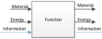
generalization. Emphasize needs to be on ‘what’ is to be done rather than ‘how’ it is done. The black box
20 Function Material Energy Material Energy Information Information
Figure 5: Black Box model, adapted from (Otto & Wood, 1998)
The overall function of the product can be dived into various sub functions. This is done by asking the question ‘how is the main function achieved’. The sub functions are the components or tasks
that are necessary to satisfy the main function. The sub functions are also represented in the form of black box model i.e. the abstraction is still maintained. The sub functions can be decomposed further, by asking the same question ‘How is the sub function achieved’. For verification, it is important to ask the question ‘Why is the sub function performed’. The answer to why should be a higher order sub function. The ‘How-Why’ logic will lead to a structure of all the black boxes at different levels connected to each other
known as a hierarchical function structure. This structure provides clear boundaries and at levels of similar abstraction and hence it is a very important tool for implementing object-orientation. This approach is known as hierarchical functional decomposition and is represented in the Figure 6.
Main Function Material Energy Material Energy Information Information
Sub function Sub function
Sub function
Sub function Sub function Sub function Sub function
Level 1: Main function
Level 2: subfunction
Level 3: subfunction
[image:29.612.235.408.71.138.2]Material Energy Information Material Energy Information Material Energy Information Material Energy Information Material Energy Information Material Energy Information
21
The ‘verb-noun’ representation of a function does describe the purpose of existence of the product, but it was discovered through our experience that to support an object-oriented LCA approach it is helpful to represent the function in the form of the transformation of material, energy and information inputs into material, energy and information outputs. In practice, the predominate flows that are
transferred are material followed by information. Since energy flows tend to be solution specific, they only tend to be a flow common to all systems if the purpose of the system is energy conversion.
Thus, the more comprehensive function descriptor that we adopt in this work is of the form ‘verb-noun pair-inputs’ to ‘verb ‘verb-noun pair-outputs’. For example, the function of the printer that was earlier expressed as ‘print documents’ can be expressed as ‘Mark Media to Print Documents’. While clearly
there are energy inputs into this system, they are not shown in Figure 7 because they are specific to the technological solution and hence not considered to be a flow common to all systems of this class.
Mark Media to Print Documents Media
Marking material
Content
Document
Figure 7: Black box model of a Printer
22
functions. Functional decomposition is an iterative process; assumptions are made from one level to the next.
The process discussed above is explained with the help of functional decomposition of a can opener. The can opener as the name suggests is used to open the can so that user can access contents inside the can. The main function in the black box form is shown in Figure 8.
Can
Lid
Separate Lid to Access Contents
Can + Contents + Lid
Can -Sealed
Can -Unsealed Contents
Figure 8: Black box model of Can Opener
The material input into the black box is the can along with its contents and the lid. The
information flow is the sealed state of the can. The material transformation leads to the separation of the lid from the can thus changing the state of the can form sealed to unsealed and allowing access to the contents. This main function along with the flows establishes a class of systems that can be used to make this transformation. Different types of can openers like the lever type, the rotating wheel type and even the electric can openers satisfy the same function mentioned above and lead to the same material and information transformations.
The question is the asked, “how is the main function, separate lid to access contents, achieved”?
The answer to this questions allows for the continued decomposition of the function structure into three sub-functions: access can, puncture can and rotate can. Note that even these second level functions are very generalized i.e. they are independent of any particular technology used to enable these
23
Puncture Can Can & Contents
+ Lid
Can & Contents + Lid
Can -Unpunctured Can -Punctured Rotate Can Can + Contents
+ Lid
Can -Sealed
Can + Contents
Lid Can -Unsealed Can
Lid Separate Lid to Access Contents Can + Contents + Lid
Can -Sealed
Can -Unsealed Contents
Access Can
Can + Contents + Lid Can & Contents + Lid
Can -Position
Level 1 -Main function
Level 2 -Sub function
Figure 9:Level 2 sub functions of Can Opener
This same logic is applied to further decompose the second level functions into third level sub-functions.
A] Access Can - In order to access the can, it first needs to be located so it can then be secured.
Level 2 -Sub function
Level 3 -Sub function
Locate Can Can -Position
Secure Can
Can & Contents + Lid Can & Contents + Lid Can -Unsecured Can -secured
Access Can
Can + Contents + Lid Can & Contents + Lid Can -Position
Figure 10: Access can decomposition
B] Puncture Can- The can is punctured by gripping the edge of the can and penetrating the lid.
Level 2 -Sub function Level 3 -Sub function
Puncture Can Can & Contents
+ Lid
Can & Contents + Lid
Can -Unpunctured Can -Punctured
Penetrate Lid Can
-Unpunctured Can -Punctured Can + Contents + Lid Can + Contents
+ Lid Grip can edge
Can edge- Ungripped
Can edge- Gripped
24
C] Rotate Can- Similarly, for rotating the can a torque must be applied and transmitted as well as restricting the linear motion of the can. When the can is rotated completely the lid is separated from the can thus changing the state of can to unsealed. Hence now the contents inside the can now be accessed.
Apply torque Transmit torque Restrict Linear motion
Level 2 -Sub function
Level 3 -Sub function
Rotate Can Can + Contents
+ Lid
Can -Sealed
Can + Contents
Lid Can -Unsealed
Figure 12: Rotate Can decomposition
The above structure generated can be verified by asking, “why is the function needed?” for each of the third level sub-functions and subsequently the second level sub-functions. This is an important step to ensure that the decomposition makes logical sense. Note that even though the third level of
decomposition is still fairly general, decisions have been made about the solution, namely that it will be done through mechanically puncturing the can and then rotating the can itself. This is unavoidable and they key is to make these decisions in a controlled manner.
If taken to its logical conclusion, this How-Why logic will ultimately lead to the definition of components that fulfill very low level functions. Given the relative simplicity of the open can function, after the 3rd level a particular technological solution is, for all intents, defined. When that happens, a
25
The ‘bottoms-up’ reverse engineering approach that is implemented is called the ‘Subtract and Operate’ procedure (Otto and Wood 1998). The process is started by considering the most basic functions
of components and features. The removal of each of these components and features is mentally simulated and thus the effects of operating the system without them can be deduced. From this, the functions of the components and the features can be established. These low-level functions can then be integrated into the top-down structure that was generated previously through the use of the how-why logic that was
described above. There should be a reason for all of the components to be there and thus all of the solution specific sub-functions identified using this approach should roll up and map into the structure generated using the ‘top-down’ approach. Any components, features and lower level sub functions that cannot be mapped expose the gaps in the function structure. To close these gaps either new higher level functions need to be identified or the existing functions need to be rearranged.
For illustration purposes, a simple butterfly can opener, which is shown in Figure 13, was used. First the user locates and grips the can manually. A small notch is made initially into the lid by
applying the force to the main arm, which gets transmitted to the cutting blade. As the user turns the
handle the can is rotated so that the blade continues cutting along the circumference of the lid until it
gets separated from the can.
26
The next step is to develop a Bill of Materials as shown in Figure 14. Note that as this is a simple device no subassemblies were present. Appropriate engineering assumptions have been made with respect to material and manufacturing processes for parts.
Figure 14: BOM-Can opener
In order to understand the basic functions of these parts the operation of can opener with removal of these parts is mentally simulated. For example, if the main arm is removed then the force required to penetrate the lid of the can cannot be generated. Similarly, the blade is removed the lid would not be penetrated. Once these basic functions are understood the question of which higher level functions are supported by these basic functions is addressed. For example, ‘creating a notch’ and ‘applying cutting force’ are essential to perform the higher-level function ‘Penetrate Lid’ which identified earlier in the
27
Penetrate Lid
Apply cutting force Create Notch Can -Sealed Can -Punctured Can & Contents
+ Lid
Can & Contents + Lid
[image:36.612.88.538.287.535.2]Main Arm Blade
Figure 15: Structure mapping -penetrate lid
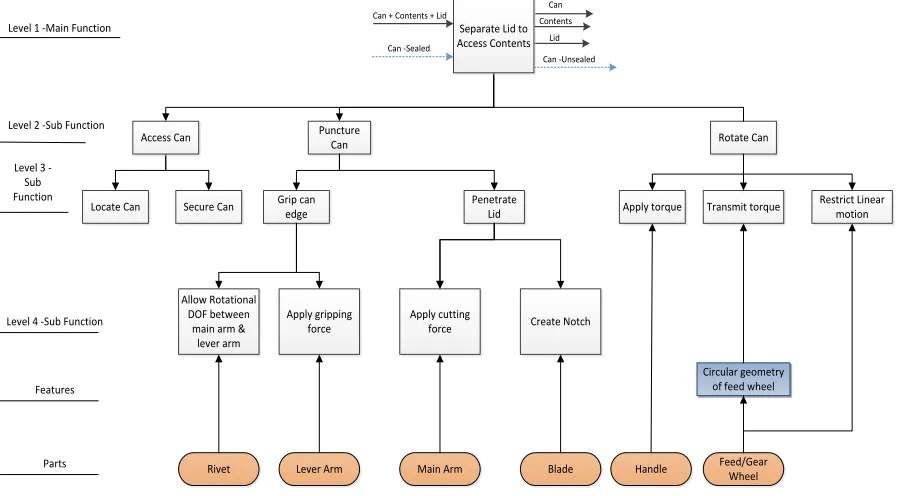
Locate Can Access Can Grip can edge Allow Rotational DOF between
main arm & lever arm Apply gripping force Penetrate Lid Apply cutting
force Create Notch Puncture
Can
Apply torque Transmit torque
Rivet Lever Arm Main Arm Blade
Restrict Linear motion
Handle Feed/Gear Wheel Circular geometry
of feed wheel Rotate Can
Secure Can Level 1 -Main Function
Level 2 -Sub Function Level 3
-Sub Function
Level 4 -Sub Function
Parts Features
Can
Lid
Separate Lid to Access Contents
Can + Contents + Lid
Can -Sealed
Can -Unsealed Contents
Figure 16: Function- Structure diagram of Can opener
4.2 Methodology STEP 2: Establish Use parameters, System parameters and Cumulative
Damage Function (CDF)
28
the system that implements this function and system parameters for the subsequent implementation of the sub-functions that support the main function. The use parameters are used to model the user behavior. The use parameters identified are not specific to any particular technology as they are derived from the reference flows. Changes in the consumer pattern can be modeled by changing the values and
combinations of the use parameters.
For the can opener the main input flow of material is the can itself along with the contents and lid. The user selects the type of can that needs to open, hence type of can is an important use parameter. Associated with the type of a can is information like the can diameter, lid thickness and material properties of the can. Another important part of the user behavior is the frequency of use of the can opener. Some users may use the can opener very frequently while the other may not. To model this another parameter, number of cans, is defined. Thus, two use parameters for the main function pierce can to separate lid are- 1] Number of cans 2] Type of can (Diameter, Lid thickness, Material).
These use parameters further act as an input to determine the system parameters for the sub-functions. Each sub-function is considered as an independent system, hence the parameters that are used to define the behavior of the sub-functions are called as system parameters. It is important to establish the relationship between the use parameters and the system parameters. Once relationships are in place the changes to the use patterns will be automatically translated into the changes in system parameters at the lower levels. This will help to guide the selection of technological solutions based on user behavior. Note that if the sub-functions were stand-alone subsystems, what are referred to a system parameters become use parameters.
29
sub-function is considered outside of the boundaries of our current model, it is important still to have this sub-function in the decomposition because in it necessary to accomplish the main function and in the future, it may be decided to satisfy this function through a technological solution like an intelligent can opener. The system parameters for the other two sub-functions and their relation with the use parameters are established as shown in the Table 1.
Table 1: Use & System parameters of Can opener
Main Function Use Parameters – 1] Type of can (Diameter, Lid Thickness, Material) 2] Number of cans
Sub Function System Parameters
A] Puncture Can 1] Puncture Force = f (Lid Thickness, Material) 2] Puncture depth= f (Lid Thickness)
3] Puncture cycles =f (Number of cans) B] Rotate Can 1] Rotational force= f (Diameter, Material)
2] Rotation cycles = Number of cans
Consider the sub-function ‘Puncture Can’. The following three important decisions are to be
made at the sub-functional level of ‘Puncture Can’. 1] What force should be applied to puncture the lid given the thickness of the can lid used by the user and
the material properties of the can? The information required to determine this force can be obtained from the use parameter ‘Type of can’.
2] What should be the depth of the penetration? The depth of the penetration should be equal to the thickness of the lid and this information again can be obtained from use parameter ‘Type of can’.
30
Now consider a scenario where in the user operates the can opener to open 200,000 cans during its life time. Hence the use parameter ‘Number of can’ is set to 200,000. It is further assumed that the user intends to open the same type of can with a thickness of 1mm, diameter of 120mm and having material constant Z (shear strength) = 2 N/mm2. The information from this use scenario can be used directly to derive the three system parameters for ‘Puncture can’ using the following relationships. It was assumed
that there exists an empirical formula to calculate the Puncture force.
Puncture Force= 25 x Z x Lid Thickness= 25*2*1= 50N ( 1 )
Puncture Depth = Lid Thickness= 1mm ( 2 )
Puncture Cycles= Number of cans = 200000 ( 3 )
The system parameters for ‘Rotate Can’ sub function can be obtained similarly. ‘Puncture can’ and ‘Rotate can’ have been identified as two modules. The current research does not provide a method to
identify independent subsystems from the functional block diagram. Modules/building blocks have been identified based on the separation of flows and the knowledge about the structure of solution. But the future work section does mention some of the approaches that can be used to address this.
The consumption of the system out of the total life of the system is based on usage pattern. This fraction of life consumed is calculate with the help of Cumulative Damage Function (Fumagalli 2012). The following equation explains the CDF -
CDF = Consumed Life / Limit (Lf, Lobs, Lneed) ( 4 )
Consumed life- Represents use scenario under consideration
Lf = Limit due to failure
Lobs = Limit due to obsolescence
31
As a function of usage parameter, a certain life of the particular unit of interest will be consumed, this is main idea behind CDF. Thus, the CDF’s can be calculated for each of the building block identified. We have already defined the relationships between the use parameters and system parameters which will help in scaling of the CDF’s of individual building blocks based on usage. With change in user behavior the use parameters will change which will in turn drive changes to the system parameters which will further drive changes to the CDF values. Note- The details of the CDF determination methodology are presented in the work (Deo and Esterman 2016)..
Consider the can opener example, the ‘Puncture Can’ sub function is an individual building block. The following method is used to calculate the CDF of ‘Puncture Can’. First, the operational
stressors acting on the block is identified. Stressors are not defined that are specific to a particular technology, rather a class of stressors is developed, for example – Mechanical stressors, Electrical stressors etc. As a next step, a Failure mode effects and criticality analysis (FMECA) based on the
functional decomposition is developed. This FMECA will help to identify the probable failure mechanism for the most critical component of the building block. It is concluded the FMECA that the most critical component fails by wear which leads to failure of entire functional block. Hence the models that can be used to calculate wear are explored. The most common model for wear is Archard’s law which is given
by
V= K x Fn x S ( 5 )
V- volume of material removed per operation
K-material constant
Fn = normal force
32
Consider that Vcris the critical volume of material lost before the function fails and Ncr is the
critical number of operations for functional failure. Considering Archard’s law the following relation can
be established:
𝑁𝑐𝑟 =𝐾𝑥 𝐹𝑛 𝑥 𝑆
𝑉𝑐𝑟 ( 6 )
Out of the above parameters, the values of Fn and S can be derived based on the system
parameters for ‘Puncture can’. Fn is the normal force which is equal to the system parameter puncture
force (50N), similarly the value of S is equal to the system parameter puncture depth (1mm). The other two parameters Vcr and K are dependent on technological solution employed. Suppose the supplier of the sub assembly provides us with this information Vcr (assumed to be 0.001 mm3) and K (assumed to be 2 N/mm2) or the information is derived from previous design knowledge, CDF can be calculated.
𝑁𝑐𝑟 =2𝑥 50 𝑥 1
0.001 = 100000 𝑢𝑛𝑖𝑡𝑠 ( 7 )
𝐶𝐷𝐹 = 𝑇𝑜𝑡𝑎𝑙 𝑛𝑢𝑚𝑏𝑒𝑟 𝑜𝑓 𝑜𝑝𝑒𝑟𝑎𝑡𝑖𝑜𝑛𝑠
Number of crtitcal operations =
𝑁𝑢𝑚𝑏𝑒𝑟 𝑜𝑓 𝑐𝑎𝑛𝑠
𝑁𝑐𝑟 =
200000
100000= 2 ( 8 )
Thus, the details of the technological solution like its weight, geometry, bill of materials are not needed in order to compute the CDF. If the values of Vcr and K are available from standards or supplier data and the use parameters are known, then the calculations for CDF for ‘Puncture Can’ can be made.
Thus, for any block once the use parameters and the critical solution dependent parameters are known the consumed life can be calculated. Once these relationships are established any changes can be modeled just by changes the values of the parameters.
The same approach to calculate the CDF of ‘Rotate Can’ was described above was used and its
CDF also has a value two. Given the defined use scenario the two (CDF-puncture can) units of ‘Puncture can’ and two (CDF- rotate can) units of ‘Rotate Can’ are allocated to the main function of Separate Lid to
33
Figure 17: CDF allocation for Can opener
4.3 Methodology STEP 3: Implementation using SimaPro
SimaPro has been the world’s leading LCA software package for 25 years. It is trusted by industry and academics in more than 80 countries. (About SimaPro, 2016).
34
[image:43.612.107.507.155.413.2]following the hierarchy of the functional decomposition developed earlier. An assembly named Function-Structure was created which consists of the functional decomposition of the can opener, refer to the Figure 18.
Figure 18: Can opener Function-Structure in SimaPro
Consider the first level of the decomposition where the main function is broken down into three sub functions.
Puncture Can Can & Contents
+ Lid
Can & Contents + Lid Can -Unpunctured Can -Punctured
Rotate Can Can + Contents
+ Lid Can -Sealed
Can + Contents
Lid Can -Unsealed Can
Lid
Separate Lid to Access Contents
Can + Contents + Lid
Can -Sealed
Can -Unsealed Contents
Access Can
Can + Contents + Lid Can & Contents + Lid Can -Position
Level 1 -Main function
Level 2 -Sub function
35
Figure 20: Building Blocks in SimaPro
In SimaPro the Materials/Assemblies section is used to define the subassemblies or the materials that constitute the part/main assembly. In our case, lower level functions are the building blocks for the upper level functions, hence they are added to the section Materials/Assemblies to form the higher-level functions. Thus Figure 20 implies that the ‘Separate Lid to Access Contents’ function is a combination of puncture can and rotate can (access can is outside system boundaries, hence not added). The amount of module allocated to the main function is dependent on the CDF of that module.
Consider the next level of decomposition in which the rotate can is further decomposed, which is represented in Figure 21 . One unit of apply torque, transmit torque and restrict linear motion is allocated to the rotate can function. Thus, the ratio of allocation is 1:1. But as seen earlier 2 units of rotate can module are allocated to the main function, hence when a function structure is formed two units of these three lower level functions will be allocated automatically.
Apply torque Transmit torque Restrict Linear motion
Rotate Can
Can & Contents + Lid
Can -Sealed
Can & Contents
Lid Can -Unsealed
Level 2 -Sub function Level 3 -Sub function
36
Next the structure or the actual component is mapped to the lower level function. For example, the apply torque function is satisfied by the main handle. The main handle is defined in terms of its material, weight and the manufacturing process used as shown in the figure below. One unit of this main handle is then allocated to the Apply torque function. Note that the actual allocation of component to the main function is dependent on the CDF value of the module in which it is present.
[image:45.612.124.501.359.664.2]
Finally, we arrive at the final function-structure diagram which is shown in Figure 22.
Figure 22:Can opener Function-Structure in SimaPro
Apply torque
37
In the following part use parameters, system parameters and the CDF calculations are set up. The use parameters which are derived from the reference flows of the main function act as the global
parameters. These are defined in the parameters section under the inventory. The values of the use parameters are entered based on the use scenario. By changing these values different use scenarios can be constructed easily. These use parameters are accessible to any part of the system.
Figure 23: Use parameters for can opener in SimaPro
The next step is to calculate the system parameters and the CDF for the building blocks of the system. Consider the example of ‘Puncture Can’ in the Figure 24. Inside the parameters section of the assembly ‘Puncture Can’ two calculations are made. The system parameters are calculated based on the
38
Figure 24: System parameters and CDF calculation for Puncture can
SimaPro does not allow for a formula/expression to be entered in the section ‘amount’ for
allocation purpose, refer to the Figure 25. Hence in the current implementation once the CDF values are calculated for each module, these values need to be entered manually in the section ‘amount’. The practitioner has to identify the level of abstraction at which the module is formed and mapped to a higher-level function, then allocate the amount based on the CDF value calculated. For example, based on the user parameters and the input parameters the CDF value for the ‘Puncture Can’ module was calculated by
SimaPro as two, refer Figure 24. Based on the functional decomposition it was then identified that the ‘Puncture Can’ module maps into the higher- level function ‘Separate Lid to Access Contents’. Then the
39
Figure 25: Entering CDF values for allocation
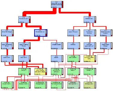
Finally, we can analyze the impacts of the can opener for a given use scenario using the end point impact assessment. The end point impact assessment calculates the impacts on human health, ecology and resources. The red bars indicate the environmental load generated by each block. The thickness of the red line and the red bars help to identify the environmental hotspots.
40
The drill down of the impacts throughout the hierarchy provides a structure for detailed
investigation. In the Figure 27 is it clear that the puncture can module has higher impacts. With the drill-down of the structure it is observed that, inside the puncture can module, penetrate lid function has higher impact values.
Figure 27: Environmental impacts of Puncture can & Rotate Can
[image:49.612.75.481.199.405.2]
41
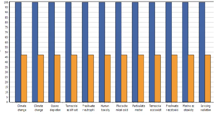
Apart from providing a hierarchical structure for investigation the parameters set earlier can be easily changed to evaluate different use scenarios. Different scenarios are constructed by simply changing the values of the use parameters. The system parameters and the CDF values are calculated as described earlier. Hence as the allocation is changed based on different user parameters, the impacts of new scenario can be compared to the old one. The new scenario is named S1. The new set of use parameter values is shown in Figure 29. Note that Parameters and the relationships are the same just the values have been changed to reflect changes in user behavior.
Figure 29: Use parameter for Scenario S1
Currently the changes in the use parameter values automatically change the values of system parameters as the relationships are already established. The CDF values can be calculated and the allocation of modules performed automatically, if the limitations of SimaPro are overcome in the future software platform. The Figure 30 shows the CDF values and system parameters of the puncture can module for the new usage scenario. The Figure 31shows the impact comparison of the original scenario and the new usage scenario.
42
Figure 31: Comparison of environmental impacts between two use scenarios
The methodology explained above is implemented on a complex electro mechanical system to understand the challenges and areas for improvement. Next section explains the case study
implementation on a Keurig 2.0 coffee machine.
5.0 Case Study Implementation
43
Table 2: Product selection criteria
Criteria Desired condition
Number of electromechanical parts present Higher number of electromechanical parts is desired as at will help to cover a broad range of functions they satisfy. Along with it time and resource constrains are to be taken in
consideration.
Presence of moving parts More number of moving parts are desired as it will help to cover a broad range of stress parameters degrading the system.
Presence of interactions System that actively interacts with human and requires human inputs is desired.
Generation of use cases Presence of higher use parameters is desired as it will help to generate and analyze multiple use scenarios.
Number of technologies covering the main function
Presence of multiple technologies covering the same functions is desired to illustrate
representation of a holistic system through functional decomposition.
Data availability Ability to generate the Bill of material
information through breakdown or other means is essential. Also, any possibilities for acquiring reliability data are to be considered.
5.1
The Keurig K 2.0 200 coffee brewing system-
Theory of operation
44
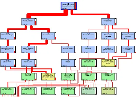
and allow the passage of pressurized hot water into the K cup for extraction. The solute of the hot water and coffee extracts exits the system through a dispenser. The user thus gets a freshly brewed coffee that can be collected into a cup or carafe. For overview of the Keurig system refer to the Figure 32 and for the schematic refer to the Figure 33.
Figure 32: Keurig system overview (Keurig use & care guide K2.0 series, 2015)
Water Reservoir
Water Heater
Extracti