HARDWARE/SOF TWARE SYSTEM DES IGN FOR A ROBOT ARM
by
Raymond Hang Yick Lam, B.E. (Hons.)
Submitted in fulfilment of the requirements for the degree of
Master of Engineering Science
UNIVERSITY OF TASMANIA HOBART
. 1987
I declare that this thesis does not contain anything that has been accepted for the award. of a degree or diploma in any other university, and also that, to the best of my knowledge and belief, the th�sis does not contain a copy or a paraphrase of material written and/or published by anyone else except where due reference to it is made in the text of the thesis.
CONTENTS
ABSTRACT v
ACKNOWLEDGEMENTS vii
CHAPTER 1. INTRODUCTION /
, 1.1 CONTRIBUTIONS / 1.2 THESIS OUTLINE /
1.3 DEFINITION OF ROBOTS 3 1.4 THE ROBOT SYSTEM 3
(a) Robot Manipulator (b) Robot Computer (c) Robot Power Source 1.5 TEACHING METHODS 10
(a) Off-line Programming (b) On-line Programming
(i) Individual-joint teaching (ii) Lead-through teaching
CHAPTER 2. THE TASROBOTO SYSTEM 14
2.1 THE MANIPULATOR 14 (a) The Arm
(b) The Wrist (c) The Gripper
2.2 THE ROBOT COMPUTER 19 (a) The Host Computer (b) The Controller Unit 2.3 POWER SOURCE 22
2.4 PROGRAMMING THE TASROBOTO MANIPULATOR 23
CHAPTER 3. HARDWARE DESIGN OF THE TASROBOTO CONTROLLER UNIT 25
3.1 THE ANALOG CONTROL BOARD 25
3.2 THE DIGITAL CONTROL BOARD 29 (a) The 12-bit Comparator
• (b) The 12-bit Up/Down Counter
(c) The Stepper Moter Driver • (d) The Controller Logic Unit
(i) The clock generator (ii) The pulse generator (iii) The direction signal
generator
3.3 THE INTERFACE CIRCUIT BOARD 42 (a) The Decoder And The Data
Register Circuit (b) The DAC Circuit
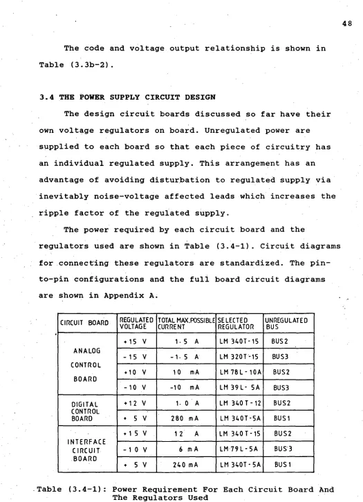
3.4 THE POWER SUPPLY CIRCUIT DESIGN. 48
•CHAPTER 4. IDENTIFICATION OF THE MANIPULATOR SYSTEM 5/
4.1 MODEL BUILDING 52
4.2 PARAMETERS TO BE IDENTIFIED 56 4.3 IDENTIFICATION TECHNIQUE 57 4.4 TEST INPUT 61
4.5 IMPLEMENTATION OF THE IDENTIFICATION PROCESS 64
4.6 CONVERSION FROM DISCRETE-TIME MODEL TO CONTINUOUS-TIME MODEL 66
4.7 RESULTS OF IDENTIFICATION ON THE THREE JOINT SYSTEMS 67
CHAPTER 5. MODEL ANALYSIS AND COMPENSATOR DESIGN 72
5.1 ANALYSIS OF IDENTIFIED MODELS 72 5.2 EFFECTS OF SATURATION NON-LINEARITY
ON STEP RESPONSE 73
5.3 EFFECTS OF DISTURBANCE TORQUE 80
5.4 EFFECTS OF DEAD-SPACE NON-LINEARITY 84
5.5 DESIGN OF CONTROLLERS 85
CHAPTER 6. TRAJECTORY PLANNING 95 6.1 PATH APPROXIMATION 97
6.2 SPLINE FUNCTION FOR EACH SEGMENT 99 (a) Cubic Splines For Intermediate
Segments
(b) Fourth-order Spline For The Beginning And End Segments
(c) Fifth-order Spline Function For A Two-point Section
6.3 TIME SCALE FACTOR 108
6.4 EVALUATION OF MAXIMUM VELOCITY AND
ACCELERATION FOR SPLINE SEGMENTS 112
6.5 METHODS OF IMPLEMENTATION 113
CHAPTER 7. SOFTWARE CONTROL OF THE TASROBOTO SYSTEM 118
7.1 SUBROUTINES 118
(a) The STPORT Subroutine (b) The DIGOUT Subroutine
(c) The POSITN, WRIST and ARMOUT Subroutines
(d) The BEEP Subroutine (e) The SELFADJ Subroutine 7.2 MAIN PROGRAMS 122
(a) The Initializing Stage (b) The Programming Stage (c) The Compiling Stage (d) The Executing Stage (e) The Intermediate Stage (f) The Idling Stage
7.3 THE SOFTWARE CONTROL BATCH FILE 139
CHAPTER 8. CONCLUSIONS AND FUTURE WORK 141
8.1 CONCLUSIONS 141 8.2 FUTURE WORK 142
REFERENCES 146
APPENDIX A. CIRCUIT DIAGRAMS OF THE CONTROLLER UNIT 149
iii
APPENDIX C. CONVERSION FROM DISCRETE-TIME TRANSFER FUNCTION TO CONTINUOUS-TIME FOR A
THIRD-ORDER SYSTEM 173
iv
ABSTRACT
This project is the design, implementation and
evalua-tion of a control system for a robot manipulator. It is initiated as a foundation research in robotics in the
Electrical Department, University of Tasmania. The TasrobotO is the first robot arm built in the Department. The design includes all the necessary electronic hardwares as well as softwares for the control of the manipulator.
A complete robot system is a multi-variable, interact-ing and non-linear system with time-varyinteract-ing parameters. As Hewit has pointed out: "no applicable corpus of control theory exists to deal with systems possessing such a
combination of problematic features", the design of suitable 'controllers is impossible without making assumptions to
simplify the system.
As it is still in the developing stage, the size and weight of the TasrobotO manipulator is far less than
• commonly encountered working robots. The interactions
between the manipulator links are small. The joint systems are thus assumed to be mutually independent systems, with time-varying parameters resulting from changes in the arm configuration. With a suitable controller, this time-varying effect was shown to be insignificant in the closed-loop
•dynamic response of each joint system. •
optimality in the sense that it defines the shortest curve passing through the specified points while at the same time satisfying the velocity and acceleration contraints. In the operation mode, command signals are generated in real time from segment functions derived for each joint to control its motion. This helps smoothen jerky motions and reduce the deviations of the executed path from the planned path.
The design and developed techniques have been tested and are in use today controlling TasrobotO.
ACKNOWLEDGEMENTS
I would like to express my thanks to the following people:
My supervisor Mr.Gregory The for his enthusiasm and constant assistance in my process throughout the thesis.
My parents, brothers and sisters, who have provided encouragement and support during my study overseas.
The workshop staff of the Electrical Engineering
Departments, especially Mr.Bob Barclay and Mr.John Grace, for the equipment they have made for me.
Finally,, my thanks to Ms.May Wong, my best friend, who helped prepare the drawings and edit the final draft of the thesis.
CHAPTER ONE
INTRODUCTION
1.1 CONTRIBUTIONS
The contributions of this thesis are:
+Development of a technique for modelling and control-ling small and light weight robot arms.
+Development of a trajectory planning technique which guarantees continuity in joint velocities and acceler- ations of a robot manipulator. The technique also
ensures the joint velocities and accelerations are within the mechanical limits of the manipulator. +Development of a system identification software
pack-age for identifying third order systems. The packpack-age is also applicable to higher order systems upon minor modifications.
•Development of a technique to convert transfer funct-ions from discrete-time model to continuous-time model with zero-order-hold data extrapolator.
•A paper[R 3 e] on the identification and control •system design of a robot manipulator was accepted by the IASTED for presentation at the 15th IASTED
International Conference on Applied Simulation and Modelling, held at Santa Barbara, California USA on May 26-29, 1987.
+Two papers, one on the identification and control of a robot manipulator, one on the technique of trajectory planning of a robot manipulator, were accepted for presentation as poster papers at the IREECON '87. Regretfully, these papers have to be withdrawn due to lack of Department travel funds.
1.2 THESIS OUTLINE
Chapter 1 starts with the contributions and thesis outline, continues with a brief description of a robot system and ends with a review of the programming methods commonly encountered in robot systems.
Chapter. 2 describes the mechanical structure and the control schemes of the TasrobotO manipulator.
Chapter 3 summarizes the hardware design implementing the control schemes discussed in chapter 2. Hardware inter-face to the IBM/PC microcomputer, the host computer of the TasrobotO system, is also included.
Chapter 4 describes the model building technique for
the joint systems. Also detailed are the theories, techniq-ues and results of the identification of the model
parameters.
Chapter 5 contains an analysis of the results in chapter 4. A complete model of each joint system is estab-lished to facilitate controller design. Non-linearities and time-varying parameters of the joint systems are also
addressed.
Chapter 6 describes techniques for trajectory planning
and path execution.
Chapter 7 reviews the software design of the control
system of TasrobotO. It contains detailed descriptions of developed softwares for robot programming, trajectory planning and path execution.
Chapter 8 summarizes the contributions and gives
possible extensions to the work as motivation for further work.
1.3 DEFINITION OF ROBOTS
In order to distinguish a robot from many
single-purpose machines, which have some features making them look like robots, a clear definition is important. The definition developed by the Robotics International Division of the
Society of Manufacturing Engineers (RI/SME) is as follows:- "A robot is a reprogrammable multifunctional manipulator designed to move materials, parts, tools, or specialized devices through variable programmed motions for the performance of a variety of tasks."
Reprogrammable in the definition means that the machine can be programmed repeatedly to perform a new or different task. The definition also emphasizes multifunctional which means that the machine must be able to perform many different functions, depending on the program and tooling used. By this definition, most single-purpose machines are not
classified as robots since they are usually not programmable and can only perform single function. Even though
tele-operators look like robots, they cannot be classified as robots according to the robot definition because they
require human operator to perform a task at a distance and are not programmable.
1.4 THE ROBOT SYSTEM
At present, industrial robots are actually mechanical handling devices that can be manipulated under computer
4
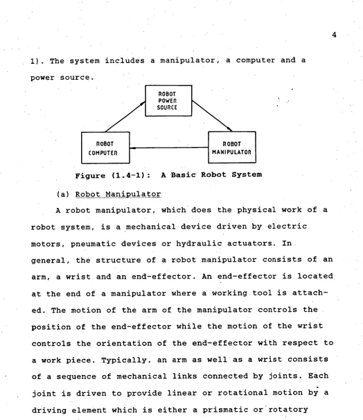
1). The system includes a manipulator, a computer and a power source.
ROBOT POWER SOURCE
ROBOT ROBOT
COMPUTER MANIPULATOR
Figure (1.4-1): A Basic Robot System
(a) Robot Manipulator
A robot manipulator, which does the physical work of a robot system, is a mechanical device driven by electric motors, pneumatic devices or hydraulic actuators. In
general, the structure of a robot manipulator consists of an arm, a wrist and an end-effector. An end-effector is located at the end of a manipulator where a working tool is attach-ed. The motion of the arm of the manipulator controls the position of the end-effector while the motion of the wrist controls the orientation of the end-effector with respect to a work piece. Typically, an arm as well as a wrist consists of a sequence of mechanical links connected by joints. Each joint is driven to provide linear or rotational motion by driving element which is either a prismatic or.rotatory
[image:12.559.26.550.19.625.2]BODY SWEEP SHOULDER
SWIVEL (
RECTANGULAR
SPHERICAL
ELBOW EXTENSION
The positioning of an end-effector in space requires motion of at least three
degree-of-freedom and is controlled by the motion of the manipulator arm. A typical structure of an arm consists Figure (1.4a-1): A Typical
Structure of An Arm of A
Manipulator of three links as shown in
Figure (1.4a-1).
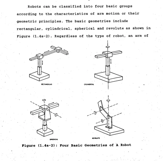
Robots can be classified into four basic groups according to the characteristics of arm motion or their geometric principles. The basic geometries include
rectangular, cylindrical, spherical and revolute as shown in Figure (1.4a-2). Regardless of the type of robot, an arm of
REVOLUTE
[image:13.559.15.546.19.727.2] [image:13.559.19.546.302.825.2](a) ROLL- PITCH -YAW ANGLES
./
(b) EULER ANGLES
6
a robot typically consists of three movable joints. The combined motion of these three joints enables the
manipulator to move to required position within its work space.
The orientation of the end-effector is controlled by the motion of the manipulator wrist. The wrist motion is often a sequence of axial rotations which provide three-degree-freedom motion for orientation of the end-effector. The two types of angles most frequently used to describe orientation of the wrist motions are the Euler angles and the Roll-Pitch-Yaw angles as shown in Figure (1.4a-3). A combination of these axial rotations enables the end-effector to take any arbitrary orientation in space.
Nevertheless, there are robots whose wrists are capable of only two or even one degree-of-freedom motion. These types of robots, however, have limitations in their applications.
Figure (1.4a-3): Two Typical Types of Angles describing Wrist Motions
(b) Robot Computer
7
the motion of a manipulator. It senses signals from sensors on the manipulator and generates appropriate command signals to drive the manipulator.
• A robot computer block can be divided into tiqo units,
the intelligent unit and the controller unit. The
intelligent unit is often called the host computer, whose functions are to communicate with robot users, to store necessary information of a task, to plan trajectories for a task, to process signals from sensors and, in some advanced robots, to make decisions according to stimuli from the environment. The controller unit is essentially a path controlling unit which receives command signals from the host computer and, in turn, generates appropriate signals to drive the manipulator.
The controllers used in the controller unit may be
servo or
non-servo. A servo-controller unit may be as simple as a position feedback controller. However, a positionfeedback controller can only result in a basically point-to-point robot. A more sophisticated servo controller unit can receive command signals containing information such as
required Cartesian position and orientation as well as desirable velocity of the end-effector of the manipulator. Suitable signals to control the manipulator joints are then generated such that the end-effector will move to the
required position and orientation with the desired velocity. A controller of this type is required for continuous-path
• (c) Robot Power Source
There are three primary power sources most commonly found in robot systems in driving a robot manipulator. They are, namely, hydraulic, pneumatic and electric power
systems.
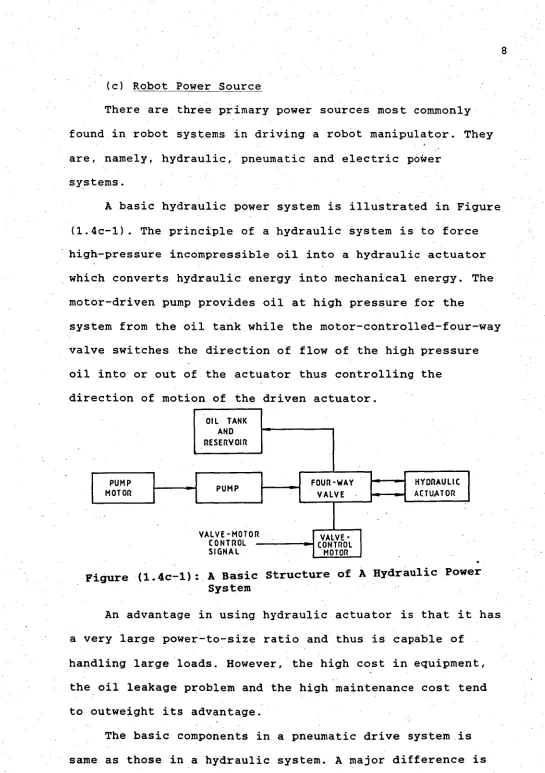
A basic hydraulic power system is illustrated in Figure (1.4c-1). The principle of a hydraulic system is to force
• high-pressure incompressible oil into a hydraulic actuator which converts hydraulic energy into mechanical energy. The motor-driven pump provides oil at high pressure for the
system from the oil tank while the motor-controlled-four-way valve switches the direction of flow of the high pressure oil into or out of the actuator thus controlling the
direction of motion of the driven actuator. OIL TANK
AND RESERVOIR
PUMP
MOTOR PUMP FOURVALVE-WAY
HYDRAULIC ACTUATOR
••••••-••••.
.11-•■ ■ ■
VALVE-MOTOR CONTROL
SIGNAL
.
.
.
I
VALVE -CONTROLMOTOR
Figure (1.4c-1): A Basic Structure of A Hydraulic Power System
An advantage in using hydraulic actuator is that it has a very large power-to-size ratio and thus is capable of
handling large loads. However, the high cost in equipment, the oil leakage problem and the high maintenance cost tend to outweight its advantage.
[image:16.559.5.550.16.789.2]that power is being transferred by gas, usually air, under pressure rather than by oil. An obvious advantage of this system over a hydraulic system is that system leakage does not cause contamination problem to the work area. Also, the total cost for a pneumatic system is less than that for a hydraulic system. However, using pneumatic drive system presents difficulties in achieving feedback control to
provide proportional operation and multiple stops due to the properties of the compressed gas. Therefore, in most
pneumatic robots, the acutators are driven against fixed stops at extremes of travel.
The electric system includes a source of electrical power and an electric motor. In most applications, the motors used are servo motors, but stepper motors are also used in some robots where the payload is small. A major disadvantage of stepper motors in robot applications
concerns the load torque to allowable speed characteristics of a stepper motor. The driving speed of a stepper motor, at large loads, cannot be too high; otherwise, loss of steps will result. This loss of steps cannot be detected and will result in permanent position errors. To allow variations -of load torque, the driving speed of a stepper motor is usually kept low. Consequently, the motion of the driven link is slow.
Servo motors are usually d. c., motors although a.c.
.motors are also used in some robot applications. An electric motor provides an excellent source of rotational torque
motion can also be achieved by using ballscrew drive which is analogous to bolt-and-nut operation. The advantages of servo motors, particularly d.c. motors, are their excellent speed regulation, high torque and high efficiency and are therefore ideally suited for control applications.
1.5 TEACHING METHODS
In general, a robot computer in a robot system involves a control program and a task program. The control program is provided by the robot designer to control each joint of the manipulator. The task program is provided by the robot
operator to specify the required manipulator motions for a particular job.
The way of generating -a task program depends on the method of teaching or programming employed in a robot
system. There are two methods of teaching a robot: off-line programming and on-line programming.
(a) Off-line Programming
In off-line programming, the robot operator makes use of commands set by the robot designer to specify conditions for a job, such as required pOsitions and orientations of the end-effector, its velocity and acceleration for each specified point in space. The method is characterized by commands which inform the robot what to do, but the robot itself is not used during the programming stage.
This method provides a quick way in programming when the required Cartesian points in space are relatively easy to access and measure. In practice, however, specifying. orientations of the end-effector with respect to a work
piece can be tedious. Also, it is not easy to visualize the • necessary rotation for each wrist joint nor the work limit
of the manipulator. User-specified points may not be
accessible by the robot and thus have to be checked before a task path can be planned or executed. Moreover, in cases where the location of the robot manipulator is frequently changed, off-line method becomes undesirable.
• (b) On-line Programming
Teach-by-showing is referred to as on-line programming and the robot itself is used during the programming stage.
During the programming stage, the operator moves the robot arm through a set of required points or a desired path in space by means of some teaching aids such as a teaching pendant, a control handle or a joystick. When a required point is reached, the operator presses a memory button and the system will 'remember' the joint coordinates at that instant. These joint coordinates are normally recorded so that the robot will aware of its physical working environ-ment and avoids collision with obstacles during the execut-ion of a task.
The additional teaching aid required for robot systems using on-line programming may seem to be a disadvantage but the software required during the programming stage is far simpler than that required by off-line programming method . Besides, critical points are easily realized by operator during teaching stage. Depending on the teaching aid employed, on-line programming can be subdivided into individual-joint teaching or lead-through teaching.
(i) Individual-joint Teaching
In individual-joint teaching, a teaching pendant
(teaching box) is used. The pendant consists of push buttons and teaching is done by pressing appropriate buttons to
rotate each joint of the robot until the combination of all joint positions and orientations yields the desired position and orientation of the end-effector in space. Then the
operator stores the joints coordinates of the robot at that instant by pressing a memory button. The process is repeated for each required point in space until the task program is completed. This teaching method demands patience in adjust-ing all joint axes, one by one, every time in givadjust-ing a
required point setting of the end-effector in space. A large amount of time is thus normally required in teaching the robot.
There are also teaching pendant which, instead of controlling a number of joint positions separately, can directly manipulate the position and orientation of the end-effector in space. During the teaching stage, the tool tip of the robot can be moved in a straight line and rotated about fixed axis in space. Although this solves the probfem of adjusting one joint axis at a time, the software required for this type of teaching pendant is more complicated and involves lengthy mathematics for required transformations from Cartesian to joint coordinates and vice versa. The resulting motion is, therefore, usually very slow.
(ii) Lead-through Teaching
A better way of teaching a robot is perhaps by grasping the robot's end-effector, leading it through a desired path,
13
and simultaneously recording the joint positions at desired points. Although teaching aid is not required in this method while the same robot arm is used for teaching, the fact that large forces are required to move the arm against its
driving and transmission elements prevents this method from being ideally used in practice.
A better approach is to use a teach arm which is similar to the actual manipulator but with far simpler structure. A teach arm may be equipped with position
CHAPTER TWO
THE TASROBOTO SYSTEM
The TasrobotO system is the first robot arm system built in University of Tasmania. Similar to most robot systems, it has three basic components: the robot
manipulator, the robot computer and the robot power source.
2.1 THE MANIPULATOR
The TasrobotO manipulator belongs to the class of
revolute coordinate robot and has five axes of rotation. The end-effector of the manipulator is a permanently attached open/close gripper with two movable jaws. The arm has three-degree-of-freedom for positioning and two-three-degree-of-freedom for orientating the gripper with respect to a work piece.
(a) The Arm
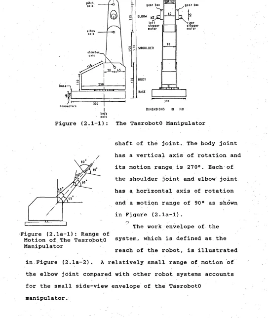
Positioning of the gripper is controlled by motion of three revolute joints which are denoted as body joint, shoulder joint and elbow joint. These three joints connect four links of the manipulator to form the major physical structure of the manipulator. The four links are denoted as base, body, shoulder and elbow as shown in Figure (2.1-1).
The motion of each joint is provided through direct gearings by an actuator which is a permanent magnet d
motor. The position of each of the three joints is indicated by a position transducer mounted on respective rotating
I body axis
DIMENSIONS M MI roll axis
f•J
gear box
right stepper motor GRIPPER
ELBOW
SHOULDER gear box
lett stepper motor
300 BODY
BASE
-Figure (2.1a-1): Range of Motion of The TasrobotO Manipulator
Figure (2.1-1): The TasrobotO Manipulator
shaft of the joint. The body joint 15
has a vertical axis of rotation and its motion range is 270°. Each of the shoulder joint and elbow joint has a horizontal axis of rotation and a motion range of 900 as shOwn in Figure (2.1a-1).
The work envelope of the system, which is defined as the reach of the robot, is illustrated in Figure (2.1a-2). A relatively small range of motion of the elbow joint compared with other robot systems accounts for the small side-view envelope of the TasrobotO
[image:23.563.19.562.173.817.2]• 0
ZEOR POSITION
ME
11
.11
11
1
1
Aa k
II
11
AdirC Orse-
II/
SCALE : 1 mm= 10 mm
0
(a) TOP VIEW
SCALE: 1 mm =10mm
(W SIDE VIEW
Figure (2.1a-2): Work Envelope of The TasrobotO Manipulator
[image:24.560.21.552.18.751.2](b) The Wrist
The wrist of the TasrobotO manipulator consists of two axes of rotation for control-ling the orientation of the
17
STEPPER
MOTOR gripper with respect to a work GEAR
MX
•
•
- - PITCH MS piece. Two stepper motors are STEPPERMOTOR GEAR BOX .
used to give pitch and roll rotations as shown in Figure
(2.1b-1). The lack of yaw rotation does not allow the GRIPPER
o
I
•
ROLLAXIS gripper to reach objects not Figure (2.1b-1): Gearings For aligned with the arm.
The Wrist Rotation
Pitch rotation is achieved by rotating the two stepper motors in same direction. Roll rotation results when the two stepper motors are stepping in different directions. The range of motion for roll rotation is physically unlimited, while the range of motion for pitch rotation is limited to
1400 as shown in Figure (2.1a-1).
(c) The Gripper
The end-effector of the TasrobotO manipulator is a gripper. It consists of two jaws, each of which is a two-bar-linkage structure. Normally, the jaws are closed by the action of a compression spring and can be opened by pulling against the spring. The pulling force is provided by a dc . motor with gearings. The whole conceptual structure of the
gripping system is illustrated in Figure (2.1c-1).
GRIPPER DRIVING UNIT
STOP -ER' - - FIXED ENDI OF THE STEED
STRING I• STEEL STRING • I
GRIPPER TWO BAR LIN • E 100416
MOVING HEAD CONNECTING
ROD ROTATING
SHAFT
• COMPRESSION
SPRING TWO BAR LINKAGE
JAW Iii
RIPPER MOTOR
to pass through all links of the manipulator and the
effective length of the steel string has to depend on the configuration of the arm. As a result, the amount of
rotation required for the gripper motor to rotate to open or close the gripper depends on the configuration of the arm.
Figure (2.1c-1): Conceptual Structure of The Gripping System
A position transducer is used to record the amount of rotation required for opening the gripper in a specific arm configuration awared during the teaching stage. The shaft position for the gripper to be fully closed is assigned in such a way that the effective length of the steel string is long enough for the gripper to stay closed in any arm
configuration. However, an attempt to drive the arm with a fully open gripper may result in closing or further opening of the gripper. Although the former causes no serious
problem, further opening of the gripper will cause damage to the gripper or even the arm as the force resulted from the tension of the steel string acts on the joints of the
•manipulator.
In normal operation, the gripper will remain closed unless instructed to open when comes to a target object.
Therefore, the change of arm configuration is usually small during the period when the gripper is open. Moving the
manipulator with an open gripper has been dealt with in
designing software control and the possibility of' occurrence of previously mentioned cases are eliminated.
2.2 THE ROBOT COMPUTER
(a) The Host Computer
The host computer for the TasrobotO system is an IBM/PC microcomputer. The computer uses an intel 8088 16-bit micro-processor and a 4 MHz clock. The computation speed of the host computer is greatly improved by installing the intel 8087 arithematic co-processor. It is also equipped with a commercially available interfacing board called Lab-Master Board provided by the Scientific Solution Inc.. In addition to the conventional analog-to-digital converter (ADC) and digital-to-analog converter (DAC), the Board provides timing signals through the AM9513 System Timing Controller and
digital interface through the 8255 Programmable Parallel Port Interface (PPI).
The board can be programmed by using the accompanied software package - the Labpac Subroutines - from the Tecmar Inc., which are specially written to handle the hardwares in the Lab-Master Board. However, the Lab-Master Board provides only two channels for D/A conversion, which are obviously not enough to control the five axes motion of the
manipulator; hence, part of the hardware interface were designed and built. -
The Labpac software provides only 16-bit input and 8- bit output in ,the digital-to-digital interface subroutines and cannot be used for controlling the additional hardwares. Software interfacing subroutines in 8088 assembly 'language were developed to control the addition hardwares and to provide special functions in manipulator control. These subroutines will be discussed in Chapter 7.
(b) The Controller Unit
In the controller unit, two types of controllers, servo and non-servo, are used. Here, the positioning of the joints and the gripping action of the gripper are monitored by the command signals recieved from the host computer.
Three position feedback controllers are used in the controller unit for controlling the positions of the three joints. Trading off with its simpler circuitry and much lower price, position feedback controller has disadvantage of no control in the motion velocity of the joint and will result in a basically point-to-point robot.
The gripper controller is classified as non-servo. The feedback signal from the gripper motor does not go directly into the controller itself, instead, it is sampled by the host computer which then generates suitable commands t control the gripper motor as shown in Figure (2.2b-1). The overall control of the gripping action is however closed-loop, although it appears to be open-loop in the controller unit.
Command signals from the host computer, controlling the gripping action, consists of two bits. The controller will
HOST COMPUTER
command
signals JOINT CONTROLLER
JOINT - MU M
react to these two bits to turn the motor on in one or the other direction or to turn the motor off.
21
command
HOST signals GRIPPER Grump COMPUTER CONTROLLER wmm
POSITION FEEDBACK POSITION FEEDBACK
Figure (2.2b-1): Control System of (a) Joint (b) Gripper
The pitch and the roll rotations are provided by motion of two stepper motors as shown in Figure (2.1b-1). Positions of the two wrist rotation axes are absolute provided that the robot arm is properly set to the reference position
before commencing. Command signals for each axial motion are position codes of 12 bits. Although there is no feedback signal in the wrist controller, its principle of operation is similar to servo type controllers in which the axial motion depends on the resulting error signal.
The feedback signal for each wrist axis is provided by a 12-bit counter which acts as a dynamic memory device and stores the previous position of that wrist axis in code. The magnitude of the error signal generates the number of
clocking pulses required to move the current position of the wrist joint to a desired position while the sign of the
error signal controls the direction of rotation of the
motion. Clocking signals for driving the stepper motors are also used to renew the counters simultaneously.
22
of the counters can represent the positions of the wrist joints, the wrist joints must be moved to pre-defined
positions, called reference positions, and the contents of the counters must be assigned pre-defined values, called reference codes, corresponding to the reference positions. Since there are no sensors mounted on the actual rotating shafts of the wrist joints, the computer cannot identify the reference positions. The reference positions of the wrist joints will have to be set manually before setting the contents of the counters. When the reference positions and reference codes are set, the counters will function like absolute shaft encoders of the two rotating wrist axes provided no loss of steps of the stepper motors occurs.
Since the two stepper motors must be energized to perform one axis of rotation, the controller unit is
designed so that only one axis of rotation is implemented at a time.
2.3 POWER SOURCE
The power source of the TasrobotO arm are electric
actuators. There are four permanent magnet dc motors and two stepper motors.
Three of the dc motors are used to drive the position-ing joints and the other is to provide grippposition-ing action. The high speed but low torque characteristics of dc motors does
• not make them prevalent for driving loads directly. In
practice, higher driving torque is achieved by trading off the high speed of the motor through speed reduction
MEMORY SWITCH
times that developed from motor, but the driving speed is reduced to 1/N times the motor speed.
The stepper motors used are 7•50 stepper motors each having four 12V dc windings and permanent magnet rotor construction. Each motor is equipped with a gear box which reduces the output step angle to 0.6° and decreases the maximum step rate to about 20 steps/sec (or 12°/sec) to achieve a maximum output torque of the motor.
2.4 PROGRAMMING THE TASROBOTO MANIPULATOR
The programming of the TasrobotO manipulator is done through the use of a teach arm as shown in Figure (2.4-1).
POTENTIOMETER
FOR ELBOW AXIS In teach mode, the
POTENTIOMETER
FOR PITCH AXIS configuration of the actual
OW SWITCH arm will follow that of the POTENTIOMETER POTENTIOMETER
FOR SHOULDER FORROLLMS teach arm. Therefore, grasping
AXIS
the end-effector of the teach
FOR BODY AXIS
1Figure (2.4-1): The Structure of The Teach Arm of The TasrobotO System
actual arm, better still, the teach arm can easily be moved to take any configuration. Desired configuration of the actual arm can be recorded by pressing a memory switch located at the end-effector of the teach arm.
There are five potentiometers and two microswitches in the teach arm. One potentiometer is installed in each
rotating joint to indicate the position of that joint. The GRIP-switch is to signal the robot computer to open or close the gripper. The MEM-switch is to signal the robot computer to record the current joint coordinates.
23
POTENTIOMETER
During teaching stage, the robot computer samples
signals from sensors on the teach arm and drives the actual manipulator accordingly at the same time. The GRIP-switch has two functions. Not only does it tell the computer to open or close the gripper of the actual arm, it also allows the user to indicate how much the gripper motor must be turned to open the gripper in a specific arm configuration with respect to how long the GRIP-switch is held pressed.
Programming a robot for a task using a teach arm is simple and convenient since the operator does not need to measure the Cartesian coordinates in space as required by off-line programming, nor to worry about the position of each individual joint of the robot as required in manual teaching using teach pendant. In addition, the control program for the teaching process is much simpler as no mathematics for coordinate transformations are required.
CHAPTER THREE
HARDWARE DESIGN OF THE TASROBOTO CONTROLLER UNIT
The hardwares for the controller unit consist of three printed circuit boards (PCBs) and a power rectifier unit. The three PCBs are identified as the analog control board, the digital control board and the interface circuit board.
The analog control board mainly controls the analog devices, i.e. the four dc motors of the manipulator. The digital control board controls the two stepper motors. And the interface circuit board provides communication between the control boards and the host computer. The dc power required by each board is provided by the rectifier unit which converts 240V ac mains power to unregulated dc
voltages of ±20V and +11V. Regulated dc power required by active components used on each board is provided by its onboard regulators. Figure (3-1) illustrates a schematic structure of the TasrobotO controller unit.
The complete circuit diagrams for the controller unit with pin-to-pin configurations are shown in Appendix A. The designed ciruits were built and used as the control hard-Wares of the TasrobotO system.
3.1 THE ANALOG CONTROL BOARD
The analog control circuit was designed to control the four dc motors driving the TasrobotO manipulator, three of which control the motion of the three positioning joints and
26
A. C. MAINS SUPPLY
POWER RECTIFIER
UNIT
20 V
- GN
2 0 V . 11 V - G ND
BODY ACTUATOR SHOULDER ACTUATOR ELBOW ACTUATOR OR MOTOR BODY REFERENCE
SHOULDER RE FE RENCE
ELBOW REFEREKE
GRIPPER SIGNALS CONTROLLEROPEN LOOP
.21V
-
r
.111V BODY.2rir / I ND
SHOULDELL ELBOW GRIPPFU
GRIPPER.] ANALOG
CONTROL -BOARD
BODY ACTUATOR -. SHOULDER ACTUATOR
ELBOW ACTUATOR
}GRIPPER MOTOR
FROM 16 HOST COMPUTER
INTERFACE CIRCUIT
BOARD co 5 12 GND 40VM V
12
1
1
DIGITAL CONTROL
-11 LEFT --.J SMTOETPOPRE R
AME
I R MOTORFigure (3-1) : Schematic Diagram of The TasrobotO Controller Unit
one controls the gripping action of the two-jaw gripper. The former are closed-loop control while the latter is closed- . loop control via the host computer. Figure (3.1-1)
illustrates a schematic layout of the board. 'BOARD
PITH
ROLL
BODY FEEDBACK
SHOULDER FEEDBACK
ELBOW FEEDBACK
GRIPPER FEEDBACK TO COMPUTER
ANALOG CONTROL BOARD
-
CLOSE-LOOP
CONTROLLER.
r
---- - - _ _ _ - - - - ---
DIFFERENTIALI POWER
AMPLIFIER COMPENSATNETWORKION AMPLIFIER ACTUATOR
vRE F 2
Figure (3.1a-2): An
Instrumentation Amplifier
Figure (3.1a-3): The Compensator Circuit
v0
1
V02
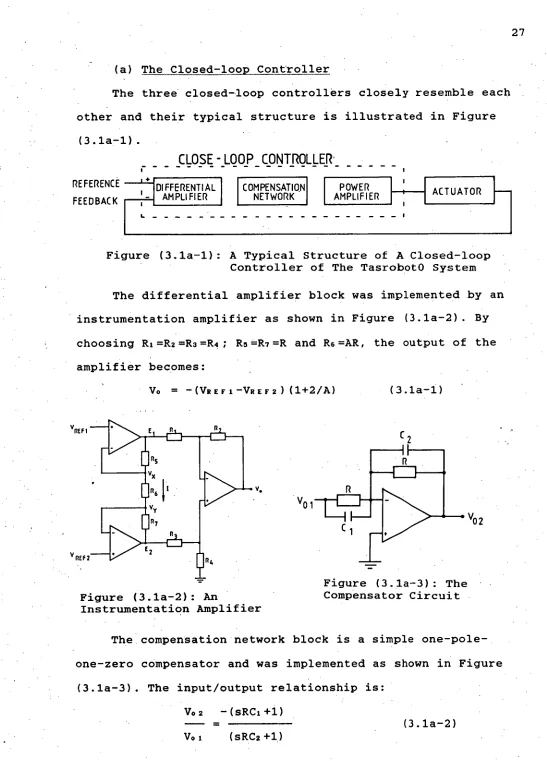
(a) The Closed-loop Controller
The three closed-loop controllers closely resemble each other and their typical structure is illustrated in Figure
(3.1a-1).
27
REFERENCE FEEDBACK
Figure (3.1a-1): A Typical Structure of A Closed-loop Controller of The TasrobotO System
The differential amplifier block was implemented by an instrumentation amplifier as shown in Figure (3.1a-2). By choosing RI=R2=R2=R ; R5=R7=R and R5=AR, the output of the amplifier becomes:
Vo = -(V2EFI-V2Er2)(1+2/A) (3.1a-1)
The compensation network block is a simple one-pole-one-zero compensator and was implemented as shown in Figure
(3.1a-3). The input/output relationship is: V02 -(sRC1+1)
(3.1a-2)
[image:35.558.11.558.25.786.2]1K
OUTPUT (to actuator) • INPUT
( from compensator R3 circuit output ) 1K
C 3 I 0.24F -Vcc
The power amplifier block was implemented by a type 165 Power Op-amp and the circuit is shown in Figure (3.1a-4).
Figure (3.1a-4): A Power Op-amp Circuit Using Type 165 Op-amp
These three circuits form the closed-loop controller for the positioning joints of the TasrobotO manipulator.
(b) The Open-loop Controller
The gripper motor is controlled in closed-loop via the host computer. Command signals from the host computer
directly control the motion of the gripper motor. A 2-bit signal is used for controlling the three possible states: rotating forward, backward or stop. The implementation of the control scheme merely requires a suitable power
amplifier to drive the motor correspond to the 2-bit command signal.
The control circuit for the gripper motor is shown in Figure (3.1b-1). A general purpose light emitting diode
(LED), with a voltage drop of about 2V across, was used to provide reference to the 2-bit TTL command signal from the host computer. A gain of 10 in each amplifier allows the
output to be pulled up to its maximum or minimum saturation voltage, thus enabling higher initial torque and faster operation of the motor.
10 K 10 K
29
LED
Figure (3.1b-1): The Gripper Control Circuit
Table (3.1b-1) summarizes the action of the gripper in relation to the status of the two command signals (BITO and BIT1).
BIT. BIT1 GRIPPER MOTOR GRIPPER JAWS 0 0 UNENERGIZED NO ACTION 0 1 CLOCKWISE ROTATION OPENING JAWS
0 ANTICLOCKWISE ROTATION CLOSING JAWS 1 1 UNENERGIZED NO ACTION
Table (3.1b-1): Actions of Gripper Motor And Gripper Jaws With Respect To The States of The 2-bit Command Signal
3.2 THE DIGITAL CONTROL BOARD
The digital control circuit was designed to control the two stepper motors which drive the two wrist rotations of the TasrobotO manipulator. The control schemes for the two wrist rotations are similar in structure and is illustrated in Figure (3.2-1).
'Unlike the dc servo motor controller, the wrist
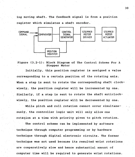
ing moving shaft. The feedback signal is from a position register which simulates a shaft encoder.
COMMAND CONTROL STEPPER STEPPER
SIGNAL COMPARATOR SIGNAL MOTOR MOTOR GENERATOR DRIVER ACTUATOR
POSITION REGISTER
Figure (3.2-1): Block Diagram of The Control Scheme For A Stepper Motor
Initially, this position register is assigned a value corresponding to a certain position of the rotating axis. When a step is sent to rotate the corresponding shaft clock-wisely, the position register will be incremented by one. Similarly, if a step is sent to rotate the shaft anticlock-wisely, the position register will be decremented by one.
While pitch and roll rotation cannot occur simultane-ously, the controller logic unit will only allow one
rotation at a time with priority given to pitch rotation. The control scheme can be implemented by software technique through computer programming or by hardware technique through digital electronic circuits. The former technique was not used because its resulted wrist rotations are comparatively slow and hence substantial amount of
computer time will be required to generate wrist rotations. Also, during such wrist rotations, the computer would not be able to generate commands for motion of the other joints; and very slow overall motion of the manipulator will be expected. Although software technique was not used, the flow-chart of the control algorithm shown in Figure (3.2-2)
[image:38.559.4.546.30.660.2]DECREASE PITCH POSITION REGISTER BY ONE READ PITCH POSITION
COMMAND SIGNAL
PITCH PITCH COMMAND >POSITION ?
IGNAL REGIST
PITCH PITCH COMMAND< POSITION ?
IGNAL REGIST
ROTATE PITCH AXIS CLOCKWISELY BY ONE STEP INCREASE PITCH POSITION REGISTER BY ONE Y ROTATE PITCH AXIS
ANTICLOCKWISELY ST
ROTATE ROLL AXIS CLOCKWISELY BY ONE STEP
H
INCREASE ROLLPOSITION REGISTER BY ONE
ROTATE ROLL AXIS ANTICLOCKWISELY BY N ST P DECREASE ROLL POSITION REGISTER BY ONE •
ROLL ROLL COMMAND > POSITION ?
IGNAL REGIS
ROLL ROLL COMMAND < POSITION ?
GNAL REGIS!' POSITION REGISTERS
READ ROLL POSITION COMMAND SIGNAL
helps illustrating the hardware design of the control scheme.
Figure (3.2-2): Flow-chart of The Wrist Control Algorithm
In the implementation of the stepper motor control scheme, the control blocks shown in Figure (3.2-1) were replaced by hardware functional blocks shown in Figure
(3.2-3).
Since a step angle for the stepper motor is 0.6°, a minimum of 600 discrete levels or a 10-bit decoder is required to unambiguously represent the position of the wrist joint shaft. In this design, a 12-bit decoder was used to provide greater adaptability of the circuit. For example, if the step angle is now changed to 0.09° to
provide larger output torque, about 6 times that of 0.6°, the same circuit can be used without modification.
LOAD REFERENCE DATA SIGNAL
32
1
)
ITCH iparalle load 9 ,-•-4 2
‘. i 12-BIT UP/DOWN 1=1 COUNTER
- out :1424-"I a -a 12 -BIT PITCH COMMAND 12
12 - BIT ROLL COMMAND
12 .
inputs B 9? 12-BIT
MAGNITUDE 4 UM W/UM 12 -BIT MAGNITUDE COMPARATOR inputs B
f
_
,
.
.
]
r
i
12-BIT UP/DOWN : : outputs 0 COUNTER _. a-.
> Parallel load ri Ln as CO NT RO L LO GI C UN IT ■- ■
-4. LEFT STEPPER a MOTOR DRIVE LEFT STEPPER MOTOR MOT B. STEPPER
MOTOR DRIVE 56. RIGHT STEPPER MOTOR on C9-1- 'ROLL
LOAD REFERENCE DATA SIGNAL
Figure (3.2-3): Hardware Block Diagram of The Digital Control Scheme
The position register block in the control scheme was implemented by a 12-bit Up/Down counter. Command data from the host computer is compared with the counter output, the latter represents the shaft position of the corresponding wrist joint. Compared results were used to signal the
control logic unit to generate appropriate signals to drive the stepper motors and to update the counters. The control logic unit also distinguishes pitch or roll rotation and gives priority to the former.
(a) The 12-Bit Comparator
Two 12-bit comparators are required, one for each wrist rotation. Each comparator was implemented by cascading three 74C85 4-bit magnitude comparators and is illustrated in
3 BIT COMPARED RESULTS TO CONTROL LOGIC UNIT
GT EQ LT / A)13 A=B AB
A3 .3
74C85
1 B1
0 BO
AB A=B MB
I
I
I
MB A=B MBA3 B3
A2
74C85
82
A1 B1 AO BO AB A=B A.B A)B A=B AB A3 B3 A274C85
B
2
At B1
Ao Bo
MB A=B AiB ±
33
• 11
•12-BIT DATA < • FROM HOST COMPUTER
• • •
(11
12-BIT DATA FROM COUNTER
+ 5V
Figure (3.2a-1): A 12-bit Magnitude Comparator
(b) The 12-bit Up/Down Counter
'The control scheme requires two 12-bit up/down count-ers, one for each wrist rotation. The counters act like position indicators of the current shaft positions. Pulses generated to move the stepper motors also update the
counters in such a way that the counter outputs will be
. CP .•
• 0/D
r
i
l
i
FLD3 Q3
74LS191 c/2
Di 1 Q1_..c.1
0 Do D O —Co D _
(P
Um
rTC
P
I
D3 D3
0274L5191 Q2 D1 Q1 Do Q0
LOAD REFERENCE DATA "LOAD SWITCH
UM LT—. D11 03 Q3 C11
Dz743191 QQ12
oo ao
•
34
12-BIT DATA FROM HOST COMPUTER
12-BIT DATA TO COMPARATOR
UD CLK
FROM CONTROL LOGIC UNIT
Figure (3.2b-1): A 12-bit Up/Down Counter
(c) The Stepper Motor Driver
A suggested stepper motor driver IC for the stepper motor is the SAA1027. A typical circuit for the driver is shown in Figure (3.2c-1). A Low-to-High transition on the STEP pin turns the motor by one step. The sequence of output signals and the direction of rotation of the motor depend on the signal level of the Direction pin (DIR).
FROM STEP CONTROL
LOGIC
UNIT DIR
STEPPER MOTOR
+12V
Figure (3.2c-1): Circuit Diagram For The Stepper Motor Driver SAA1027
(d) The Control Logic Unit
The control logic unit is the heart of the control scheme. It generates TTL logic level voltages to update the counters. It generates appropriate logic level voltages to control the stepper motor drivers in driving the stepper motors, with respect to the six resulting signals from the two comparators. The six input signals are arranged in two groups of three, one group from one comparator.
. There are four pairs of output signals in the control logic unit. Each pair of output signals consists of a
clocking signal and a direction control signal. Two pairs of output signals are TTL logic level voltages for controlling the two 12-bit counters. The other two pairs of output
signals are special logic level voltages for controlling the two stepper motor drivers. Figure (3.2d-1) shows the sources of the input signals and the destinations of the output
signals. The symbols used in the figure will carry their meanings throughout the rest of this section.
Figure (3.2d-1) also illustrates the internal structure of the control logic unit. Functionally, the unit can be
PITCH CONTROL ROLL CONTROL
12- BIT COMPARATOR
GT EQ IT
D2 C1 02 Ui P1
divided into three parts, namely, the clock generator, the pulse generator and the direction signal generator.
•The clock generator outputs a continuous TTL clock signal with a constant frequency. This clock signal is fed into the pulse generator to provide clocking signal to the two counters and the stepper motor drivers. The clocking frequency is about 20Hz providing maximum working torque for the motors. The direction signal generator generates
appropriate signals to up-count or down-count the counters and to rotate the stepper motor in either directions.
36
ONTROL LOGIC UNIT CLOCK GENERATOR
PULSE Pi GENERATOR
- r--•••• STEP
STEPPER MOTOR CONTRO LEFT
STEPPER MOTOR DRIVER
RIGHT STEPPER
MOTOR DRIVER STEP D R STFP rR
- --- STEPL R L STEP R DIR
E1 03
DIRECTION SIGNAL GENERATOR
DO Ul MRR MRL
Figure (3.2d-1): Block Diagram of The Input Sources And Output Destinations of The Control Logic Unit
Dl-
(i) The clock generator
The clock generator of the control logic unit is a free-running multivibrator as illustrated in Figure
(3.2d(i)-1).
With R1=R2=R4=R; R5>>R5 and R5<<R, the frequency of oscillation fooc can be shown as:
Resistor R3 was selected as 22k and C. as 1.5pF, and the
resultant frequency of oscillation is about 22Hz.
37
R 3
R5
8 LM311
1
vo
R4
Figure (3.2d(i)-1): The Clock Generator Circuit
(ii) The pulse generator
The main functions of the pulse generator are to
provide non-TTL signal, STEP, to the stepper motor drivers
to drive the stepper motors; and to provide TTL signals, PO
and Pi, to activate the counting function of the two counters.
The non-TTL signal, STEP, will be activated unless both
•the EQ signals from the two comparators are high. Therefore,
only the input signals, Eo and El, of the control logic unit
are required to implement clocking control of the stepper motors.
The clocking source of the pulse generator is the clock generator. By enabling or disabling the clocking source, the
outputs of the pulse generator, Po and Pl, will activate or
INPUTS OUTPUTS E•0 E 1 CLKI PO P1 STEP
0 0 0 0 1 0 0 0 1 1 1 1 0 1 0 0 1
1 1 1
0 0 1 1 1 1 1 1 0 0 1 0 0 1 0 1 1 1 1 1 1 0 1 1. 1
1
NOTE:
0 =LOW LOGIC LEVEL 1 -HIGH LOGIC LEVEL
• HIGH LOGIC LEVEL IS • 12 V AND LO W LOGIC LEVEL IS 0 V ..CLK IS THE SIGNAL FROM THE
OUTPUT OF THE CLOCK GENERATOR
'O
t
00
01
11
10
0
1
010
010
111
100
111
1
11
111
111
[STEP R
STEP L 10K
counter, PI, will only be enabled when the specific pitch
rotation has completed.
Figure (3.2d(ii)-1): Karnaugh Map For The Table (3.2d(ii)-1): Truth Table, Output Signals PoPISTEP,
•For The Outputs of The Pulse of The Pulse Generator
Generator
The required truth table for the signals Po, Pi and STEP is shown in Table (3.2d(ii)-1). The karnaugh map for the output signals is illustrated in Figure (3.2d(ii)-1). The logical expression for each output is:
Po = Eo+CLK (3.2d(ii)-1)
PI = gO+El+CLK (3.2d(ii)-2)
STEP = E0El+CLK (3.2d(ii)-3)
The circuit for the pulse generator is shown in Figure (3.2d(ii)-2).
CLK pULSE GENERATOR
Po
PI •12V Ei
38
r"-
po
..
(iii) The direction signal generator
The direction signal generator provides two types of signals: non-TTL type signals, DIRL and DIRR, to control the type of rotation, pitch or roll, as well as its direction; and TTL type signals, Uo and Ul, to control the counting direction of the counters.
39
INPUT • -SHAFT
AXIS DIFFERENTIAL
GEARINGS
E F-- = =r411)irn , e r=7 1= 1 0
‘a INPUTLEFT LEFT SHAFT MOTOR
OUTPUT SHAFT
OUTPUT SHAFT
AXIS
Figure (3.2d(iii)-1): Motions of The Input Shafts And The Output Shaft of The Wrist
INIATTSHAFT
MOT ION INIRIFSVIAFTMOTION OUTPUT SHAFT MOTION L1 R 1 PITCH CLOCKWISE
R 2 ROLL CLOCKWISE RI ROLL ANTICLOCKWISE I. •2 R2 PITCH ANTICLOCKWISE
Table (3.2d(iii)-1): Types And Directions of Motion Referring to Figrue(3.2d(iii)-1)
RIGHT RIGHT INPUT STEPPER SHAFT
MOTOR
The axes of rotation of the two stepper motors are aligned in one axis with differential gearings as shown in Figure (3.2d(iii)-1). Two non-TTL signals, DIRL and DIRR, from the direction signal generator, control the two stepper motor drivers. With two possible directions of motion for each motor, the output shaft has four different types of resulting motion. Taking Li, L2, RI and R2 to be the
directions of motion of the two input shafts as shown in Figure (3.2d(iii)-1), the resulting motion of the output shaft is shown in Table (3.2d(iii)-1). The definitions of directions of pitch and roll rotations are shown in Figure
ELBOW \ . Ilk \ •
.CLOCISMg_."-"\ATCH ROTATION ANTICLOCKWISE
GRIPPER
The additional requirement to give higher priority to pitch rotation is achieved by generating the two direction control signals, DIRL and DIRR, for pitch rotation first.
•40
ROLL ROTATION
DIR L DIR R WRIST MOTION
. 0 0 PITCH CLOCKWISE
0 1 ROLL CLOCKWISE
• 1 0 ROLL ANTICLOCKWISE 1 1 PITCH ANTICLOCKWISE
t-P
r-A
Figure (3.2d(iii)-2): Definitions of The Wrist Rotations
Table (3.2d(iii)-2): Wrist Rotations With Respect To The Direction Control Signals
The truth table for the signals DIRL and DIRR is shown in Table (3.2d(iii)-3). The karnaugh maps for the two
signals DIRL and DIRR are shown in Figure (3.2d(iii)-3); and the logical expressions for the two signals are:
DIRL = Do +I5iD2 (3.2d(iii)-1)
DIRR = Do +D3
E
(3.2d(iii)-2)
Two TTL type signals, Uo and Ul, are generated by the direction signal generator for controlling counting direct-ion of the two counters. Unlike the non-TTL signals, Uo and Ul are not governed by the priority requirement. This allows
the signals Uo and Ul to be generated in a simpler scheme as:
Uo = DI (3.2d(iii)-3)
(3.2d(iii)-4)
The overall circuit diagram for the direction signal•
00 01 11 10
1 X 0
1 1 X 0 X X X X
0 1 X 0
00 01 11 10
X l x
0 1 X 0
X X •X X
1 X 0
(b)
Figure (3.2d(iii)-3): Karnaugh Maps For (a)DIRL Signal And (b)DIRR Signal
0 7
0 0. 0 1 0 0 00 01 11 10 D3
NAND gates are used to provide non-TTL signals, DIRL and DIRR, with a high level of +12V and a low level of OV.
P3 D2 01 DO DIRL DIRR REMARKS
0 0 0 0 X X BOTH ROTATIONS COMPLETED 0 0 0 1 1 1 PITCH ANTICLOCKWISE ROTATION 0 0 1 1 0 0 PITCH CLOCKWISE ROTATION 0 0. 1 1 X X DO NOT OCCUR
0 1 0 0 1 0 ROLL CLOCKWISE ROTATION
0 1 0 1 I 1 (PRIORITY) PITCH ANTICLOCKWISE ROTATION 0 1 1 0 0 0 (PRIORITY) PITCH CLOCKWISE ROTATION'
1 1 1 X X DO NOT OCCUR
1 0 0 0 0 1 ROLL ANTICLOCKWISE ROTATION 0 0 1 1 I (PRIORITY) PITCH ANTICLOCKWISE ROTATION 1 0 1 0 0 0 (PRIORITY) PITCH CLOCKWISE ROTATION 1 0 1 1 X X ,
1 1 0 0 X X
1 1 0 1 X X DO NOT OCCUR 1 1 1 0 •X X
1 • 1 1 X X NOTE: I'• = LOGIC HIGH LEVEL
" 0 = LOGIC LOW LEVEL X = DON'T CARE
Table (3.2d(iii)-3): Truth Table For The Control of The Wrist Rotations
41
•12 V
10K 10K
01
02 )3-
/ c> DIRL
Do
0/ c> DI RR
42
3.3 THE INTERFACE CIRCUIT BOARD
In the TasrobotO system, the major hardware interfacing was done by a commercially available interfacing board, the Lab Master Board, from the Tecmar Inc.. The board, located at addresses 0710H to 071FH, provides three major types of interface, namely, analog-to-digital, digital-to-analog and digital-to-digital interfaces. Each type of interface can be initiated by writing appropriate signals to its correspond-ing address shown in the manual[R 32 ]. Software subroutines written for the board were provided by a commercially
available package, the Lab-pac Subroutines, from the Scientific Solutions Inc.. Each of these subroutines was written for a specific function as described in the
manual[R 33 ].
The analog-to-digital interface of the Lab Master Board consists of an 8-bit multiplexer, giving 256 possible analog . input channels. The DAC installed has a resolution of 12
bits. With the aid of the Lab-pac Subroutines, the input channels can be sampled at regular intervals with maximum sampling frequency as high as lkHz. Regular sampling can be achieved by hardware interrupts generated by the System Timing Controller AM9513. All the analog input interfacing for the TasrobotO system was done through the Lab Master Board using Lab-pac Subroutines.
However, the Lab Master Board provides only two
is accessed through the data bus using the 8255 Programm-able Parallel Port Interface (PPI) in the Lab Master Board.
The digital-to-digital interface of the Lab Master Board is provided by the 8255 PPI. The PPI occupies four address locations, one for command register and three for data registers. There are 24 programmable input/output
channels in the PPI. The command register, located at 071FH, allows each of the 24 channels, which are arranged in three 8-bit ports: portA, portB and portC, to be programmed as either input or output channels. The input data or output data can be read or written through the data registers located at 071CH to 071EH for portA, portB and portC respectively.
PortA, the upper 8-bits of the 24 bits, was programmed as input port for manipulating digital input signals. At present, there are three one-bit digital input signals, one from the MEM-switch and one from the GRIP-switch, both
mounted on the teach arm. The third signal is from the +5V power supply rail so that the power supply for the
electronics in the TasrobotO controller unit can be examined.
PortB and portC which occupy the lower 16 bits of the 24 bits were programmed as output ports. Since there are six output devices, four dc motors and two stepper motors, to be controlled, six registers are required to latch data to
appropriate devices. The upper 4 bits of the 16 bits output from the host computer were used to initialize one of the six registers using a 3-to-8 decoder, and the lower 12 bits were used as data bits. The interfacing circuit of the
TasrobotO system thus consists of six 12-bit data registers, one 3-to-8 decoder and three DACs as shown in Figure (3.3-1)
4
INTERFACE CIRCUIT
12 • BOARD
>--- DAC>—*
-BODY COMMAND
SIGNAL
SHOULDER CO
IGMNMAALND S
ELBOW COMMAND
SIGNAL
WRIST /PITCH COMMAND 3: 8
DECODER ROBOT
HOST COMPUTER
1: 15-12D12
an-00 f
DATA REGISTER 12 DATA REGISTER DAC 12 DATA REGISTER DAC 11,9 12 JA.,1REGISTERDATA
11
SIGNAL
WRIST/ ROLL I DATA REGISTER 29 24.1 12 10 COMMAND SIGNAL
GRIPPER MOTOR CONTROL SIGNAL '
DATA REGISTER
SPARES
Figure (3.3-1): Layout of The Interface Circuit Board
(a) The Decoder and The Data Register Circuit
The 3-to-8 decoder and the six 12-bit data registers form the addresses of the output devices. Three of the data registers latch data for the three DACs to control the
positioning motion of the manipulator while the remaining three provide digital control on the stepper motors and the gripper motor. The data signals for the five joint motors are 12-bit. The gripper motor only requires 2-bit data signals and 10 bits are spare in its data register.
Of the 16 bits from the computer data bus, four bits are used to generate the chip-select-signals: three of which decode the address of the six output devices and one enables the decoder.
3:9 DECODER
12
Dll 015 from Di4 4 MSBs of data
bus 1
DATA REGISTER
from lower 12 -bit of the data b
+5v
i
clear CFK----' D6
n_ -t CI6 '-', to— as
04 ( 7) Q4 0 3-i --i- Q3 D2 r.- Q2
DI CI1
clear CLK
06 Q6
05 r- 05
04 c7; a4
C13 r--- Q2
Dl Q1
+5V
I I
Or,
12 -bit Latched output
Figure (3.3a-1): Decoder And A Data Register Circuit
Yo
The 74LS138 3-to-8 Decoder was used in the design. It decodes one-of-eight lines based on the conditions of the three binary select inputs: A, B and C; and the three enable
inputs: GI, G2 A and G2B. When the decoder is enabled, one of
the eight outputs is pulled down to low level according to the levels on the select inputs as shown in Table (3.3a-1).
Two 74LS174 Hex D Flip-Flops were used to form a data register circuit. Six registers are driven by the decoder,
all having similar circuits as shown in Figure (3.3a-1) but•
driven by different output of the decoder as indicated in 45
Table (3.3a-2).
INPUTS
OUTPUTS Naa uau
61 C B A YO Yi Y2 Y3Y4 `Ifsy6 y7
X X X H H H H H H H H H LL L L H H H H H H H L L H H L H H H H H H H L HL H HL H H H H H H L H H H H H L H H H H H HL L H H H H L H H H H H L H H H H H H L H H
H H HL HH HH L H
H.H H H H H H H H HL
NOTE: " H" • LOGIC HIGH " L " • LOGIC LOW " X " = DM T CARE
mAND Gm ARE HELD LW.
Table (3.3a-1): Truth Table of
The Decoder 74LS138
SELECTINPUTS OF DECODER OUTPUTENABLED
BA°""°c"
ENABLED DATA REGISTER
C
L LL Yo BODY
L L H yi WRIST/PITCH
L H L Y2 SHOULDER
L HH Y3 WRIST I ROLL
HL L V4 ELBOW
HL H Y5 GRIPPER MOTOR
H H L Y6 NOT USED H H H Y7
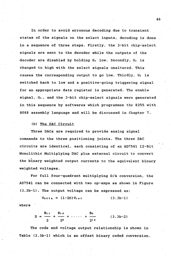
In order to avoid erronous decoding due to transient states of the signals on the select inputs, decoding is done in a sequence of three steps. Firstly, the 3-bit chip-select signals are sent to the decoder while the outputs of the decoder are disabled by holding GI low. Secondly, GI is changed to high with the select signals unaltered. This causes the corresponding output to go low. Thirdly, GI is switched back to low and a positive-going triggering signal for an appropriate data register is generated. The enable signal, GI, and the 3-bit chip-select signals were generated in this sequence by softwares which programmes the 8255 with 8088 assembly language and will be discussed in Chapter 7.
(b) The DAC Circuit
Three DACs are required to provide analog signal commands to the three positioning joints. The three DAC circuits are identical, each consisting of an AD7541 12-Bit Monolithic Multiplying DAC plus external circuit to convert the binary weighted output currents to the equivalent binary weighted voltages.
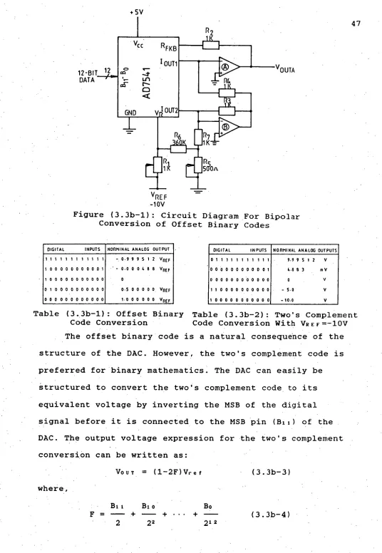
For full four-quadrant multiplying D/A conversion, the AD7541 can be connected with two op-amps as shown in Figure
(3.3b-1). The output voltage can be expressed as: VOUTA = (1-2D)Vrof (3.3b-1) where
46
Bil Bio
D = + +
2 22
Bo
(3.3b-2) 212
[image:54.562.3.550.0.817.2]+ 5V
R2
I
1K Vcc. RFKB 1IOUT1
0 .- ®
m - 4
-
-
E
4
R4 a-s- DLt-t-,- - 11(
12-BIT 12 DATA
v
OUTAGND I OUT2
R7 1K =
5 O.
VREF -10V
Figure (3.3b-1): Circuit Diagram For Bipolar Conversion of Offset Binary Codes
47
DIGITAL INPUTS NORMINAL ANALOG OUTPUT 111111111111 -.0•999512 VREF
100000000001 • ' - 0•000488 VRE.F
1 0 0 0 0 0 0 0 0 0 0 0 0
0 1 0 0 0 0 0 0 0 0 0 0 0.5 00000 VREF
0 0 0 0 0 0 0 0 0 0 0 0 1.0 0 0 0 0 0 VREF
DIGITAL INPUTS NORMINAL ANALOG OUTPUTS 011111111111 9.9 9 S 1 2 V
0 0 0 0 0 0 0 0 0 0 0 1 4.8 8 3 mV
0 0 0 0 0 0 0 0 0 0 0 0 0 V
1 1 0 0 0 0 0 0 0 0 0 0 -5.0 V
1 0 0 0 0 0 0 0 0 0 0 0 -10.0 V
Table (3.3b-1): Offset Binary Table (3.3b-2): Two's Complement Code Conversion Code Conversion With VREF=-10V The offset binary code is a natural consequence of the structure of the DAC. However, the two's complement code is preferred for binary mathematics. The DAC can easily be
structured to convert the two's complement code to its equivalent voltage by inverting the MSB of the digital signal before it is connected to the MSB pin (Bit) of the DAC. The output voltage expression for the two's complement conversion can be written as:
VouT = ( 1-2F)Vref (3.3h-3) where,
Bit Bi o Bo
F = — + — + • • • (3.3b-4)
[image:55.558.9.545.21.797.2]