Occlusion, transparency, and lightness
Marc K. Albert
School of Psychology, University of Southampton, Southampton SO17 1BJ, UK
Received 2 January 2007; received in revised form 13 April 2007
Abstract
The lightness of a visual surface is its perceived achromatic reflectance [Adelson, E. H., (2000). Lightness perception and lightness illusions. In M. Gazzaniga (Ed.),The new cognitive neuroscience(2nd ed.) (pp. 339–351) Berlin: Springer; Gilchrist, A. (1999). Lightness perception. In R. W. F. Keil (Ed.),MIT encyclopedia of cognitive science(pp. 471–472). Cambridge: MIT press]. Lightness ranges from black, through various shades of grey, up to white. Anderson and Winawer [Anderson, B., Winawer, J. (2005). Image segmentation and lightness perception.Nature, 434,79–83] suggested that perceptual decomposition of image luminance into multiple sources in different layers (e.g., perceptual transparency) is critical to the their lightness illusions. However, I show that simple perceptual occlusion evoked by T-junctions will work as well, suggesting that perceptual scission of luminance into multiple layers is unnecessary for such effects. I argue that the lightness illusions presented by Anderson and Winawer involve fundamentally different mechanisms than previously stud-ied lightness illusions, including those involving perceptual transparency.
Ó2007 Elsevier Ltd. All rights reserved.
Keywords: Lightness; Transparency; Surface perception; Occlusion; Visual perception
1. Introduction
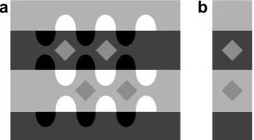
Adelson (1993, 2000)devised a variety of new lightness illusions that were stronger than any previously known. For example, the diamond-shaped targets in Fig. 1a all have identical image luminances, however the upper dia-monds appear much lighter than the lower ones. Adelson’s displays not only produce strong lightness illusions, they also evoke percepts of transparency, or percepts in which different targets appear to be under different levels of illu-mination. Thus, the upper diamonds inFig. 1a appear to lie behind a dark transparent strip, or in a region of dim-mer illumination than the lower diamonds. It has been sug-gested that such lightness illusions might be caused, at least in part, by misapplied lightness constancy mechanisms adapted to ‘discount’ the effects of transparency/illumina-tion differences on retinal image luminance. This would allow recovery of surface reflectance and aid object recog-nition (since surface reflectance is an intrinsic object
prop-erty that often remains constant over time). Purves and colleagues have shown similar effects, as well as interac-tions with color (Lotto & Purves, 1999; Purves, Williams, Nundy, & Lotto, 2004; Williams, McCoy, & Purves, 1998a, 1998b. Also see Bressan, 2006; Gilchrist et al., 1999; Logvinenko & Ross, 2005).
More recently, Anderson and Winawer (2005) discov-ered a new category of lightness illusions that appears to produce even stronger effects than Adelson’s (e.g., Fig. 2). Their displays also evoke percepts of transparent overlays. However, in contrast to the displays of Adelson and other previous lightness illusions, the targets in Ander-son and Winawer’s displays were non-uniform in their image luminance. Their targets and backgrounds were ran-dom luminance gradients. The luminance of the targets usually ranged from roughly 25% to 75%, while the gradi-ents of the backgrounds ranged roughly either from 0% to 75%, or from 25% to 100%. Anderson and Winawer’s dis-plays are perceived to contain transparent ‘clouds’ of non-uniform transmittance overlaying solid-colored surfaces.
Anderson and Winawer’s displays are also different from traditional transparency displays in another
0042-6989/$ - see front matter Ó2007 Elsevier Ltd. All rights reserved. doi:10.1016/j.visres.2007.06.004
E-mail address:[email protected]
www.elsevier.com/locate/visres
important respect: The perceived transparent clouds could potentially be seen to have significant thickness, as opposed to the thin transparent filter percepts generally evoked by traditional transparency displays. Thus, a tar-get in Anderson and Winawer’s displays could be
per-ceived to be completely behind the transparent clouds, at some intermediate depth, or perhaps slanted in depth. This difference greatly alters the geometric and photomet-ric constraints that might be expected to hold on the basis of ecological considerations for the perception of trans-parency. For example, it might be predicted that continu-ity of the orientation of the image gradient associated with the clouds as they cross the boundary of a target (analogous to the continuity of the direction of the boundary contour of a transparent surface at the point where it crosses the boundary contour of a background surface) would not be required for perceptual transpar-ency of the clouds, since the target and the background surfaces might be perceived to be different depths within the clouds, and therefore obscured to different degrees by the clouds. Indeed, Anderson and Winawer’s effects seem to be relatively insensitive to discontinuities of the orientations of the gradients along the target boundaries, as long as the contrast polarity along the boundary is mostly preserved (See Fig. 3).
When target surfaces and transparent surfaces are not perceived to be ordered into layers, but as penetrating
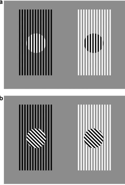
[image:2.595.68.250.70.170.2]Fig. 2. (a) Anderson and Winawer’s black and white disks. The 4 disks on the left are identical to the 4 on the right, yet those on the left appear black while those on the right appear white. (b) Anderson and Winawer’s control stimulus in which the disks have been rotated, eliminating the perception of transparency and the lightness illusion.
Fig. 3. A modification of Anderson and Winawer’s black and white disks. The rightmost disk of the four in Anderson and Winawer’s original display has been copied and pasted at two additional locations in the image. These additional targets will generally appear to be partly obscured by transparent clouds too, as long as the contrast polarity along most of the length of their boundaries is in the right direction. Continuity of the direction of the gradient associated with the clouds is generally not necessary. However, a lack of such continuity, or inconsistency with the perceived occlusion of other nearby targets can create the perception that a target is at a different depth within the clouds than other nearby targets, or that a target is slanted in depth (e.g., the target pasted on the upper right on the dark side of the display. See text for further details.).
[image:2.595.91.497.367.464.2] [image:2.595.143.439.532.681.2]one another, the geometrical and luminance constraints on perceptual transparency are very different from the case of transparent ‘overlays’.Anderson (1997) proposed that:
‘‘When two aligned contours undergo a discontinuous change in the magnitude of contrast, but preserve con-trast polarity, the lower concon-trast region is decomposed into two causal layers.’’ (page 2)
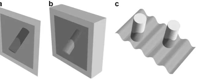
This constraint in invalid when configurations of interpenetrating objects are allowed (as when solid objects are seen as penetrating transparent clouds). For example, Fig. 4a shows a cylinder penetrating a transparent surface. Here, aligned contours (the straight edges of the cylinder) undergo a discontinuous change in the magnitude of contrast and preserve contrast polarity, but it is the higher contrast region that is decomposed into two causal layers. Further, Fig. 4b shows that decomposition into two causal layers can also occur when two aligned contours undergo a discon-tinuous change in the magnitude of contrast but reverse contrast polarity. Fig. 4c demonstrates these two con-trast relationships on opposite sides of each of the two cylinders.
A similar effect can be seen inFig. 3. Here, one of the target regions fromFig. 2a has been copied and pasted at two new locations in the image. Subject to the constraint that the contrast polarity is maintained along most of the length of the boundary, the targets will generally appear to be viewed through transparent clouds without much restriction on where they are placed. Continuity of the direction of the luminance gradient along the target boundary does not appear to be a strong constraint. How-ever, the new targets may appear to be at different depths within the clouds than the original targets, nearer and/or slanted in depth. For example, the left side of the new
tar-get pasted on the upper right on the dark side of Fig. 3 appears to be nearer and seen though less cloud material then the other nearby targets. This is because the new tar-get is very light and has high contrast on its left side, but the background is very dark in that region, and parts of two nearby targets from the original display appear to be almost completely obscured and darkened by that patch of dark cloud. Thus, the visual system infers that the left side of the new target must be closer than the obscured targets in the region of that dark cloud patch. But since the right side of the new patch is quite dark and its right edge has relatively low contrast, the new target appears slanted in depth from left to right, penetrating into the dark clouds.
The transparency percepts in Fig. 4 are somewhat less stable than in displays depicting ‘overlay’ transparency (e.g., as seen inFigs. 1a and7a). This is likely due to the fact that interpreting the luminance differences in an overlay transparency display as being due to differences in the reflec-tances of opaque surface regions violates principles of ‘non-accidentalness’. This is not the case for displays depicting penetration of transparent surfaces, such as those shown in Fig. 4. Although, non-accidentalness considerations do not preclude non-transparent interpretations of Anderson and Winawer’s displays either (as indicated above), the ten-dency not to interpret slow achromatic luminance gradients as reflectance changes (e.g., Kingdom, 2003) is likely to be operative inFig. 2a, which might explain why the gradients tend to be perceived as due to either transparent clouds (as inFig. 2a) or to shading (as in the rotated, contrast-revers-ing targets inFig. 2b), but not paint.
[image:3.595.144.466.69.198.2]similar displays problematic. I argue that the strength of Anderson and Winawer’s illusions is mainly due to the per-ception of transparency per se, combined with known light-ness mechanisms.
2. Lightness Illusions from occlusion?
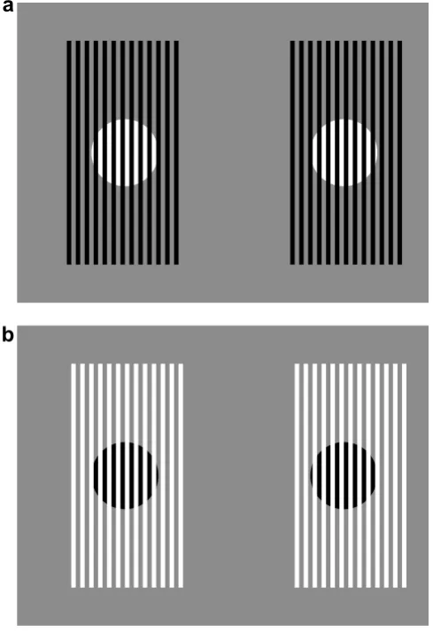
Anderson and Winawer suggested that decomposition of image luminance into multiple causal layers (e.g., perceptual transparency) is critical for the lightness illusions presented in their paper. However, I suggest that the effects seen in Anderson and Winawer’s displays may be largely based on factors that are closely related to those present in simple occlusion displays, even though occlusion does not involve layered decomposition of luminance (i.e., perceptual scis-sion). For example, the disk-shaped targets inFig. 5a are identical; they are composed of the same alternating black
and white stripes. However, on the left the black stripes of the target were extended into the grey surround, while on the right the white stripes of the target were extended. On the left a white disk is seen against a grey background with black bars in front, while on the right a black disk is seen against a grey background with white bars in front. Thus, just an in Anderson and Winawer’s displays, the target is seen as white in one case and black in the other, although both targets (the virtual disks) are identical inhomogeneous (striped) image regions. The important point is that there is no layered decomposition of image luminance here, only per-ceived occlusion. If the ‘lightness illusions’ seen in such occlusion displays are primarily based on mechanisms simi-lar to transparency mechanisms related to those involved in Anderson and Winawer’s illusions, then layered luminance decomposition may be unnecessary for the kind lightness illusion presented by Anderson and Winawer. In other words, if we ignore the non-essential additional consider-ations introduced by Anderson and Winawer’s use of ran-dom gradients (see Fig. 7), the occlusion case and the transparency case are distinguished by the presence of T-junctions in the former case and X-T-junctions in the latter. The T-junctions signalling occlusion can be viewed as the opaque limiting case as the transparent surface is made less and less transparent.
The construction ofFig. 5a is completely analogous to that of Anderson and Winawer’s displays, except that it uses only three grey-levels instead of hundreds. In Ander-son and Winawer’s displays, the ‘seed image’ was randomly generated using a spatial-frequency power spectrum of 1/f2, and its luminance range was compressed and shifted to range either between grey and white or between black and grey in the background region, while the targets were left to range between black and white. I started with a ‘seed image’ of alternating black and white stripes, and then applied exactly the same transformation to produce Fig. 5a. (A movie version is available as Supplementary information.) The target regions in Fig. 5b have been rotated relative to their original orientation, thereby elimi-nating the perception of occlusion.
[image:4.595.39.278.299.653.2]More of the surface area of the perceived targets is vis-ible in Anderson and Winawer’s displays than inFig. 5a. Only half of the target area (the virtual disk) is visible in Fig. 5a. The remainder is perceived to be occluded by the bars. Thus, it might be suggested that the lightness illusion inFig. 5a is more dependent on amodal completion of the targets behind the occluding stripes than Anderson and Winawer’s illusions. However, consider the stereoscopic version ofFig. 5a shown inFig. 6. The binocular disparity of the disks is exactly equal to the width of a single stripe. Thus, the regions of the disks inFig. 6that are occluded in the image presented to one eye are visible to the other eye. Thus, the visual system doesn’t really have to do any amo-dal completion of the targets behind the occluding bars in Fig. 6. Of course, we still perceive a white disk in the upper stereogram and a black disk in the lower one, even though both stereograms have identical target regions. Similarly, Fig. 5. (a) Lightness from occlusion. The light-colored disk on the left and
the Supplementary movie stimulus shows a sequence of frames in which the targets are identical in each frame (although they change from frame to frame). Again, a white disk is seen on the left, and a black disk is seen on the right.
3. On the relationship between Anderson and Winawer’s effects and previous work on lightness illusions and perceptual transparency
Anderson and Winawer’s effects are not fundamentally new. Similar effects can be seen in most perceptual trans-parency displays of the sort studied for at least the past 30 years (e.g., Metelli, 1974). The major difference is that the transparent layers perceived in Anderson and Wina-wer’s displays are inhomogeneous (evoked by the slow gra-dients), whereas the transparent layers perceived the displays used in most previous studies of perceptual trans-parency were homogeneous. However, the same sort of illusions can be readily obtained with perceptually homoge-neous transparency, as can be seen inFig. 7. What is new in Anderson and Winawer (2005)is primarily only the claim that such effectsarelightness illusions.
[image:5.595.46.291.70.427.2]Assuming that Anderson and Winawer’s effects are properly considered to be lightness illusions, what makes them stronger (at least according to Anderson and Wina-wer’s measurement procedure) than previous lightness illu-sions involving perceptual transparency, such as those investigated byAdelson (2000)? One possibility is that once the visual system has constructed the transparency percept, it simply has to compare the luminances of the parts of the targets perceived to be in plain view (see the simplified ver-sion of Anderson and Winawer’s displays in Fig. 7). In other words, in Anderson and Winawer’s displays the visual system is able to view parts of the two targets under Fig. 6. A stereoscopic version ofFig. 5a. A white disk is seen on the top
and a black disk on the bottom. Since the binocular disparity of the disks is equal to the width of one stripe, all parts of the disks are visible to one or the other eye, so the visual system need not rely on amodal completion of the perceived disks behind the occluding stripes to infer their complete-ness. (Fuse the images by crossing the eyes.)
[image:5.595.130.478.529.694.2]the same perceived conditions of transparency/illumina-tion, and the targets have very different physical lumi-nances there. In Anderson and Winawer’s displays the visual system could simply make a veridical luminance comparison of the darkest part of the dark target to the lightest part of the light target. (In my occlusion display the observer might simply compare the parts of the disks that are perceived as unoccluded.) However, it is very likely that factors already known to affect lightness perception are at work in Anderson and Winawer’s effect too. Thus, the perceived lightness of the darkest and lightest parts of targets (as computed by a frameworks or image statistics model) is likely to determine the relative lightness of the two disks, not their relative luminance.
Even if Anderson and Winawer’s illusions are based on layered decomposition, there would be no need for the visual system to make any but the simplest inferences about the transmittance or reflectance of the transparent surfaces. It would only need to infer that the transparent surfaces are in the scene (based on X-junctions and related gradient cues to transparency, see below), and that the targets are perceived to have the same reflectance in the regions that are seen through the transparent surfaces as in the regions that are seen in plan view. In Fig. 7, this last inference is supported by the fact that the two halves of the squares each have uniform luminance. Thus the only way that the reflectances of the squares inFig. 7could be changing is if (1) they changed coincident with the transparency bor-der, or (2) the parameters of the transparency and the reflectances of the squares are changing simultaneously and precisely canceling out each other’s effects on image luminance in the regions of overlap (since the image lumi-nances are uniform in the regions of overlap). Both of these possibilities are unlikely coincidences that are probably not considered by the visual system. These ‘non-accidentalness’ arguments can be partially extended to Anderson and Winawer’s gradient displays as well.1 However, the main reason why the targets in Anderson and Winawer’s dis-plays are likely to be seen as uniform is because of the ten-dency not to interpret slow luminance gradients as reflectance changes, since there are no abrupt gradients inside Anderson and Winawer’s targets.
The visual system could not use either of the above strat-egies in Adelson’s displays (e.g.,Fig. 1). If perceptual trans-parency and layered decomposition of image luminance plays a significant role in Adelson’s effects, then the visual system would have to try todiscountthe effects of the two
perceived transparent surfaces on the image luminances of the target regions in order to infer what the two targets would look like under the same viewing conditions, since the targets are not perceived to be under the same viewing conditions in any regions of the image. This would clearly be a much more difficult and error-prone task, requiring a relatively quantitative computation of the effects of the transparent surfaces on the image luminances (e.g., com-puting the reflectance and transmittance of both transpar-ent surfaces). In Anderson and Winawer’s displays no discounting computation would be necessary once the visual system had simply qualitatively inferred that the transparency is present in the scene and that the disks are uniform. Thus, the apparently greater strength of Ander-son and Winawer’s illusions might simply be due to observ-ers’ ability to perceive which image regions are relatively ‘unobscured’ by the clouds, followed by a lightness compu-tation of the kind that previous researchers have suggested. Anderson and Winawer’s displays contain features that would be likely to evoke strong lightness illusions accord-ing to models based on frameworks (Gilchrist et al., 1999) or image statistics (Adelson, 2000), since they contain complex backgrounds containing a large number of differ-ent grey-levels.
Adelson’s displays give rise to percepts of transparency and produce lightness illusions that are much stronger than simple simultaneous contrast. This is consistent with the possibility that these effects arise partly because the visual system is trying to discount the influence of perceived transparency/illumination differences to recover back-ground surface reflectance. However, many (but not all) alterations to Adelson’s displays that disrupt or even abol-ish the transparency percepts in his displays do not greatly weaken the lightness illusions (Albert & Finkel, 1996; Bres-san, 2006; seeFig. 8). In contrast, Anderson and Winawer’s lightness illusions seem to be greatly weakened by manipu-lations that disrupt the conscious perception of
transpar-1
In Anderson and Winawer’s displays, the orientation of the gradient is continuous across the boundaries the targets. This image structure would be accidental if there were a slow change in the reflectance of the target in the annular region near its border. Although this reasoning does not preclude a slow change in the reflectance of the target in its interior, it makes it unlikely if the target’s reflectance changes and the position of its boundary are assumed to be independent. However, as indicated above, continuity of the orientation of the gradient across the boundaries the targets is generally not necessary for the transparency and lightness effects seen in Anderson and Winawer’s gradient displays.
a
b
[image:6.595.328.524.530.690.2]ency (e.g.,Fig. 2b). Thus, transparency mechanisms might combine with the other lightness factors that operate in Adelson’s displays and other lightness illusions (e.g., artic-ulation-like effects due to the gradients) to produce the very strong effects seen in Anderson and Winawer’s displays. Moreover, in contrast to Adelson’s displays, Anderson and Winawer’s target boundaries (and those in Fig. 7a) contain the very image structure that evokes the perception of transparency, so their lightness and transparency effects might be inseparable.
Fig. 9a is a variant ofFig. 5a in which transparent rather than opaque strips can be seen in front of the disks. How-ever, it is also possible to see the disks as transparent or as holes in transparent surrounds. The lack of a similar ambi-guity inFig. 2a might be due to the tendency not to inter-pret slow gradients as reflectance changes. Thus, inFig. 2a the abrupt edges surrounding the targets must be seen as reflectance edges and the random (mostly low
spatial-fre-quency) gradients as defining the transparent overlay, rather than the reverse.
In any case the disk on the left inFig. 9a consistently looks much lighter than the one on the right, and the illusion is greatly reduced when the disks are rotated, as in Fig. 9b. However, in contrast toFig. 5b the disks inFig. 9b maintain consistent contrast polarity all the way around their bound-aries. As can be seen, the lightness illusion inFig. 9b is some-what stronger than the one inFig. 5b, but at the same time the lightness illusion inFig. 9a is much stronger than the one inFig. 9b. Thus, consistent contrast polarity is not suffi-cient for the strength of the illusion seen inFig. 9a, suggesting that the same may be true forFigs. 5a and2a.
4. Outline of an algorithm for computing lightness
It might be suggested that Anderson and Winawer’s effects could be predicted by edge-integration algorithms.
[image:7.595.142.462.293.712.2]Edge-integration algorithms for recovering lightness com-pute the relative lightness between two image patches by summing the abrupt luminance changes along any path connecting the two patches, disregarding any gradual lumi-nance changes. The assumption is that abrupt lumilumi-nance edges represent reflectance changes between adjacent image regions and that the ratio of the two luminances is the same as the ratio of their reflectances (if the algorithm is to pro-duce veridical results), while gradual luminance changes represent illumination changes and should be ignored when computing relative lightness. Anderson and Winawer’s dis-plays contain both abrupt and gradual luminance changes, however, the gradual luminance changes in their displays are usually interpreted as changes in the density (transpar-ency) of clouds in the foreground, rather than as changes in illumination or shading. In the case of transparency, the assumption that the ratio of the two luminances across an abrupt luminance change is the same as the ratio of the reflectances of the background surfaces is not valid, since the transparent layer can have non-zero reflectance and thereby reduce image contrast. Thus it seems unlikely that previously proposed edge-integration algorithms could explain Anderson and Winawer’s effects. Moreover, it has been has argued that the visual system could not recover lightness using edge-integration algorithms even when only illumination changes are considered (e.g., Adelson, 1993, 2000; Gilchrist et al., 1999). One problem is that illumina-tion edges can be abrupt in 3D scenes, and therefore should not be included in the sum of abrupt luminance changes computed during edge integration.
However, since the targets in Anderson and Winawer’s displays do not contain any abrupt edges there is no need for the visual system to quantitatively integrate over paths that cross multiple reflectance edges and (somehow) dis-count the perceived transparency. The system simply needs torefrainfrom changing its lightness estimate as the image luminance slowly varies within the target boundaries. In other words, since slow luminance gradients tend not to be interpreted as reflectance changes, and there are no abrupt edgesinside the targets, the targets can be inferred to have uniform reflectance. This allows the visual system to ‘discount’ the effects of the transparency without the need to quantitatively compute any of the properties of the transparent clouds (e.g., its transmittance or reflectance).
Thus, I suggest that Anderson and Winawer’s effects are consistent with the view that the visual system does not form global reflectance and illumination/transparency maps to compute lightness. The representations used to make lightness judgments would be constructed using sim-ple rules such as (1) the highest contrast part of an edge is perceived to be in ‘plain view’ (Anderson, 2003), and (2) slow luminance gradients are due to changes in illumina-tion/transparency rather than to changes in background reflectance.
Specifically, I propose the following algorithm for com-puting lightness:
1. Compute transparency in the image, e.g., look for polar-ity preserving contours at X-junctions and their ana-logues for slow gradients (as in Anderson & Winawer, 2005), and determine which regions are in ‘plain view/ normal illumination’.
2. Run a frameworks (Gilchrist et al., 1999) or image sta-tistics algorithm (Adelson, 2000), using allimage lumi-nances, to find the relative lightness’ of only the regions perceived to be in plain view, anchoring the highest luminance to white.
3. Propagate lightness values from the plain-view regions across all gradients (slow or abrupt) that are perceived (due to generalized X-junction structure) to be due to illumination or transparency, but do not propagate lightness signals across perceived reflectance edges. Since slow luminance gradients tend not to be interpreted as reflectance changes, the algorithm automatically propa-gates across slow gradients without the need for further edge classification computations.
4. Run a standard 2D frameworks (Gilchrist et al., 1999) or image statistics (Adelson, 2000) algorithm on the complete image.
5. Compute the final lightness by taking a weighted combi-nation of the outputs of steps 3 and 4, with the weights determined by the salience of the scission percept.
Note that this algorithm does not construct a quantita-tive layered decomposition of the image in the sense that it does not contain exact values of foreground transmittance or background reflectance at all points in the image (other than the background reflectance values that can be obtained via the lightness propagation heuristic described in step 3 above). I suggest that we only use layered repre-sentations to infer which image regions are background regions seen in ‘plain view’. Beyond that, we simply use a frameworks or a image statistics algorithm (step 2 above) and then propagate the computed lightness values across perceived illumination/transparency gradients (step 3).
In my Fig. 7a the transparency percept is perhaps less salient than in Anderson and Winawer’s displays (e.g., Fig. 2), so the lightness effect might be weaker (in addition to the fact that the physical luminances of the target regions seen in plain view are more similar in Fig. 7a). I suggest that inFig. 7a one can use certain viewing strate-gies to switch between seeing transparency and not (in varying degrees), and that when transparency is not seen, or is weak, the ‘weight’ used in step 5 for the output of the computation in step 3 is correspondingly smaller.
effects are, in all relevant respects, identical to those described by researchers in perceptual transparency going back at least toMetelli (1974), as illustrated inFig. 7. This is in contrast to the lightness illusions (also involving per-ceptual transparency) previously described by Adelson (1993, 2000)and others.
Appendix A. Supplementary data
Supplementary data associated with this article can be found, in the online version, at doi:10.1016/j.visres. 2007.06.004.
References
Adelson, E. H. (1993). Perceptual organization and the judgement of brightness.Science, 262, 2042–2044.
Adelson, E. H. (2000). Lightness perception and lightness illusions. In M. Gazzaniga (Ed.), The new cognitive neuroscience (2nd ed., pp. 339–351). Cambridge, MA: MIT Press.
Albert, M. K., & Finkel, L. H. (1996). Brightness illusions in simple geometrical figures.Opthalmology and Visual Science Supplement, 7(3), 3001. Anderson, B. L. (1997). A theory of illusory lightness and transparency in
monocular and binocular images: The role of contour junctions. Perception, 26, 419–453.
Anderson, B. L. (2003). The role of occlusion in the perception of depth, lightness, and opacity.Psychological Review, 110, 785–801.
Anderson, B., & Winawer, J. (2005). Image segmentation and lightness perception.Nature, 434, 79–83.
Bressan, P. (2006). The place of white in a world of grays: A double-anchoring theory of lightness perception. Psychological Review, 15, 526–553.
Gilchrist, A. L., Kossyfidis, C., Bonato, F., Agostini, T., Cataliotti, J., Li, X. J., Spehar, B., Annan, V., & Economou, E. (1999). An anchoring theory of lightness perception.Psychological Review, 106, 795–834. Kingdom, F. A. A. (2003). Colour brings relief to human vision.Nature
Neuroscience, 6, 641–644.
Logvinenko, A. D., & Ross, D. A. (2005). Adelson’s tile and snake illusions: A Helmholtzian type of simultaneous lightness contrast. Spatial Vision, 18, 25–72.
Lotto, R. B., & Purves, D. (1999). The effects of color on brightness. Nature Neuroscience, 2, 1010–1014.
Metelli, F. (1974). The perception of transparency. Scientific American, 230, 90–98.
Purves, D., Williams, S. M., Nundy, S., & Lotto, R. B. (2004). Perceiving the intensity of light.Psychological Review, 111, 142–158.
Williams, S. M., McCoy, A. N., & Purves, D. (1998a). The influence of depicted illumination on brightness. Proceedings of the National Academy of Sciences of the United States of America, 95(22), 13296–13300.