City, University of London Institutional Repository
Citation
:
Atkin, C.J. & Backer Dirks, T. (2015). Systems driven HLFC design. Paper
presented at the 50th 3AF International Conference on Applied Aerodynamics, 30 Mar - 01
Apr 2015, Toulouse, France.
This is the accepted version of the paper.
This version of the publication may differ from the final published
version.
Permanent repository link:
http://openaccess.city.ac.uk/14093/
Link to published version
:
Copyright and reuse:
City Research Online aims to make research
outputs of City, University of London available to a wider audience.
Copyright and Moral Rights remain with the author(s) and/or copyright
holders. URLs from City Research Online may be freely distributed and
linked to.
50h 3AF International Conference
on Applied Aerodynamics
29-30 March – 01 April 2015, Toulouse - France
FP63-2015-BackerDirks
SYSTEMS DRIVEN HLFC DESIGN
50th 3AF INTERNATIONAL CONFERENCE ON APPLIED AERODYNAMICS
Toulouse, France, 29-30 March - 01 April 2015 Tobias Backer Dirks (1), Chris Atkin (2)
(1) City University, 10 Northampton Square, London, EC1V 0HB, Email: [email protected]
(2) City University, 10 Northampton Square, London, EC1V 0HB, Email: [email protected]
ABSTRACT
The paper presents an aerodynamic study carried out in parallel with the EU AFLoNext project to assess the issues involved in combining hybrid laminar flow control (HLFC) technology for drag reduction with wing ice protection systems (WIPS). The paper describes the selection of appropriate test cases in the literature which are representative of wings designed for HLFC system and the progression from an initial baseline HLFC chamber layout to layouts driven by practical constraints such as WIPS requirements and aircraft structure. The resulting HLFC system is a compromise between all concerned systems. Conclusions are drawn about design driven not purely by performance but by the ability to physically implement the system on a commercial aircraft.
1. INTRODUCTION
Laminar flow technology aims to maintain laminar boundary layer flow over lifting surfaces, engine nacelles and the vertical tail in order to reduce drag. At the high Reynolds numbers typical of transport aircraft this usually requires careful aerodynamic design to promote favourable pressure gradients to delay the growth of streamwise instabilities which lead to laminar-turbulent transition. Swept wings are also susceptible to crossflow instabilities which are excited by the favourable pressure gradients needed to suppress streamwise instabilities, so the aerodynamic design is augmented by the use of surface suction to suppress these crossflow instabilities. Such an approach which employs both passive control, by means of shape, as well as active control, by means of boundary layer suction, is known as hybrid laminar flow control (HLFC).
HLFC has been the subject of numerous studies, notable European efforts including the collaborative ELFIN and ELFIN 2, HYLDA, HYLTEC, ALTTA and TELFONA programmes, as well as flight tests carried out on an A320 fin [1]. The most recent HLFC studies are being carried out with the AFLoNext [2] project (which also looks at a number of other technologies for flow control, as well as loads control). One of the activities within AFLoNext is the advancement of technologies required to implement HLFC on a wing by the design and construction of a ground-based demonstrator (GBD). The role of City University London within this activity is to support the aerodynamic design of the GBD, principally in respect of specifying the required suction rates for an in-service HLFC system appropriately sized for the GBD. While HLFC systems have been incorporated and tested on non-lifting surfaces in a number of previous projects, the wing presents additional challenges in terms of coexistence with other critical systems such as high-lift, ice protection and bird-strike protection. This necessitated a ‘step-up’ of the aerodynamic analysis to be able to observe layout constraints – or indeed to facilitate layout trade studies – with no significant penalty either for the design process or for the aerodynamic performance of the final design solution.
The methodology applied by City is almost unchanged from the HLFDes tool developed by the
2nd
re-compression following the initial acceleration of the flow around the leading edge of the wing), while the AFLoNext study followed the more traditional design philosophy for laminar flow wings, namely to ensure a favourable rooftop pressure gradient to delay the development of streamwise instabilities (TS waves).
For the avoidance of commercial sensitivities, the activities reported here represent a parallel study, undertaken outside the AFLoNext project, using the RAE 2822 [4] and 5243 aerofoil sections which are available in the open literature. (The RAE 5243 section is more commonly referenced as the DRA 2303 model.) These sections provided the HLFDes analysis tool with very similar challenges to those encountered during the AFLoNext work.
Likewise the purpose of the paper is not to present aerodynamic results indicative of those in the AFLoNext project but to illustrate the interaction between the aerodynamic analysis and realistic system and manufacturing constraints found on a real aircraft wing. In the process some assumptions of the HLFDes methodology are thrown into sharp relief: in one sense the purpose of the paper is to challenge the view that the aerodynamics of HLFC are mature, at least within the context of sizing and integrating an HLFC system into a wing leading edge.
2. COHABITING SYSTEMS AND SYSTEM
CRITICALITY
The leading edge cavity on a commercial aircraft is a highly confined and contested space. The implementation of an HLFC system requires it to coexist with other critical systems such as leading edge devices and anti-icing systems.
Super-cooled water droplets that exist at ambient temperatures below freezing, where commercial aircraft operate, can cause aircraft icing. When these droplets impinge on the leading edge of the aircraft and come in contact with any small dust or dirt particles these will act as ice nuclei and result in rapid ice formation. The resulting ice will tend to act as a catalyst for further ice formation.
This build-up of ice can have dangerous side effects. For example, a degradation in aerodynamic performance due to increases in weight, lift and drag, the inability to deploy leading edge devices or even loss of control surface authority. In order to avoid this wing ice protection systems (WIPS) are used. The most common forms of these are:
• Electro-thermal WIPS - These use insulated
conductive foils which generate heat when a current is applied.
• Bleed air systems - Which use hot air which
has been ducted from the jet engines.
• Passive systems - These make use of
hydrophobic materials and paints which are able to repel water and have a self-cleaning effect that helps reduce ice build-up.
Certification requires commercial aircraft to have WIPS installed, and be effective, both in continuous maximum and intermittent icing conditions as described in Appendix C of ACJ 25-1419. Any HLFC system must be built around WIPS without impeding its operation of effectiveness.
Equally, leading edge devices allow the aircraft to generate increased lift at lower velocities by increasing effective camber. Modern variants, such as fully-retractable folding bull-nose Krueger flaps, require a large amount of space within the leading edge cavity to be stowed away. Add to this the hydraulic systems and pumps required to operate both these systems and space is at a premium. The location of the front spar, which acts as a hard limit due to the location of the fuel tanks in the next section further restricts space.
While HLFC systems are desirable in terms of performance gains and fuel saving they are not critical to the successful completion of a given mission. Therefore the challenge in implementing an HLFC system on a lift generating surface rather than a vertical fin concerns itself with not only performance but the ability to cohabit the leading edge space without affecting the performance of other, more critical systems.
3. TEST CASE SELECTION
Traditionally both NLF and HLFC aerofoils exhibit favourable rooftop pressure gradients which reduce Tollmien-Schlichting (TS) instability growth in the mid-chord region, although the addition of sweep makes these pressure distributions susceptible to Crossflow (CF) instability growth, both at the leading edge and further downstream. The optimum rooftop pressure distribution for HLFC – from the perspective of minimising the suction requirement – is one where the suction required to control TS modes, and that needed to control CF modes, is comparable. However the quantification of minimum suction requirement is, in the opinion of the authors, still a moot point despite being highlighted many
years ago by the 2nd
For a given shock position and strength, there is an inverse relationship between the rooftop pressure gradient and that at the leading edge, where the flow accelerates most rapidly, and where strong suction is essential to control CF growth near the leading edge. With these characteristics in mind, two aerofoil sections were considered for this study, namely RAE5243 and RAE2822 [4]. In order to be representative of a transonic transport aircraft, the
aerofoils were analysed at a CL of 0.5 and swept
back to accommodate a cruise Mach number of 0.8 or greater. Both sweep and taper were modelled using the approach described in ref. [6].
Figure 1 - RAE2822 and RAE5243 pressure distributions.
Fig. 1 illustrates the type of pressure distributions which can be obtained from these aerofoils. The 5243 section has a pronounced favourable rooftop pressure gradient but, having a smaller leading edge radius, a more gradual initial acceleration than RAE 2822. The 2822 section has a less favourable rooftop pressure gradient but, importantly, this rooftop follows a short ‘lip’ of adverse pressure gradient at the start of the rooftop. The initial acceleration of the flow to transonic speeds also occurs over a much shorter distance than for the 5243 section. Increasing free stream Mach number and reducing trailing edge sweep angle (thereby reducing taper ratio) both result in a stronger shock wave at a given value of lift coefficient, which limits the applicability of the RAE5243 section for this work. Mitigating the shock strength by increasing leading edge sweep resulted in excessive leading edge suction requirements (not shown here). The RAE 2822 section, however, proved very versatile and it can be seen from Fig.1 that representative Mach number and sweep angles could be achieved using this section.
The aforementioned suction peak/lip in the RAE2822 pressure distribution proved to be a key
characteristic in the viability of HLFC for this aerofoil as this feature seems to provide natural damping of
crossflow instability between s/c 0.05 and 0.1.
Consequently, RAE2822 was chosen to complete the study. The aerofoil was transformed to a swept-tapered wing section (leading edge sweep 35°,
trailing edge 22°) operating at a 3D CL of 0.55,
cruise speed of Mach 0.85 and chord Reynolds number of 28 million (representing a wing of chord 3.5m operating at 32 kft ISA).
4. METHODOLOGY
The QinetiQ HLFC analysis tools [3] are tried-and-tested for this sort of work. Transonic pressure distributions were calculated using the Garabedian and Korn (VGK) full-potential method [7] coupled with the Airbus boundary layer analysis code, Callisto. Pressure distributions were then fed into the BL2D finite-difference laminar boundary layer solver, and the resulting boundary layer profiles
were analysed using the CoDS eN method. The
BL2D and CoDS methods are directly coupled to the Callisto code [8] , so the process is seamless and, aft of the predicted transition location, the analysis concludes with a turbulent boundary layer calculation using Green’s integral Lag-Entrainment approach [9].
For the present work, TS and crossflow
amplification rates were calculated using
incompressible, 3D, parallel-flow, spatial stability theory and integrated following the constant-spanwise-wavenumber strategy, with travelling crossflow modes excluded from consideration. Transition positions were determined using a
two-N-factor approach with NCF = 7.0 and NTS = 9.0.
Both the application of suction to the laminar boundary layer and the ensuing change in transition position will alter the thickness of the boundary layer around the wing section, and therefore the pressure distribution. However the coupling between these modest changes to the mean flow and the resultant alterations to the HLFC suction requirement was very weak, and the investigation was carried out without repeating the viscous G&K analysis each time the suction parameters were altered. However an expected extent of laminar flow was assumed by computing the baseline mean flow with transition locations of 30% chord on the upper surface at 5% chord on the lower surface.
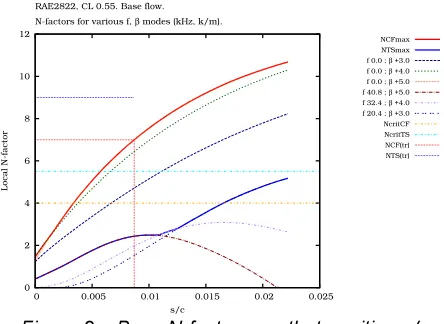
Fig. 2 shows the baseline N-factor growth for the transformed (swept and tapered) RAE2822 section
at the given conditions. Transition occurs at x/c
described above, the figure also includes lines at N-factor ‘control’ values of 4.0 for crossflow and 5.5 for TS modes: these will be explained in subsequent sections.
Figure 2 – Base N-factor growth, transition x/c 0.009.
In addition to a seamless laminar/transition capability, Callisto also incorporates a user interface for specifying HLFC suction chambers: chamber positions, plenum pressures and porous skin characteristics can all be defined by the user. The quadratic pressure loss model required to convert plenum chamber pressures (and external, inviscid flow pressures) into transpiration rates required for the laminar boundary layer analysis is also now incorporated into Callisto.
This embedding in Callisto of the suction chamber
modelling (along with the boundary layer and eN
analysis) means that the tool set used for the present work has evolved considerably since the previous HYLTEC study of realistic, discrete-chamber suction system concepts [3]. In that work the suction chamber modelling was carried out by a special tool, HLFDes, which included a facility to iterate on chamber pressures to satisfy a local maximum N-factor constraint. For the present work HLFDes has been stripped of much of its functionality and is now reduced to a crude optimisation tool whose object function is a set of target N-factors. The rationale behind this method development was to incorporate as much of the core suction system modelling within Callisto, to enable it to be used for HLFC optimisation with commercial tools such as ModelCenter, and with more relevant cost functions (such as transition position, viscous drag or – more completely –
overall HLFC performance, incorporating
aerodynamic drag reduction, suction system power draw, impact on engine sfc and system weight penalties). This has been successfully achieved within the AFLoNext project; while the reduced
HLFDes tool has still delivered a useful contribution in terms of assessing the suitability of a particular chamber layout from an aerodynamic perspective, allowing many poor layouts to be eliminated from consideration early in the design process.
To re-cap on the methodology used for the present work, HLFDes is used to run Callisto iteratively (for fixed inviscid flow conditions) to help optimise plenum chamber pressures for a swept-tapered HLFC wing of constrained geometry and chamber layout. HLFDes requires user-defined plenum chamber locations and sizes which can then be adjusted on the basis of the ‘best’ chamber pressures (and mass flow rates) returned by the HLFDes analysis. As with other low order methods the benefits lie with the speed of calculation. This allows for rapid design iteration, proving itself extremely useful during design workshops with other project partners in which new designs, or affecting constraints, can be implemented within a matter of minutes allowing for further discussion.
[image:5.595.314.534.491.666.2]Using the HLFC design tool, and following the N-factor control philosophy described in ref. [3], a preliminary suction chamber layout was devised. Figures 3 through 7 depict the process: an initial chamber layout, leading to a set of chamber pressures satisfying (though not invariably) a target N-factor distribution, followed by user revision of the chamber layout (including removal of suction zones altogether). The target N-factor distribution was simply a pair of constraints on the development of crossflow (N < 4.0) and TS (N < 5.5) N-factors over the first 25% of wing chord.
Figure 3 – Preliminary suction plenum chamber layout.
Initially chambers were placed throughout the upper surface from attachment line to front spar location as seen in Fig. 3 in order to establish the most crucial suction zones. The resultant amplification rates in Fig. 4 and chamber pressures in Fig. 5 were
0 2 4 6 8 10 12
0 0.005 0.01 0.015 0.02 0.025
Local N-factor
s/c RAE2822, CL 0.55. Base flow. N-factors for various f, β modes (kHz, k/m).
NCFmax NTSmax f 0.0 ; β +3.0 f 0.0 ; β +4.0 f 0.0 ; β +5.0 f 40.8 ; β +5.0 f 32.4 ; β +4.0 f 20.4 ; β +3.0 NcritCF NcritTS NCF(tr) NTS(tr)
L U
0.00 0.05 0.10 0.15 0.20 0.25
z/c
x/c RAE2822, CL 0.55, ID 32k. Chamber arrangement cq00. Final.
analysed in order to minimize the size and location of chamber placement while remaining within control limits.
[image:6.595.313.534.309.467.2]Figure 4 – Preliminary N-factor growth, transition x/c 0.409.
Figure 5 – Preliminary plenum chamber pressures.
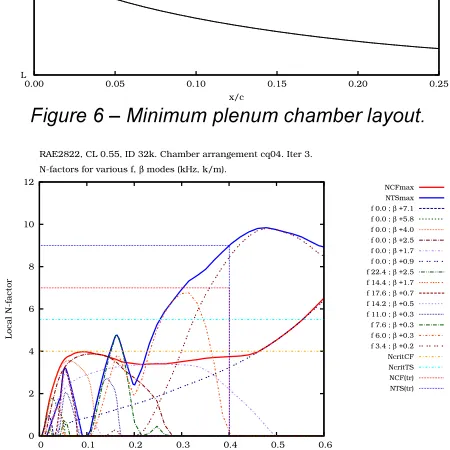
After various iterations the chamber layout converged on a requirement for 3 suction zones, with a double-plenum chamber in the nose providing independent control of the attachment line momentum thickness (a region of the flow where N-factors are not the critical metric for laminarity). The 3 zones are shown in Fig. 6 are leading edge zone, an intermediate zone and a final aft zone.
The attachment line/leading edge zone, in this case
between s/c -0.005 and 0.01, is arguably the most
critical zone as it controls initial CF amplification. The following, intermediate suction zone, here from
s/c -0.05 and 0.1, acts to damp CF growth
immediately downstream of the pressure ‘lip’ characteristic at the start of the rooftop. In the process it completely damps TS modes suggesting that, in this region, a longer ‘lip’ of adverse pressure gradient in the external flow development would reduce the suction requirement for CF control without increasing the risk of TS growth.
Finally, the aft chamber is positioned as far back as is allowed by the position of the front spar and controls the amplification of the TS waves which ultimately lead to transition. Thus the effect of this last chamber, and the amount of suction applied, largely dictates transition location. This allows for some compromise between suction mass flow rates and desired transition location. Exploration of this trade-off is not one of the capabilities of the HLFDes tool, so – once a compliant chamber layout and set of plenum pressures has been established – further refinement of the chamber pressures is simply
achieved by manual intervention. This is
demonstrated in the results presented in Figures 7 & 8 where plenum pressures were adjusted, at the
expense of transition x/c, in order to impose a
[image:6.595.60.280.323.464.2]uniform plenum pressure on all the chambers. This uniformity would simplify the design of supporting systems.
Figure 6 – Minimum plenum chamber layout.
Figure 7 – Minimum configuration N-factor growth,
transition x/c 0.401.
Once the critical suction zones have been settled upon, the integration with other systems can be addressed. Dialogue with WIPS system specialists [10] during the AFLoNext project revealed a set of
0 2 4 6 8 10 12
0 0.1 0.2 0.3 0.4 0.5 0.6
Local N-factor
s/c
RAE2822, CL 0.55, ID 32k. Chamber arrangement cq00. Iter 10. N-factors for various f, β modes (kHz, k/m).
NCFmax NTSmax f 0.0 ; β +6.5 f 0.0 ; β +3.7 f 0.0 ; β +2.6 f 0.0 ; β +1.8 f 0.0 ; β +1.1 f 17.4 ; β +1.9 f 20.5 ; β +1.0 f 15.7 ; β +0.5 f 11.6 ; β +0.3 f 9.8 ; β +0.3 f 8.3 ; β +0.3 f 7.8 ; β +0.2 f 3.4 ; β +0.2 NcritCF NcritTS NCF(tr) NTS(tr) -1.50 -1.00 -0.50 0.00 0.50 1.00
0.00 0.05 0.10 0.15 0.20 0.25
Cp
s/c
RAE2822, CL 0.55, ID 32k. Chamber arrangement cq00. Final. Chamber and external pressures; oversuction limits.
Mass flux 6.43 g/s/sq.m. Pcham Plim Pwing Pinf L U
0.00 0.05 0.10 0.15 0.20 0.25
z/c
x/c RAE2822, CL 0.55, ID 32k. Chamber arrangement cq04. Final.
Wing surface Chambers 0 2 4 6 8 10 12
0 0.1 0.2 0.3 0.4 0.5 0.6
Local N-factor
s/c
RAE2822, CL 0.55, ID 32k. Chamber arrangement cq04. Iter 3. N-factors for various f, β modes (kHz, k/m).
[image:6.595.311.536.408.633.2]constraints for the location and implementation of both the WIPS and HLFC systems.
Figure 8 – Minimum configuration plenum chamber pressures.
The first challenge was that the leading edge region was critical for both HLFC and WIPS, but necessitating a dual-role for the nose chamber(s) and parallel ducting arrangements for HLFC suction and WIPS engine bleed air. As ice formation generally only occurs in clouds, so mainly during take-off and landing, this would not be a major performance sacrifice. If the WIPS system were needed during cruise then this would result in temporary loss of laminarity. The engineering of the nose chambers can be simplified by noting that, for the present study, the attachment line momentum thickness is not a ‘sizing’ metric, allowing the nose chambers to be merged together.
For the RAE 2822 derivative used for the present study, there is a region of wing skin immediately downstream of the nose and of about 4% chord in extent which can be used entirely for WIPS without hindering the controllability of crossflow instabilities. This is not the case for pressure distributions of the RAE 5243 type. This is because, for the RAE 2822, the initial acceleration of the external flowfield is contained within reasonable bounds and is terminated by a short region of adverse pressure gradient. So it would appear that this characteristic of the RAE2822 means that crossflow instability control can be contained in short zones, allowing other aircraft systems to be fitted around the HLFC infrastructure. This is an important consideration for the practical implementation of HLFC, since concepts like dual-purpose chambers may be realisable but are certainly not optimal.
The region at the start of the external pressure rooftop was again deemed equally important for both WIPS and HLFC but in this region the HLFC requirement was less constrained spatially and it
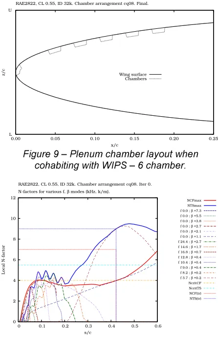
was found that sufficient control could be achieved by splitting the single suction region into two zones of reduced extent, with a gap for WIPS in between. The same approach appeared to work for the aft suction region, where moving suction forward towards the start of the rooftop appeared to be as effective in limiting the overall N-factors developed by the end of the suction region. The result was a coming together of the crossflow and TS control regions into a single mixed control zone of alternating HLFC and WIPS, such as is presented in Figure 9. The resulting N-factor distribution, Figure 10, satisfies the required constraints, but those familiar with the limitations of the theory
behind the eN
method may be sceptical that the alternating decay and re-growth of the TS instabilities would be correctly predicted, and that this sort of design solution would need some experimental validation.
[image:7.595.60.280.113.264.2]Figure 9 – Plenum chamber layout when cohabiting with WIPS – 6 chamber.
Figure 10 – N-factor growth with WIPS cohabitation, 6 chamber - transition x/c 0.422.
As shown in Figure 11, it was possible to maintain a constant plenum pressure throughout the chambers in order to simplify the implementation. Interestingly, the aerodynamic prediction methodology did not
-1.50 -1.00 -0.50 0.00 0.50 1.00
0.00 0.05 0.10 0.15 0.20 0.25
Cp
s/c
RAE2822, CL 0.55, ID 32k. Chamber arrangement cq04. Final. Chamber and external pressures; oversuction limits.
Mass flux 5.66 g/s/sq.m. Pcham
Plim Pwing Pinf
L U
0.00 0.05 0.10 0.15 0.20 0.25
z/c
x/c RAE2822, CL 0.55, ID 32k. Chamber arrangement cq08. Final.
Wing surface Chambers
0 2 4 6 8 10 12
0 0.1 0.2 0.3 0.4 0.5 0.6
Local N-factor
s/c
RAE2822, CL 0.55, ID 32k. Chamber arrangement cq08. Iter 0. N-factors for various f, β modes (kHz, k/m).
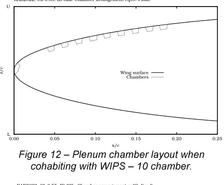
[image:7.595.312.535.308.653.2]indicate a penalty in reducing the extent of each HLFC zone while increasing the overall number of zones, Figures 12, 13 and 14.
[image:8.595.313.536.76.234.2]Figure 11 – Plenum chamber pressures with WIPS cohabitation – 6 chamber.
Figure 12 – Plenum chamber layout when cohabiting with WIPS – 10 chamber.
[image:8.595.58.280.122.278.2]Figure 13 - N-factor growth with WIPS cohabitation, 10 chamber - transition x/c 0.420.
Figure 14 – Plenum chamber pressures with WIPS cohabitation – 10 chamber.
5. CONCLUSIONS
Methodology developed during the HYLTEC project to develop HLFC chamber layouts for retrofit to the A310 aircraft has been successfully applied to a more traditional laminar flow pressure distribution concept with a largely favourable rooftop pressure gradient. However the specific toolset has evolved through the use of the Airbus Callisto boundary layer method, which now incorporates in one platform the laminar boundary layer, transition
prediction and plenum chamber modelling
previously distributed across three different methods.
Perhaps surprisingly, the swept and tapered RAE2822 aerofoil section proved considerably more amenable to HLFC than the RAE 5243 (DRA 2303) section, owing to a more compact initial acceleration around the nose and to a short region of adverse pressure gradient separating the initial flow acceleration from the favourable pressure gradient rooftop region.
Work under the AFLoNext project has
demonstrated that there are regions on the wing where HLFC and ice protection systems must share access to the wing skin; however, further away from the leading edge, the two systems can alternate if
the results of classical eN
stability analysis are to be trusted. The true effectiveness of such suction chamber configurations requires further validation.
6. AKNOWLEDGMENTS
The authors would like to acknowledge the financial support received from Airbus Group Innovations
and from the EC 7th Framework Programme under
grant agreement no. 604013.
-1.50 -1.00 -0.50 0.00 0.50 1.00
0.00 0.05 0.10 0.15 0.20 0.25
Cp
s/c
RAE2822, CL 0.55, ID 32k. Chamber arrangement cq08. Final. Chamber and external pressures; oversuction limits.
Mass flux 4.98 g/s/sq.m. Pcham
Plim Pwing Pinf
L U
0.00 0.05 0.10 0.15 0.20 0.25
z/c
x/c RAE2822, CL 0.55, ID 32k. Chamber arrangement cq09. Final.
Wing surface Chambers
0 2 4 6 8 10 12
0 0.1 0.2 0.3 0.4 0.5 0.6
Local N-factor
s/c
RAE2822, CL 0.55, ID 32k. Chamber arrangement cq09. Iter 0. N-factors for various f, β modes (kHz, k/m).
NCFmax NTSmax f 0.0 ; β +6.5 f 0.0 ; β +4.8 f 0.0 ; β +3.0 f 0.0 ; β +2.3 f 0.0 ; β +1.7 f 0.0 ; β +0.8 f 14.6 ; β +1.7 f 16.0 ; β +0.6 f 12.8 ; β +0.4 f 10.8 ; β +0.4 f 9.6 ; β +0.3 f 8.4 ; β +0.3 f 7.8 ; β +0.3 f 2.8 ; β +0.2 NcritCF NcritTS NCF(tr) NTS(tr)
-1.50 -1.00 -0.50 0.00 0.50 1.00
0.00 0.05 0.10 0.15 0.20 0.25
Cp
s/c
RAE2822, CL 0.55, ID 32k. Chamber arrangement cq09. Final. Chamber and external pressures; oversuction limits.
Mass flux 4.91 g/s/sq.m. Pcham
[image:8.595.59.282.320.504.2]7. REFERENCES
[1] R. Henke (1999). “A320 HLF Fin flight tests completed.” Air & Space Europe, vol. 1 iss. 2, pp. 76-79, ISSN 1290-0958.
[2] M. Fisher (2012). “AFLoNext: Active Flow - Loads & Noise control on next generation wing.” Seventh Framework Programme of the European Community, Grant Agreement ACP3-GA-2013-604013.
[3] C. J. Atkin (2000). “New Aerodynamic Approach to Suction System Design.” DragNet European Drag Reduction Conference, Potsdam.
[4] P. H. Cook, M. A. MacDonald and M. C. P. Firmin (1979). “Aerofoil RAE2822 – Pressure Distributions and Boundary Layer and Wake Measurements.” AGARD AR 138, App. A6.
[5] C. J. Atkin (2008). "Laminar Flow Control: Leap or Creep?" AIAA 38th Fluid Dynamics Conference and Exhibit, Seattle, WA.
[6] R. C. Lock (1962). “An equivalence law relating three- and two-dimensional pressure distributions..” NPL Aero Report no. 1028.
[7] P. Garabedian and D. Korn (1971). “Analysis of transonic aerofoils.” Communications on Pure and Applied Mathematics, vol. 24, pp. 841-851.
[8] C.J. Atkin (2014). “Convergence of Calculated Transition Loci During Computational Analysis of Transonic Aerofoils and Infinite Swept
Wings.” 29th
International Congress of the Aeronautical Sciences, St Petersburg.
[9] J. Green, D. Weeks and J. Brooman (1973). “Prediction of Turbulent Boundary Layers and Wakes in Compressible Flow by a Lag-Entrainment Method.” ARC R&M 3791.