Microwave pulse compression using a helically
corrugated waveguide
Graeme Burt, Sergey V. Samsonov, Alan D.R. Phelps, Vladimir L. Bratman, Kevin
Ronald, Gregory G. Denisov, Wenlong He, Alan R. Young, Adrian W. Cross and
Ivan V. Konoplev
G. Burt is with the Cockcroft Institute, University of Lancaster, LA1 4YR, Lancaster, U.K.
S. V. Samsonov, V. L. Bratman, and G. G. Denisov are with the Institute of Applied Physics,
Russian Academy of Sciences, Nizhny Novgorod 603950, Russia.
A. D. R. Phelps, K. Ronald, W. He, A. R. Young, A. W. Cross, and I. V. Konoplev are with the
Department of Physics, University of Strathclyde, Glasgow, G4 0NG, U.K.
AUTHOR’S POST-PRINT
Author’s post-print version accepted for publication in IEEE Transactions
on Plasma Science,
VOL. 33, NO. 2, pp. 661-667, APRIL 2005
Digital Object Identifier 10.1109/TPS.2005.844522
Microwave pulse compression using a helically
corrugated waveguide
Graeme Burt, Sergey V. Samsonov, Alan D.R. Phelps, Vladimir L. Bratman, Kevin Ronald, Gregory G. Denisov,
Wenlong He, Alan R. Young, Adrian W. Cross and Ivan V. Konoplev
Abstract- There has been a drive in recent years to produce ultra-high power short microwave pulses f or a range of applications. These hig h power pulses can be produced by microwave pulse com pression. Sweep-frequency based microwave pulse co mpression using smooth bore hollow waveguides is one technique of passive pulse compression, however at very high pow ers this method has some limitation due to i ts operation close to cut-off. A special helical corrugation of a circular waveguide ensures an eigenwave with strongly frequency dependant group velocity far from cut-off, which makes the helically corrugated waveguide attractive for use as a passive pulse com pressor for very high pow er amplifiers and oscillators. The results of proof-of-principle experiments and calculations of the wave dispersion using a PIC code are presented. In the ex periments a 70ns 1kW pulse from a conventional TWT was compressed in a 2 metre long helical waveguide. The compressed pulse had a peak power of 10.9k W and duration of 3n s. In order to find the optimum pulse compression ratio the w aveguide’s dispersion characteristics m ust be w ell known. The dispersion of the helix was calculated using the PIC code MAGIC and verified using an experimental technique. Future work detailing plans to produce short ultra-high power (GW) pulses will be discussed.
Index Terms— Pulse compression methods,
electromagnetic coupling.
I. INTRODUCTION
For many applications very high power microwave pulses are required [1]. One method to achieve the necessary power levels is to u se electron beam-wave interactions to amplify the microwave pulse to h igher powers. To further increase the peak output power an economically viable method is to compress a long duration lower power pulse into a short duration higher power pulse. The principles and methods of pulse compression vary depending on their application (see, e.g. [2]). On e interesting method of microwave pulse compression is passiv e sweep-frequency based microwave pulse compression where a dispersiv e medium is u sed to compress a frequency-swept pulse.
In a di spersive medium the group velocity of any wave propagating through it is d ependent on the frequency of the wave. Therefore if a m icrowave pulse is produced in which the wave is swept from a frequency with a lo w group velocity to a frequency with a high gro up velocity, the tail of the pulse will move to overtake the front of the pulse, resulting
in pulse shortening and a corresponding growth in amplitude if the losses are sufficiently small.
Smooth waveguides were considered for pulse compression in the 1960s for use in Radar [3] i n which the group velocity increases with frequency from zero to close to the speed of light. If a cy lindrical waveguide is u sed as th e dispersive medium the optimum region of operation is where the largest change in gro up velocity with frequency occurs, which is near cut- off for a sm ooth waveguide. Estimations show that if a relativistic Cherenkov X-band TWT with power of 0.1-1 GW, pulse duration of about 100 n s and broad frequency band of 10% is u sed, then a pow er compression factor of up to 50 with the energy content in the o utput pulse of 30-40% can be achieved in a 5-7 m long circular waveguide in the TE1,1 mode. The use of a higher order mode, e.g. TE0,1 having lower losses and enhanced electric strength, can increase the energy conversion efficiency (at the same power compression ratio) up to 60-70%. However, a serious drawback of a smooth waveguide as a powerful compressor is its operation very close to the cut-off. In optimum cases, the frequency at the beginning of an input pulse should be on ly 0.5-1% above the cut-off frequency. It is in evitable that the low-frequency part of the amplification band of the T WT is below the cut- off which will then be reflected from the compressor back to the amplifier resulting in its possible parasitic self-oscillation (RF isolation using unidirectional elements like f errites is lim ited up to powers of less than 1 MW in X-band). If a relativistic B WO is used as a so urce of frequency-modulated pulses for a smooth-waveguide compressor, then the necessary frequency sweep that would be required can only be produ ced by using a difficult-to-realize voltage modulation on the BWO.
As the helically corrugated waveguide operates far from cut-off the compressor provides much lower reflections at its inp ut than the sm ooth circular waveguide. This allows the compressor to be used at the output of a h igh power Cherenkov TWT. The second advantage is that the optimum frequency sweep in a helical compressor is f rom a h igh frequency to a low er frequency and can be controlled by the corrugation parameters. This makes the helically corrugated waveguide compressor attractive for use at th e output of a powerful relativistic B WO as this would require a beam voltage that decays with time for compression to take place.
II. THEORY
In order to find the frequency sweep required for the optimum power compression ratio, the dispersion characteristics of the helically corrugated waveguides must be known. In order to find the dispersion the method of perturbations [6] was used.Consider the waveguide shown in Figure. 2, w ith the helical profile of its inner surface represented in a cy lindrical coordinate system (r, ϕ, z) as
follows:
r(ϕ, z) = r0+ l cos(mB ϕ + kB z) . (1) Here r0 is mean radius of the waveguide, l is amplitudeof the corrugation, mB and kB=2π/d define the azimuthal number and axial component of the Bragg periodicity vector, respectively and d is the corrugation period.
In a periodically corrugated waveguide the electromagnetic field can be represented as a sup erposition of the spatial harmonics, which, at negligibly small corrugation amplitude, possess dispersion characteristics o f the sm ooth waveguide modes (partial modes) shifted along the axial-wavenumber axis by an integer number of the Bragg periodicity vector kB. At non-zero amplitude of the
corrugation, resonant coupling between the circularly polarised modes occurs when their axial and azimuthal wavenumbers satisfy the Bragg conditions:
kz1-kz2=kB; m1-m2=mB (2)
where m1 and m2, are the azimuthal numbers of the modes 1 and 2 respectively (positive value o f m is d efined for
right-handed modes), and kz1 and kz2 are theaxial wavenumbers. This coupling results in appearance of eigenwaves whose dispersions can be represented as splitting of the partial mode dispersions near the f requencies of their intersectio ns with dispersions of the spatial harmonics.
In the experiments discussed here the structure had a three-fold right-handed helical corrugation, mB=-3 which in the lowest frequency region resonantly coupled a forward propagating left-handed TE-1,1 mode (m1=-1) and a n ear cut-off right-handed TE2,1 mode (m2=2). When the corrugation amplitude l is small compared with the wavelength, the modes
of the helically corrugated waveguide can be found using the method of perturbation and the coupled-mode theory [7, 8] leading to the eigenmode dispersion equation:
(
)
(
(
)
)
40 2 2 2 2 2 2 1 2
2
k
k
k
k
k
k
4
k
k
−
z−
t−
z−
B−
t=
κ
, (3)where:
)
)(
(
)
(
2
2 2 2 2 2 1 2 1 2 1 2 0 2 0 2 1 2 2 2 1 2 0 30
m
m
k
k
k
r
m
m
k
r
l
z z−
−
+
−
=
ν
ν
ν
ν
κ
(4)is the coupling coefficient normalized to the value of wavevector k0 of exact Bragg resonance. If the coupling
coefficient is negligibly small the equation (3) splits into two equations describing dispersion of uncoupled mode 1 and the first Floquet harmonic of the mode 2. Further analysis will be concentrated on properties of the wave W1 which perturbation
theory dispersion k(kz) or f(kz) (f=kc/2π is the f requency) represents a numerically found selected root of Eq.(5) plotted with sufficiently small interval o ver the kz axis. In this case, the eigenwave group velocity is numerically derived using the following expression: z gr
dk
dk
c
=
v
. (5)III. 3D NUMERICAL SIMULATIONS
The dispersion characteristics of the helically corrugated waveguides were also calcu lated from the simulations with the 3 D finite-difference time-domain code MAGIC using tw o techniques. The first method, hereinafter referred to as SNA MAGIC, was analogous to the experimental technique first applied to th e helical waveguide dispersion measurement in Ref. [5]. As the frequency band of operation was just below the cut- off of the T E2,1 mode a gradual tapering of the circular waveguide to a helical corrugation will completely convert a circularly polarised TE1,1 mode counter-rotating with the helix (designated as kz-), into the operating eigenwave, W1. However a circu larly polarised mode co-rotating with the helix w ill be practically unperturbed from the dispersion of the TE1,1 mode in a smooth circular waveguide of the same mean radius (kz+≈kzTE1,1). If a linearly polarised wave TE1,1 wave is injected into the helically corrugated waveguide the d ifference in the axial wavenumbers, ∆kz= kz-- kz+, between the two oppositely polarised waves that make up the linearly polarised wave will cause the wave to rotate inside the helix. A t the output of the waveguide the wave will be linearly polarised but will have its polarisation rotated by the angle ∆ϕ=∆kzL/2.
Using this option a configuration similar to the SNA measurements was simulated, namely a lin early polarized broadband pulse formed in the TE1,1 mode was injected into a circular waveguide then propagated through a helical up-taper, regular helix, helical down-taper, and a short smooth-bore section, at the end of which the electric field was analysed. In order to simplify the m odelling of the helical w aveguide surface, a cylindrical coordinate system was used in MAGIC. This excluded from the analysis the electromagnetic fields on the z-axis (r=0), and therefore a temporal Fourier transform of
the radial electric field at a p osition slightly shifted from the axis was used as an equivalent to the SNA frequency scan.
zeros) and maxima which corresponded to polarizations of the output radiation perpendicular or parallel to the polarization of the receiving port. The frequencies of the minima, fn, sharply
indicated on a log arithmically scaled SNA plot were accurately measured and the points for the dispersion diagram were calculated as follows:
( )
( )
(
2
1
)
);
,1
2
,
...
2
(
2
1 ,
1
+
−
+
=
=
−
n
n
L
f
k
f
k
z n zTE nπ
ϕ
R (6)where ϕR is the angle o f the azim uthal orientation of the rectangular waveguide in the r eceiving port with respect to that in the launching port. It was assumed that the two helical tapers of length Ltap each acted together like a single piece of
waveguide with a regular corrugation of length Ltap, i.e. in Eq.(6) L=Lreg+Ltap, where Lreg is the length of the section with regular corrugation. Varying the angle ϕR within an interval of
π/2, a sufficient number of points for the dispersion diagram can be measured.
The second method of the sim ulations hereinafter referred to as single-frequency MAGIC, set the source of the microwaves at a defined frequency. In this case an eigenwave of a helical waveguide was excited by introducing a circularly-polarized TE1,1 mode to the helix through a smooth helical taper. After a suf ficiently long time to ensure that the electromagnetic field was established over all th e structure a snap shot of the radial electric f ield distribution along a line parallel to the z-axis was taken and its sp atial Fourier
transform for a regio n with constant amplitude of the corrugation was performed. If a T E1,1 mode counter-rotating with respect to the helix w as introduced (exciting the eigenwave of main interest) and the line of the E-field analysis was sufficiently shifted from the axis then tw o clear maxima were seen on the Fourier transform, one of which at smaller axial number corresponded to the sp atial harmonic W2
(modified TE2,1 mode) while the other (shifted by the Bragg periodicity vector kB) corresponded to the spatial harmonic W1
of the eigenwave. A small admixture of a right-handed TE1,1 mode at the input resulted in the appearance of a maximum at the axial wavenumber kz+ of the weakly perturbed wave. Thus all the axial wavenumber values of interest can b e found at a defined frequency. The accuracy of these simulations for determining the axial w avenumbers improved with increasing length of the helical structure. In the single-frequency MAGIC simulations performed, structures with an operating length of more than 30 periods were analysed, which ensured a relative accuracy for the axial wavenumbers of better than 1%.
The dimensions of the MA GIC cells required to ensure good agreement with results of the measurements were as follows: dr=l/7, dϕ= 10°, dz=d/30.
IV. EXPERIMENTAL METHODS OF THE DISPERSION MEASUREMENT
In order to measure the dispersion of the eigenwave experimentally, the phase difference, ∆ψ, between the inp ut and output of the helically corrugated waveguide was directly measured using a Vector Network Analyser (VNA). The axial
wavenumber can then be found using ∆ψ=kzL, where L is the length of the waveguide.
In order to con vert the TE1,1 wave into the operating eigenwave of the helix, ellip tically shaped polarisers were employed, which converts a linearly polarised TE1,1 wave into a circularly polarised wave. The calibration planes were set to be at th e interface between the polarisers and the helical tapers. The VNA was calibrated using a 1 0-term, Line-Reflect-Line calibration that exclud ed isolation. First, the phase difference between the calibration planes as a f unction of frequency was digitally recorded f or the configuration described above. Second, the measurements were repeated with the regular corrugated section removed. The measured phases were then d igitally processed resulting in continuous functions (without 360° jumps) which were subtracted from each other. This procedure enabled the impact of only the regular helix to be selected. If at the minimum frequency of the measurements, fmin, a co ndition kz(fmin)L>2π was satisfied
then after processing an uncertainty of 2πn (where n is an
integer) in p hase ∆ψ still remained, but, at suf ficiently short length L, it can reliably be deduced by a rough approximation
of the dispersion being measured.
V. DISPERSION RESULTS
A two metre long helically corrugated waveguide was constructed by copper electroforming. Two four-period tapered sections were constructed to adiabatically alter the waveguide from the circular cross-section to th e helical corrugation to provide good R.F. matching. Two elliptical polarisers at the input and output of the compressor were also used which allowed all the incident power to be converted into the operating eigenwave.
The structure used as a microwave pulse compressor had a m ean radius r0=1.47 cm, period d=2.89 cm, and
corrugation amplitude l=0.14 cm (κ=0.078). The length of
tapers, Ltap=11.56 cm (4d), and lengths of the regularly
corrugated sections: Lreg=208.08 cm (72d), could be
disassembled in 8-period long sections.
VI. EXPERIMENTAL COMPRESSION RESULTS
Operation of the helically corrugated compressor was studied in a n experiment. A c onventional X-band TWT with an output power of about 1kW driven by a s olid-state frequency-tuneable oscillator was used for generating an input pulse for the compressors. A pulse generator produced a sweep voltage, which was applied to a special pin of the state oscillator to control its oscillation frequency. The solid-state source had a maximum sweep rate of about 10MHz/ns. The frequency modulation of the inp ut wave was monitored using a heterodyne technique and a f ast digital oscilloscope. The microwave pulse was then amplified to 1kW using a conventional helix TWT. The input radiation was launched from WG16 waveguide and passed through a rectangular to circular adapter and then through a polariser, which converted the linearly polarised TE11 mode to a circu larly polarised mode. This was then co mpletely converted to the W 1 eigenmode using a helical tapered section.
In order to measure the power compression ratio the power of the input pulse was measured using a crystal detector after being passed through a variable attenuator. The compressed pulse was measured using the same arrangement with the attenuatio n increased so that the sam e reading from the crystal detector w as obtained. The power compression ratio was then found from the ratio of attenuation used in each case. A heterodyne technique with a Window Fourier transform was used to measure the frequency sweep of the pulse on a f ast digital oscilloscope. The experimental set-up used is shown in Figure. 5.
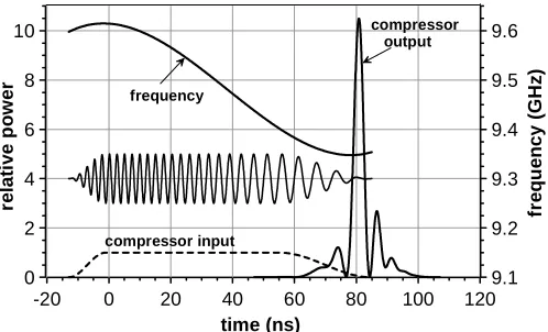
A voltage sweep corresponding to a frequency sweep of 9.87 – 8.51 GHz in about 300ns was used to sweep the solid-state source. Only frequencies below 9.6GHz and above 9GHz are useful, as above 9.6GHz the group velocity increases with frequency and below 9GHz the group velocity is approximately constant with frequency. However the driving voltage pulse to the so urce sweeps a larger voltage sweep in a longer time so that the pulse shape is close to that of optimum compression. A section of this pulse was amplified to 1kW by triggering a TWT, giving in a 70ns pulse with frequency sweep of 9.6 to 9.35GHz. Experimental optimisation of the start and stop frequencies as well as duration of the input pulse resulted in a compressed pulse of 3 ns duration with a peak power compression ratio of 10.9 (10.4 dB). This pulse excluding the side lobes contained 44% of the energy of the input pulse.
The theoretical model of the compression of microwave pulses was devised using a Fourier optics approach. A similar input pulse shape to the T WTs output pulse was used with this frequency sweep in the model. The model was found to give good agreement with the measured compressed pulse, both in shape and maximum compression ratio. A comparison of the experimental and theoretical compression results are presented in Figure 6 and Figure 7.
VII. POSSIBILITY OF COMPRESSION OF A PULSE FROM A
RELATIVISTIC VOLTAGE-TUNED BWO
For a helical compressor the optimum negative frequency sweep can quite naturally be realized at th e falling edge of an X-band relativistic BWO pulse using e.g. the decay of a Marx bank. The possibility of such frequency tuning by modulation of the electron energy is clearly evident from the BWO dispersion relation. However capabilities of a relativistic BWO in this aspect should be analyzed in m ore details including such important factors as DC and AC space charge, influence of the fundamental spatial harmonic, finite value of the guiding magnetic field etc. especially since previous theoretical and experimental BWO studies were mostly concentrated on realization and optimization of single frequency or mechanically tunable oscillators [11, 12].
As a result of special stuies using 2D and 3D versions of time-domain PIC code KARAT [13] a BWO configuration was found which combines high o utput power, high efficiency and a sufficiently wide frequency tuning for a moderately relativistic electron beam. According to the computer modelling, during a time period of 60 ns when the voltage almost linearly drops from 600kV to 300kV and the beam current drops from 4 kA to 2.5 k A, the BWO ou tput power reduces from 800 MW to about 300 MW an d its oscillation frequency changes f rom 10 GHz to 9.5 GHz. A helical-waveguide compressor’s parameters were then optimized to get a maximum power compression of the BWO frequency modulated pulse. The resulting compressed pulse in the simulations had a half-power level duration of about 2 ns and a peak power of 9.3 GW (see Ref. [14] for more details).
VIII. CONCLUSION
Measurements of kilowatt pulses compressed in the helically corrugated waveguide obtained a maximum power compression ratio of 10.9. The helical compressor experiments conducted were the first of their kind to be carried out and are found to be in good agreement with theory.
Theoretical and experimental investigations of the dispersive properties of a circu lar waveguide with a helical corrugation on its inner surface were carried ou t. The analytical method of perturbations and numerical code MAGIC were used to theoretically calculate the d ispersion characteristics of the eigenwave. Two experimental methods using SNA and VNA were used to m easure the helically corrugated waveguide dispersion. All the methods were found to agree well with each other.
ACKNOWLEDGEMENTS
Fig. 1. Schematic dispersion diagram for a helically corrugated waveguide. Where W1 and W2 are the spatial harmonics of the operating eigenwave and Wu1 and Wu2 are the spatial harmonics of the spurious eigenwave.
Fig. 2. Schematic view of a waveguide with a three-fold right-handed helical corrugation.
1.4 1.5 1.6 1.7 1.8 1.9 2 2.1 2.2 2.3 2.4
axial wavenumber (cm-1)
8.4 8.6 8.8 9 9.2 9.4 9.6 9.8 10
fr
eq
ue
nc
y (
G
H
z
)
8.6 8.8 9 9.2 9.4 9.6 9.8 10
frequency (GHz)
0 0.1 0.2 0.3 0.4 0.5 0.6
grou
p
ve
lo
cit
y
/c
TE2,1
TE1,1
perturbation theory
SNA measurements
perturbation theory
SNA measurements
SNA MAGIC SNA MAGIC
single-frequency MAGIC (1)
a)
b)
Fig. 3. Dispersion characteristics for the compressor waveguide calculated using SN A Magic simulations and perturbation theory in comparison to SNA measurements.
1.4 1.5 1.6 1.7 1.8 1.9 2 2.1 2.2 2.3 2.4
axial wavenumber (cm-1) 8.6
8.8 9 9.2 9.4 9.6 9.8 10
fr
e
q
u
e
ncy (
G
Hz
)
8.6 8.8 9 9.2 9.4 9.6 9.8 10
frequency (GHz)
0 0.1 0.2 0.3 0.4 0.5 0.6
group vel
oci
ty/
c
VNA measurements
SNA measurements
VNA measurements
SNA measurements
SNA MAGIC
TE2,1(1)
TE1,1
8.6 8.8 9 9.2 9.4 9.6 9.8
frequency (GHz)
-180 -90 0 90 180
ph
as
e
(
de
gr
ee)
a)
[image:7.612.47.291.289.354.2]b)
Fig. 4. Dispersion characteristics for compressor waveguide 2 including the VNA measurements (insert shows the data from VNA before processing: including (solid line) and excluding (dashed line) an 8-period helix).
[image:7.612.46.286.403.728.2] [image:7.612.315.564.522.686.2]-4 -2 0 2 4 6
-20 0 20 40 60 80 100 120
time (ns)
0 2 4 6 8 10
compressor input (P~1 kW)
compressor output
re
la
ti
ve power
heterodyne signal from mixer (fLO=9.2 GHz)
mixer
vol
ta
g
[image:8.612.55.294.50.196.2]e (a.u.)
Fig 6 Pulse compression in the helically corrugated waveguide experimental results
0 2 4 6 8 10
-20 0 20 40 60 80 100 120
time (ns)
9.1 9.2 9.3 9.4 9.5 9.6
compressor input
compressor output
frequency
relati
ve p
ow
er
fr
equ
ency
(GH
z)
[image:8.612.50.299.235.386.2]REFERENCES
1. Applications of High-Power Microwaves, edited by A.V. Gaponov-Grekhov and V.L. Granatstein (Artech House, Boston, 1994).
2. M.K. Thumm and W . Kasparek, Passive High-Power Microwave Components, IEEE Trans. Plasma Sci., 30, 755 (2002).
3. R.A Bromley, B.E. Callan, Use of a waveguide dispersive line in an f.m. pulse-compression system, Proc. IEE, 114, 1967. p. 1213-1218
4. Samsonov, S.V., Phelps, A.D.R., Bratman, V.L., Burt, G., Denisov, G.G. et al.,Compression of frequency modulated pulses using helically corrugated waveguides and its potential for generating multi-gigawatt RF radiation, Phys. Rev. Letters92, 118301 (2004).
5. G.G Denisov, V.L. Bratman, A.W.Cross, W.He, A.D.R.Phelps, K.Ronald, S.V.Samsonov, and C.G.Whyte, Gyrotron Travelling Wave amplifier with a Helical interaction Waveguide, Physical Review Letters, 25, 1998, p. 5680 6. N. F. Kovalev, I. M. Orlova and M. I . Petelin, Wave transformation in a multimode waveguide with corrugated walls, Izv. Vyssh. Ucheb. Zaved. Radiofiz., 11 (5), 1968, p. 783-789
7. G.G. Denisov, M.G. Reunion, Corrugated cylindrical resonators for short-wavelength relativistic microwave oscillators, Izv. VUZov Radiofizika, 25, 562, (1982) [Radiophysics and Quantum Electronics, 25, 562, (1982)]. 8. S.J. Cooke, G.G. Denisov, Linear Theory of a W ide-Band Gyro-TWT Amplifier Using Spiral Waveguide, IEEE Trans. Plasma Sci., 26, 519, (1998). 9. G.G Denisov, V.L. Bratman, A.D.R.Phelps, and S.V.Samsonov, Gyro-TWT with a he lical Operating Waveguide: New Possibilities to Enhance Efficiency and Frequency Bandwidth, IEEE Transactions on Plasma Science,
26 (3), 1998, p. 508.
10. G. Burt, S.V. Samsonov, K. Ronald, G.G. Denisov, et al., Dispersion of helically corrugated waveguides: Analytical, numerical, and e xperimental study, Phys. Rev. E (to be published).
11. Gunin, A.V., Klimov, A.I., Korovin, S.D., Kurkan, I.K., Pegel I.V., Polevin, S.D., Roitman, A.M., Rostov, A.A., Stepchenko, A.S., Totmeninov, E.M., Relativistic X-Band BWO with 3-GW Output power, IEEE Trans. Plasma Sci.26, 1998, p. 326-331.
12. Kitsanov, S.A., Korovin, S.D., Kurk an I.K. et al., Broadband Frequency Tuning in a Gigawatt S-Band Relativistic BWO, Proc. 14th Int. Conf. on High-Power Particle Beams, 2002, pp. 259-262.
13. Tarakanov, V.P., User’s Manual for Code KARAT. Springfield, VA: BRA,
1992.
14. S.V. Samsonov, V.L. Bratman, G.C. Burt, Adrian W. Cross, G.G. Denisov, A. D.R. Phelps and K . Ronald, Generation and Compression of Frequency Modulated Pulses from a Relativistic BWO, Proc. 15th Int. Conf.
High-Power Particle Beams, June 18-23, 2004, Russia (to be published).
Graeme Burt was born in Glasgow, Scotland in 1979. He received the B.Sc. degree (Honours) in Physics from the University of Strathclyde, U.K., in 2001 and the Ph.D. degree in physics from the same institution in 2004.
He is no w a r esearch associate in the Cockcroft Institute, University of Lancaster, U.K.
Sergey V. Samsonov was born in A rzamas-16, U.S.S.R., (now Sarov, Russia) in 1966. H e received the M.S. degree with honors from the Advanced School of General and A pplied Physics, Nizhny Novgorod State University, Russia, and the Ph.D. degree in phy sics from the Institute of Applied Physics (IAP), Russian Academy of Sciences, Nizhny Novgorod, Russia, in 1989 and 1996, respectively.
He is currently a S enior Scientist at the IAP, Russian A cademy of Sciences, Nizhny Novgorod, Russia. His research interests include both theoretical and experimental study of high-power electron devices, in particular, cyclotron resonance masers.
Dr. Samsonov was awarded the Medal and P rize of the Russian Academy of Sciences for young scientists in 2000.
Alan D. R. Phelps received the B.A. degree with Honours in physics and the MA degree from Cambridge University, UK, in 1966 and 1970 respectively, and D.Phil. degree for plasma research from Oxford Universities, Oxford, U.K., in 1976. He founded a research group at Strathclyde University, Glasgow, U.K., in 1978, and be came a full Professor in 1993. He was the Head of Physics Department, Strathclyde University, from 1998-2001. Prof Phelps is a Fellow of the Institute of
Physics and the Royal Society of Edinburgh. His interests include high-power
free-electron radiation sources and plasmas.
Vladimir L. Brat man was born in Chir chik, Uzbekistan (former U.S.S.R.) in 1945. H e received the M.S. and P h.D. degrees in phy sics from Gorky State University, Gorky, U.S.S.R., in 1967 and 1977, respectively, and the Doctor of Science degree from Tomsk Institute of High-Current Electronics, Russia, in 1992.
millimeter- and submillimeter-wave-radiation for plasma diagnostics and ECRH.
Prof. Bratman was a member of the Editorial Board of the Collected Papers “Relativistic HF Electronics” (1979-1992). Now he is a member of the Editorial Board of the Journal “Radiophysics and Q uantum Electronics”. The title Soros Professor was conferred on V. L. Bratman in 1998 and 2000. V . L. Bratman was a Visiting Professor in several research institutions and participated in a number of international projects (Brazil, The Netherlands, Israel, UK, Japan, and Italy).
Kevin Ronald was born in Glasgow, Scotland. He received the B.Sc. degree (Honours) in phy sics from the University of Strathclyde, U.K., in 1992 and the Ph.D. degree in phy sics from the same institution in 1997.
He is now a r esearch fellow in the Physics Department, University of Strathclyde.
Gregory G. Denisov was born in 1956, in Gorky, U.S.S.R (now Nizhny Novgorod, Russia). He received the M.S. degree in radiophysics from Gorky State University, Gorky, U.S.S.R., in 1978 and the Ph.D. degree from the Institute of Applied Physics, Academy of Sc iences of t he U.S.S.R (from 1991, Russian Academy of Sciences), in 1985 and T he Doctor of Science degree in 2002.
His current position is the Head of the Gyrotron Division in the Institute of Applied Physics, Russian Academy of Sciences, Nizhny Novgorod, Russia. His main research interests include relativistic microwave oscillators and am plifiers (e.g. free electron masers and cyclotron autoresonance masers), transmission lines and antenna systems for high power microwave radiation, methods for measurement and control of wave beam parameters, powerful microwave sources for E CRH systems in fusion installations (gyrotrons) and technological setups.
In 1996, Dr. Denisov was awarded by the Prize from the Fusion Power Associates for Excellence in Fusion Engineering.
Wenlong He received the B.Sc. degree in physics in 1983 f rom Suchow University, China, the M.Sc. degree in accelerator physics from China Academy of Engineering Physics in 1988, and the Ph.D. degree in r elativistic electron beams and masers from the
Department of Physics, University of Strathclyde, U.K., in 1995. He is now a Senior Research Fellow in the Physics Department, University of Strathclyde. His main research interests include relativistic electron beams, CARM’s, FEL’s, and othe Gyro-devices.
Adrian W. Cross was born in 1966. H e received a B.Sc. degree (Honours) in physics from t he University of Strathclyde, U.K., in 1989 and a P h.D. degree in physics, also from Strathclyde, in 1993.
He became a lecturer at Strathclyde in 2001, hav ing previously held the position of senior research officer (1998 to 2001) and research fellow (1993 to 1998). In 2004 he was he was appointed to senior lecturer. He has been involved in various aspectsn of research on gyrotrons, CARMs, free electron lasers, superradiant sources and plasma applications.
Alan R. Young graduated from the University of Strathclyde with a B.Sc. in Physics in 1993. Staying at the University of Strathclyde he completed a MSc. in Information Technologies Systems in the Department of Computer Science in 1994, be fore returning to the Department of Physics to do a P h.D. His thesis on High Quality Electron Beams for CARMs was completed in 1998. He has since continued to work as a r esearch fellow at the University of Strathclyde on a variety of devices including the CARM and the gyro-TWT.
Konoplev Ivan was born in 1973 in Penza, Russia, USSR. He received the B.Sc. degree (in Physics) from the Nizhny Novgorod State University in 1994 and the M.Sc. degree in physics from the same institution in 1996. In 1997 he received the M. Phil degree in physics from the University of Strathclyde and the Ph.D. degree in physics from the same institution in 2001.