Experimental Study of Microwave Pulse Compression
Using a Five-Fold Helically Corrugated Waveguide
Liang Zhang, Sergey V. Mishakin, Wenlong He, Sergey V. Samsonov, Michael McStravick,
Gregory G. Denisov, Adrian W. Cross, Vladimir L. Bratman, Colin G. Whyte,
Craig W. Robertson, Alan R. Young, Kevin Ronald, and Alan D. R. Phelps
Abstract—This paper presents the experimental study of mi-crowave pulse compression using afive-fold helically corrugated waveguide. In the experiment, the maximum power compression ratio of 25.2 was achieved by compressing an input microwave pulse of 80-ns duration and 9.65–9.05-GHz frequency swept range into a 1.6-ns Gaussian-envelope pulse. For an average input power of 5.8 kW generated by a conventional traveling-wave tube, a peak pulse output power of 144.8 kW was measured corresponding to an energy efficiency of 66.3%.
Index Terms—Helically corrugated waveguides (HCWs), mi-crowave pulse compression, mode coupling.
I. INTRODUCTION
P
ULSE compression technology that converts long-dura-tion low-power pulses into short high peak-power pulses is commonly used in applications that require high peak power and pulsed operation, such as sonar and radar systems [1], [2]. Pulse compression can be used to improve the space and time resolution, as well as the signal-to-noise ratio of radar systems [3] and image brightness in multiphoton imaging systems [4]. It can also be used to generate intense ultra-short laser pulses for studying physical phenomena in short time scales [5]–[7].By compressing a multi-megawatt-long duration pulse with an appropriate compression ratio, it is possible to generate gi-gawatt-level microwave radiation, which is otherwise extremely difficult to realize. Gigawatt-level microwave radiation can be achieved by a frequency-swept multi-megawatt pulse generated by a high power vacuum electronic device acting as the input
Manuscript received September 01, 2014; revised November 14, 2014, December 15, 2014, and January 10, 2015; accepted January 12, 2015. This work was supported by the Engineering and Physical Sciences Research Council (EPSRC) U.K. under Research Grant EP/K029746/1 and by the Russian Foundation for Basic Research under Grant 10-02-00975.
L. Zhang, W. He, M. McStravick, A. W. Cross, C. G. Whyte, C. W. Robertson, A. R. Young, K. Ronald, and A. D. R. Phelps are with the Department of Physics, Scottish Universities Physics Alliance (SUPA), University of Strath-clyde, Glasgow G4 0NG, U.K. (e-mail: [email protected]; w.he@strath. ac.uk; [email protected]; [email protected]; colin. [email protected]; [email protected]; [email protected]; [email protected]; [email protected]).
S. V. Mishakin, S. V. Samsonov, G. G. Denisov, and V. L. Bratman are with the Institute of Applied Physics, Russian Academy of Sciences, Nizhny Nov-gorod 603950, Russia (e-mail: [email protected]; samsonov@appl. sci-nnov.ru; [email protected]; [email protected]).
Color versions of one or more of thefigures in this paper are available online at http://ieeexplore.ieee.org.
Digital Object Identifier 10.1109/TMTT.2015.2393882
source for a microwave pulse compressor based on a high-fold helically corrugated waveguide (HCW) [8].
The use of a metal waveguide as a dispersive medium to gen-erate high peak-power microwaves was proposed [9]. The prin-ciple is to use a swept frequency modulated pulse train with a monotonically increasing group velocity propagating through the waveguide. The tail of the pulse will overtake its leading edge, which results in pulse shortening and growth in power am-plitude if the losses are small. The maximum compression ratio happens at the exit of the waveguide where all the frequency components arrive at the same time. The compression ratio is calculated from the electromagnetic wave propagation along an isotropic dispersive medium and is given by
(1)
where and are the group velocities of the beginning and the end frequencies of the microwave pulse. To achieve a high compression ratio , the dispersive media requires operation over a wide frequency band to give a large with a large monotonic group velocity difference in the operating frequency band, which allows a large value. This provides the capability of supporting a long pulse width in a medium of specific length , as well as a low equivalent loss factor [9].
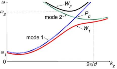
A smooth waveguide can also have a relatively large mono-tonic group velocity difference over a wide frequency range. From the dispersion curve of the smooth waveguide, the group velocity has a large change near the cutoff frequency (shown as and in Fig. 1) and the group velocity changes less at the frequencies further away from the cutoff frequency. There-fore, most of the frequency range suitable for the pulse com-pression is near the cutoff. However, the large ohmic loss close to cutoff prevents a high compression ratio being achieved re-sulting in low energy efficiency as evidenced by a compression ratio of 7 measured in an experiment using a 19.2-mm-diam-eter smooth 6.6-m-long circular waveguide at X-band [9]. The new HCW studied in this paper demonstrates much better per-formance than the smooth waveguide. The cross-sectional and longitudinal periodicities of an HCW allow new operating eigen modes ( and ) to exist by resonant coupling of modes 1 and 2 in the circular waveguide, as shown in Fig. 1. Around the coupling point , the group velocity of operating mode is monotonically decreasing over a relatively wide frequency band as frequency increases. also has a low ohmic loss at this frequency band as it is far from its cutoff. A further advan-tage of the HCW is that because the rapid change in group
Fig. 1. Mode coupling in the HCW. The eigenmodes and are the result of the coupling of modes 1 and 2 in the circular waveguide. The group velocity of operating mode is monotonically decreasing over a relatively wide fre-quency band as frefre-quency increases around the coupling point .
locity is achieved using an inflexion in the dispersion curve, an amplifier can be used as the input source. On the other hand, if the compressor operates at near cutoff frequency, then a big re-flection could occur due to a small difference in the waveguide diameter as a consequence of the tolerance achieved during ma-chining. The reflection may cause feedback oscillations and pos-sible damage to the amplifier. The use of the HCW can mitigate such risks.
The HCW has attracted significant interest and has been suc-cessfully used in the gyrotron traveling-wave amplifier TWA) [10], [11], and gyrotron backward-wave oscillator (gyro-BWO) [12]–[14] to improve the beam–wave interaction band-width in both types of devices. Thefirst pulse compression ex-periment using the HCW was carried out on a three-fold struc-ture. The spatial harmonic mode in the circular waveguide was chosen to couple with the mode to generate the oper-ating mode. Using these two low-order modes, the optimum fre-quency sweep signal was investigated and a compression factor of 25 in the peak power was obtained [15]. An 80-ns microwave pulse with an average power of 5.6 kW and a 5% frequency sweep in X-band was compressed into a Gaussian-shaped wave-form with a 1.5-ns full width at half maximum (FWHM) with a peak power of 140 kW. The maximum power-handling ca-pability of this 29.4-mm mean diameter three-fold HCW can be calculated from the maximumfield inside the HCW and the con-tinuous microwave breakdownfield. The power-handling ca-pacity of the three-fold HCW in air was calculated to be about 30 MW. Although in pulse operating mode the breakdownfield can be much higher than in continuous mode operation, about 1 MV/cm for 10-ns pulse duration [16], [17], it is still difficult to handle gigawatt-level microwave pulses as the power-handling capability is heavily dictated by the waveguide diameter. In this paper, the pulse compression experiment using afive-fold HCW with a larger average diameter of 65.7 mm for enhanced power handling is presented. The dispersion of and preliminary com-pression experiments based on thefive-fold HCW have been briefly reported in [18]. In this paper, the optimized experi-mental results are presented with comparisons to new simula-tion results from the microwave pulse compressor. Also, to give the readers a full picture of the experiment, the power-handling capability and the construction of thefive-fold HCW are
pre-II. DESIGN OF THEWAVEGUIDECOMPONENTS FOR
MICROWAVECOMPRESSION
The HCW was designed to have a mean waveguide diameter at least twice that of the three-fold one while operating in the same frequency range. High-order-mode operation was there-fore required and it was possible to achieve this by the coupling of the spatial harmonic mode with the mode, which determined a fold number of 5 for the HCW from the azimuthal synchronism condition to be satisfied, where and are the azimuthal indices of the two coupling modes and is the azimuthal period of the waveguide. and indicates an opposite rotation of the mode [19]. The dispersion characteristic can be changed by varying the HCW's geometry whose profile is governed by the
expres-sion in a cylindrical
co-ordinate system . The mean radius mainly decides the operating frequency range; the corrugated depth mostly controls the coupling strength, and the period directly affects the position of the coupling point. The design of the HCW for pulse compression requires accurate prediction of the dispersion curve as the group velocity is defined as .
A small change in the dispersion relation will cause a large difference when calculating the group velocity, especially when the HCW operates in the small range. Different methods have been developed to calculate the dispersion curve with dif-ferent accuracies and computing times, including the 1-D an-alytical method [19], [20], the specialized 2-D finite-element method (FEM) [21], and the full 3-Dfinite-difference time-do-main method (FDTD), or the FEM [22]. The 1-D analytical method is based on the method of perturbation. It is the fastest method and is useful for preliminary design and setting the pa-rameter range of the compressor, but is not accurate at large cor-rugation depths. The 3-D FEM simulation typically takes 4 h on a PC with a four-core processor at 2.8 GHz and 16-GB memory to simulate one period of thefive-fold HCW. It is not suitable for optimizing the parameters, however, it is able to provide the dynamicfield information inside the waveguide. The 2-D simulation based on a helicoidal coordinate transform provides a good balance between the accuracy and the computing time (5 min using the same hardware as compared to the 3-D case), although it is more complicated to develop the in-house code to implement an FEM solver with a helicoidal coordinate. The optimal dimensions used in the experiments were derived to
be afive-fold HCW with mm mm
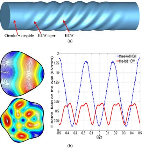
Fig. 2. (a) Simulation model in the CST Microwave Studio. (b) Electricfield and the electricfield on the wall of the three- andfive-fold HCW at 9.6 GHz.
The 3-D FDTD simulation code CST Microwave Studio was used to study the dynamic electric and magneticfields inside the HCW. In the simulation, the HCW was connected with a HCW taper whose corrugation is linearly reduced to zero and then followed by a circular waveguide, as shown in Fig. 2(a). A circularly polarized mode was stimulated at the input port for the three-fold HCW simulations and mode for the five-fold HCW to produce the desired operating eigenmodes. From the simulations, the maximum electric field inside the five-fold HCW was 0.7 kV/mm at 1-MW input power, which is 37.4% of the maximum electricfield in the three-fold HCW. The maximum power capability of thefive-fold HCW is about seven times higher as compared with the three-fold one oper-ating in the same frequency range. Fig. 2(b) shows the contour plot of the electricfields at the cross section of the three- and
five-fold HCWs, as well as the electricfield strength at the wall
of the three- andfive-fold HCWs.
[image:3.592.45.284.63.312.2]Compared with exciting the fundamental circularly polarized mode in the three-fold HCW, it is more complicated to ex-cite the circularly polarized mode in thefive-fold HCW. A mode convertor was therefore designed to transfer the input mode into the mode with sufficiently high mode conversion purity as well as low reflection at the oper-ating frequency band. The principle of operation is based on mode-selection Bragg scattering by a waveguide with a peri-odic corrugation. The mode convertor requires a high coupling coefficient between the incident and the output waves, which can be analytically calculated from the coupled mode theory based on the perturbation method. From the azimuthal synchro-nism condition, a fold number of 4 is required. The period of the mode convertor will satisfy the axial synchronism condition , where and are the axial wavenumbers of the mode and the spatial harmonic of the mode
Fig. 3. Connection and cross-sectional shape of the waveguide structures.
[23], [24]. The geometry was refined and verified by using the 3-D FDTD code CST Microwave Studio after the preliminary theoretical analysis. More than 95% of the power of the mode was converted into the mode in the frequency range of 8.9–9.9 GHz and the reflection coefficient of the mode is less than 30 dB. Thefive-fold HCW and the mode convertor both contain tapering sections, which linearly reduce the cor-rugated depth to zero, thereby converting from helical geome-tries into circular shapes to ensure the wave is smoothly converted to the operating eigenwave. The four-fold mode con-vertor requires a circular polarized wave as the input, therefore an elliptical polarizer was designed and constructed that was able to convert the polarization of the wave between linear polarization and circular polarization [25]. The center frequency was set at 9.3 GHz and it was able to achieve more than 98% energy conversion from one polarization to the other in a frequency band of over 10%. Four circular waveguide tapers (two at each side of the compressor) were used to match the different radii between the waveguide components as well as to cut off the undesired reflection for maintaining mode purity inside the waveguide. The connection of the waveguide struc-ture and the cross-section view of each component are shown in Fig. 3. At the other end of thefive-fold HCW, the same config-uration was used.
III. CONSTRUCTION AND MEASUREMENT OF
THEWAVEGUIDECOMPONENTS
Thefive-fold HCW and four-fold mode convertor were
con-structed separately. The inner surface of the HCW and the mode convertors were machined using facilities at Strathclyde Uni-versity, Glasgow, U.K., to manufacture positive aluminum man-drels using a four-axis computer numerical control (CNC) ma-chine with the copper grown on the aluminum by electroforming with a thickness of 6 mm. Finally, the aluminum was chemi-cally dissolved to leave the copper waveguides. The machined aluminum formers and thefinal copper waveguides are shown in Fig. 4. The waveguides were then carefully joined and tight-ened together. Care was taken to match the cross sections of the five-fold HCW pieces because of their irregular shape and to ensure the system was well aligned.
[image:3.592.306.547.64.170.2]Fig. 4. (a) Machined aluminum formers. (b) Final copper waveguides.
Fig. 5. Simulated and measured: (a) dispersion characteristics and group ve-locity and (b) losses of the pulse compressor.
22 to 9 if the dispersion of the other components besides the five-fold HCW is not taken into account. Therefore, the disper-sion characteristics of the whole waveguide structure that in-cludes all the waveguide components was measured using an Anritsu 37397A vector network analyzer (VNA). The simu-lated and measured dispersion characteristics, group velocity, and the losses are shown in Fig. 5. The difference of the disper-sion curve between the simulation and measurement is mainly caused by the machining tolerance of the waveguide compo-nents and the imperfect alignment of the waveguides. The sharp spikes in the measurement and simulation losses are due to small cavity effects of the elliptical polarizers and the mode conver-tors. The relatively large loss at the spike frequencies will result in smaller field amplitude at these frequencies. From (1), the losses will result in the reduction of the compression factor as
Fig. 6. (a) Schematic and (b) photograph of the microwave pulse compression experimental setup.
well as the energy efficiency. From the group velocity, the fre-quency band that can be used for compressing the microwave pulse was 9.05–9.65 GHz.
IV. PULSECOMPRESSIONEXPERIMENTALRESULTS
[image:4.592.45.284.64.162.2] [image:4.592.50.279.198.528.2]Fig. 7. Simulated and measured compressed pulses. The detail of the compres-sion factors for the different cases are shown in the inset.
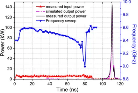
Fig. 8. Measured and simulated microwave outputs from the compression ex-periment and input microwave waveform and frequency sweep.
50-dB attenuation. The setup of the pulse compression exper-iment is shown in Fig. 6.
The compressed output voltage signals can be calculated quickly using the 1-D analytical simulation in which the microwave pulse propagation process in the compressor can be approximated as a plane wave moving forward along an isotropic dispersive medium, and the dispersive medium has an equivalent dispersion characteristic of the whole waveguide system. The 3-D FDTD simulation was also used to study the field evolution during the compression process. The output voltage signals from the 1-D analytical simulation, 3-D FDTD simulation, and the experimental measurement were analyzed to obtain the compression ratio. The experimental voltage signals were transformed into the complex values to get the phase information, as well as the imaginary part of the signal by using the inverse Fourier transform. The power of the sig-nals was then calculated from the complex values. The power compression factors for the three cases are 22.2, 21.5, and 21.9, respectively, and agree well with each other. The input signal and the compressed output signal are shown as Fig. 7. About 61.5% of the input energy was compressed into the main body of the output pulse and the pulse width was 1.9 ns (here it assumes the main body of the output pulse is a Gaussian-like waveform with a 1.9-ns FWHM).
By further adjustments on the frequency sweeping signal, like changing the frequency on the rising and falling edges of the pulse in the optimum frequency swept signal, or increasing the pulse duration, which means larger input energy, it was possible to achieve an even higher compression factor. For example, the best compression factor of 25.2 was obtained using a frequency sweeping signal with an 80-nsflat part in the pulse, with an av-erage power of the input pulse of about 5.80 kW, which resulted in a peak power of the compressed pulse of 144.8 kW with a pulse width of 1.6 ns, as shown in Fig. 8. For this compression ratio of 25.2, the energy conversion efficiency was measured to be 66.3%.
V. CONCLUSION
The paper has presented the operating principle, the design, and the experimental study of microwave pulse compression. To achieve a high power-handling capability, afive-fold HCW that operates at a higher order mode was employed. The dimensions of the HCW were initially studied using a 1-D analytical method based on the perturbation theory. They were further optimized by using the 2-D FEM based on the helicoidal coordinate trans-form, and the dispersion curve was verified by the 3-D FDTD code CST Microwave Studio and measurement of the disper-sion using a VNA. A compresdisper-sion ratio of 25.2 was achieved by compressing an input microwave pulse of 80-ns duration and 9.65–9.05-GHz frequency swept range into a 1.6-ns Gaussian-envelope pulse. As a result, a seven times greater power-han-dling capability was achieved as compared to the lower mode pulse compressor. The five-fold HCW provides a promising way to generate gigawatt-level microwave radiation by com-pressing multi-GW-level frequency-swept output power from relativistic backward wave oscillators. It advances thefield of ultra-high-power microwave pulse generation, which has a wide range of beneficiaries ranging from security screening to mate-rials testing.
REFERENCES
[1] A. V. Gaponov-Grekhov and V. L. Granatstein, Applications of
High-Power Microwaves. Boston, MA, USA: Artech House, 1994.
[2] P. B. Wilson, Z. D. Farkas, and R. D. Ruth, “SLED II: A new method of RF pulse compression,” inSLAC-PUB-5330 Linear Accelerator Conf., Albuquerque, NM, USA, Sep. 1990, pp. 204–206.
[3] J. R. Klauder, A. C. Price, S. Darlington, and W. J. Albersheim, “The theory and design of chirp radars,”Bell System Tech. J., vol. 39, no. 4, pp. 745–808, Jul. 1960.
[4] B. Vacano, T. Buckup, and M. Motzkus, “In situbroadband pulse com-pression for multiphoton microscopy using a shaper-assisted collinear SPIDER,”Opt. Lett., vol. 31, no. 8, pp. 154–1156, Apr. 2006. [5] R. Bartels, S. Backus, E. Zeek, L. Misoguti, G. Vdovin, I. P. Christov,
M. M. Murnane, and H. C. Kapteyn, “Shaped-pulse optimization of coherent emission of high-harmonic soft X-rays,”Nature, vol. 406, pp. 164–166, Jul. 2000.
[6] M. Nisoli, S. D. Silvestri, and O. Svelto, “Generation of high energy 10 fs pulses by a new pulse compression technique,”Appl. Phys. Lett., vol. 68, pp. 2793–2795, 1996.
[7] M. Nisoli, S. D. Silvestri, O. Svelto, R. Szipocs, K. Ferencz, C. Spiel-mann, S. Sartania, and F. Krausz, “Compression of high-energy laser pulses below 5 fs,”Opt. Lett., vol. 22, no. 8, pp. 522–524, Apr. 1997. [8] V. L. Bratman, G. G. Denisov, N. G. Kolganov, S. V. Mishakin, S.
[image:5.592.50.280.264.419.2]wide-band gyrotron traveling wave amplifier with a helically corru-gated waveguide,”Phys. Rev. Lett., vol. 84, no. 12, pp. 2746–2749, Mar. 2000.
[12] W. He, A. W. Cross, A. D. R. Phelps, K. Ronald, C. G. Whyte, S. V. Samsonov, V. L. Bratman, and G. G. Denisov, “Theory and simula-tions of a gyrotron backward wave oscillator using a helical interaction waveguide,”Appl. Phys. Lett., vol. 89, 2006, Art. ID 091504. [13] W. He, K. Ronald, A. R. Young, A. W. Cross, A. D. R. Phelps, C. G.
Whyte, E. G. Rafferty, J. Thomson, C. W. Robertson, D. C. Speirs, S. V. Samsonov, V. L. Bratman, and G. G. Denisov, “Gyro-BWO exper-iments using a helical interaction waveguide,”IEEE Trans. Electron Devices, vol. 52, no. 5, pp. 839–844, May 2005.
[14] W. He, C. R. Donaldson, L. Zhang, K. Ronald, P. McElhinney, and A. W. Cross, “High power wideband gyrotron backward wave oscillator operating towards the terahertz region,”Phys. Rev. Lett., vol. 110, Apr. 2013, Art. ID 165101.
[15] M. McStravick, S. V. Samsonov, K. Ronald, S. V. Mishakin, W. He, G. G. Denisov, C. G. Whyte, V. L. Bratman, A. W. Cross, A. R. Young, P. MacInnes, C. W. Robertson, and A. D. R. Phelps, “Experimental results on microwave pulse compression using helically corrugated waveguide,”J. Appl. Phys., vol. 108, no. 5, 2010, Art. ID 054908. [16] A. V. Gunin, A. I. Klimov, S. D. Korovin, I. K. Kurkan, I. V. Pegel,
S. D. Polevin, A. M. Roitman, V. V. Rostov, A. S. Stepchenko, and E. M. Totmeninov, “Relativistic X-band BWO with 3-GW output power,” IEEE Trans. Plasma Sci., vol. 26, no. 3, pp. 326–331, Jun. 1998. [17] G. A. Mesyats and D. I. Proskurovsky, Pulsed Elect. Discharge in
Vacuum. Berlin, Germany: Springer-Verlag, 1989, p. 256. [18] L. Zhang, A. W. Cross, W. He, C. G. Whyte, M. McStravick, A. R.
Young, K. Ronald, C. W. Robertson, A. D. R. Phelps, S. V. Samsonov, S. V. Mishakin, V. L. Bratman, G. G. Denisov, and N. G. Kolganov, “Theory and experiments on pulse compression using afive-fold he-lically corrugated waveguide,” in37th Int. Infrared, Millimeter, and Terahertz Waves Conf., Wollongong, N.S.W., Australia, Sep. 23–28, 2012, Art. ID Thu-Pos-21.
[19] L. Zhang, W. He, K. Ronald, A. D. R. Phelps, C. G. Whyte, C. W. Robertson, A. R. Young, C. R. Donaldson, and A. W. Cross, “Multi-mode coupling wave theory for helically corrugated waveguide,”IEEE Trans. Microw. Theory Techn., vol. 60, no. 1, pp. 1–7, Jan. 2012. [20] G. G. Denisov and M. G. Reznikov, “Corrugated cylindrical resonators
for short-wavelength relativistic microwave oscillators,”Radiophys. Quantum Electron., vol. 25, no. 5, pp. 407–413, 1982.
[21] S. V. Mishakin and S. V. Samsonov, “Analysis of dispersion and losses in helically corrugated metallic waveguides by 2-D vectorfi nite-ele-ment method,”IEEE Trans. Microw. Theory Techn., vol. 59, no. 9, pp. 2189–2196, Sep. 2011.
[22] G. Burt, S. V. Samsonov, K. Ronald, G. G. Denisov, A. R. Young, V. L. Bratman, A. D. R. Phelps, A. W. Cross, I. V. Konoplev, W. He, J. Thomson, and C. G. Whyte, “Dispersion of helically corrugated waveguides: Analytical, numerical, and experimental study,” Phys. Rev. E, Stat. Phys. Plasmas Fluids Relat. Interdiscip. Top., vol. 70, 2004, Art. ID 046402.
[23] M. Thumm, “High-power millimeter-wave mode converters in over-moded circular waveguides using periodic wall perturbations,”Int. J. Electron., vol. 57, no. 6, pp. 1225–1246, 1984.
[24] D. B. McDermott, J. Pretterebner, C. K. Chong, C. F. Kinney, M. M. Razeghi, and N. C. Luhmann, Jr., “Broadband linearly polarized
beat-wave mode converters,”IEEE Trans. Microw. Theory
Techn., vol. 44, no. 2, pp. 311–317, Feb. 1996.
[25] L. Zhang, C. R. Donaldson, and W. He, “Design and measurement of a polarization convertor based on a truncated circular waveguide,”J. Phys. D, Appl. Phys., vol. 45, 2012, Art. ID 345103.
main research interests include pulse-power technology, and gyrotron traveling wave amplifier (TWA)/backward-wave oscillators.
Sergey V. Mishakinwas born in Gorky, Russia, in 1984. He received the M.S. degree in plasma physics from the Advanced School of General and Applied Physics, Nizhny Novgorod State University, Nizhny Novgorod, Russia, in 2007. He is currently a Junior Research Fellow with the Institute of Applied Physics, Russian Academy of Sciences (RAS), Nizhny Novgorod, Russia. His scientific interests include vacuum microwave electronics and computational electromag-netics.
Wenlong Hereceived the B.Sc. degree in physics from Soochow University, Jiangsu, China, in 1983, the M.Sc. degree in accelerator physics from the China Academy of Engineering Physics, Chengdu, China, in 1988, and the Ph.D. degree in relativistic electron beams and masers from the University of Strathclyde, Glasgow, U.K., in 1995.
He is currently a Senior Research Fellow with the Department of Physics, Scottish Universities Physics Alliance (SUPA), University of Strathclyde. His main research interests include relativistic electron beams, gyrotron traveling-wave amplifier (TWA)/backward-wave oscillators, cyclotron autoresonance masers (CARMs), free-electron lasers (FELs), and other high-power microwave and terahertz devices.
Sergey V. Samsonovwas born in Arzamas-16, Gorky Region, Russia, in 1966. He received the M.Sc. degree from the Advanced School of General and Applied Physics, Nizhny Novgorod State University, Nizhny Novgorod, Russia, in 1989, and the Ph.D. and Dr. of Science degrees in physics from the Institute of Applied Physics, Russian Academy of Sciences (RAS), Nizhny Novgorod, Russia, in 1996 and 2007, respectively.
He is currently the Head of a research group within the Electronic Devices Department, Institute of Applied Physics, RAS. His main activityfields include high-power electron devices, particularly cyclotron resonance masers.
Michael McStravickreceived the B.Sc. (with honors) degree in physics, M.Sc. degree in high-power RF science and engineering, and Ph.D. degree in physics from the University of Strathclyde, Glasgow, U.K., in 2006, 2007, and 2012, respectively.
His main research interests include pulse compression technology and gy-rotron devices.
Gregory G. Denisovwas born in Gorky, U.S.S.R. (now Nizhny Novgorod, Russia), in 1956. He received the M.S. degree in radiophysics from Gorky State University, Gorky, U.S.S.R., in 1978, and the Ph.D. and Dr.Sc. degrees from the Institute of Applied Physics, Academy of Sciences, Nizhny Novgorod, U.S.S.R (since 1991, the Russian Academy of Sciences, Nizhny Novgorod, Russia), in 1985 and 2002, respectively.
of wave beam parameters, powerful microwave sources for electron cyclotron resonance heating (ECRH) systems in fusion installations (gyrotrons), and technological setups.
Dr. Denisov was the recipient of the Fusion Power Associates for Excellence in Fusion Engineering Prize in 1996.
Adrian W. Crossreceived the B.Sc. degree (with honors) in physics and Ph.D. degree from the Uni-versity of Strathclyde, Glasgow, U.K., in 1989 and 1993, respectively.
In 1993, he joined the Atoms, Beams, and Plasmas Group, University of Strathclyde, initially as a Re-search Fellow, and then became a Lecturer in 2000, a Senior Lecturer in 2003, a Reader in 2006, and a Professor in 2014 with the Department of Physics. From 2002 to 2007, he was an Engineering and Phys-ical Sciences Research Council (EPSRC) Advanced Fellow and has been a Group Leader since 2014. He has been involved in var-ious aspects of research on gyrotrons, cyclotron autoresonance masers, free-electron lasers, superradiant sources, gyrotron traveling-wave amplifiers, and plasma applications. More recently, he has primarily been concerned with re-search on microwave pulse compression, terahertz radiation sources, and pseu-dospark physics.
Vladimir L. Bratman was born in the former U.S.S.R (now, Chirchik, Uzbekistan), in 1945. He received the M.S. and Ph.D. degrees in physics from Gorky State University, Gorky, U.S.S.R., in 1967 and 1977, respectively, and the Dr. Sc. degree from the Tomsk Institute of High-Current Electronics, Tomsk, Russia, in 1992.
From 1970 to 1974, he was a Member of the Technical Staff with the Gorky Research Institute, “Salyut,” Moscow, Russia. In 1974, he joined the Gorky Radio Physical Research Institute, and in 1977, the Institute of Applied Physics, Russian Academy of Sciences, Nizhny Novgorod, Russia. Since 1985, he has been Head of the Short-Wavelength Relativistic Devices Group. In 1992, he be-came a Professor with the Advanced School of General and Applied Physics, Nizhny Novgorod State University, Nizhny Novgorod, Russia. His current re-search interests include high-power radiation from cyclotron resonance masers (including gyrotrons and cyclotron autoresonance masers) and from free elec-tron lasers, as well as the development of powerful sources of millimeter- and submillimeter-wave radiation for plasma diagnostics and electron cyclotron res-onance heating (ECRH). He was a Visiting Professor with several research in-stitutions and has participated in a number of international projects (Brazil, The Netherlands, Israel, U.K., Japan, and Italy). The title Soros Professor was con-ferred on him in 1998 and 2000.
Prof. Bratman was a member of the Editorial Board ofCollected Papers Rel-ativistic HF Electronics(1979–1992). He is currently a member of the Editorial Board ofRadiophysicsandQuantum Electronics.
Colin G. Whytewas born in Selkirk, U.K., in 1969. He received the B.Sc. degree in physics from the Uni-versity of Glasgow, Glasgow, U.K., in 1991, and the M.Sc. degree in laser physics and pulsed-power tech-nology and Ph.D. degree in physics from the Univer-sity of St. Andrews, St. Andrews, U.K., in 1992 and 1996, respectively.
Since 1996, he has been with the University of Strathclyde, Glasgow, U.K., with the Atoms, Beams and Plasmas Group (ABP Group), Department of Physics, where he is currently a Senior Research Fellow affiliated with the Scottish Universities Physics Alliance (SUPA). His research interests include the design and experimental investigation
of high-power broadband microwave amplifiers and oscillators, including novel helical gyrotron traveling-wave-tube (gyro-TWT) devices and re-verse-guide-field free-electron lasers, and RF systems for muon ionization cooling. He also designs and builds high-voltage pulsed-power supplies.
Craig W. Robertsonwas born in Ayrshire, U.K., in 1977. He received the B.Sc. degree (with honors) in physics and Ph.D. degree from the University of Strathclyde, Glasgow, U.K., in 1999 and 2004, re-spectively.
He is currently with the Department of Physics, Scottish Universities Physics Alliance (SUPA), Uni-versity of Strathclyde. His interests include low-tem-perature plasma production and diagnostics, as well as high-power microwave sources.
Alan R. Youngreceived the B.Sc. degree in physics, M.Sc. degree in information technologies systems, and Ph.D. degree from the University of Strath-clyde, Glasgow, U.K., in 1993, 1994, and 1998, respectively. His dissertation concerned high-quality electron beams for cyclotron autoresonance masers (CARMs).
He has since continued as a Research Fellow with the Department of Physics, University of Strathclyde, where he has been involved in a variety of gyro-de-vices, including CARM and gyrotron traveling-wave tubes (gyro-TWTs). He is also currently affiliated with the Scottish Universities Physics Alliance (SUPA), University of Strathclyde.
Kevin Ronaldwas born in Glasgow, U.K. He re-ceived the B.Sc. (with honors) and Ph.D. degrees in physics from the University of Strathclyde, Glasgow, U.K., in 1992 and 1997, respectively.
He is currently a Reader with the Department of Physics, University of Strathclyde, where he is affiliated with the Scottish Universities Physics Alliance (SUPA). His research interests include low-temperature plasmas, beam plasma and wave plasma interactions, geophysical plasma electrody-namics, microwave amplifiers and oscillators, and muon ionization cooling.
Dr. Ronald is a Member of the Institute of Physics (IoP), the European Phys-ical Society (EPS), and the American PhysPhys-ical Society (APS).
Alan D. R. Phelpswas born in Hampshire, U.K., in 1944. He received the B.A. degree (with honors) in physics and M.A. degree from Cambridge Uni-versity, Cambridge, U.K., in 1966 and 1970, respec-tively, and the D.Phil. degree from Oxford Univer-sity, Oxford, U.K., in 1970.
Since 1978, he has been with the University of Strathclyde, Glasgow, U.K., and became a Full Professor in 1993. His research interests include high-power free-electron radiation sources and plasmas.