RIT Scholar Works
Theses
Thesis/Dissertation Collections
1996
Infrared wireless communication
Noor Haq
Follow this and additional works at:
http://scholarworks.rit.edu/theses
This Thesis is brought to you for free and open access by the Thesis/Dissertation Collections at RIT Scholar Works. It has been accepted for inclusion
in Theses by an authorized administrator of RIT Scholar Works. For more information, please contact
Recommended Citation
School of Computer Science and Information Tedmology
Rochester Institute of Tedmology
Rochester, New York
Certificate of Approval
Masters'
Project
TIus is to certify that the Masters' Project of
NoorU.Haq
With a major
in
Computer Science
has
been
approved
by
the Project Committee as satisfactory
for the project requirement for the Master of Science degree
Thesis Committee:
Thesis Advisor
Graduate Program
O1air
I, Noor U. Haq, hereby grant pennission
to the Wallace Memorial Library of
R.I.T.
to reproduce my thesis in whole or in part.
Any reproduction will not be for commercial use or profit.
March 15,1996
Table
of
Contents
Revision Record
8
Abstract
10
1. Introduction
10
2.
Why
go wireless?
11
3. Types
of
wireless solutions12
3.1. Wireless local
area networks(LAN's)
12
3.1.1. Wireless LAN
topologies
13
3.1.2. Wireless LAN
technologies
15
3.2. Wireless
wide areanetworks(WANs)
16
3.2.1. Wireless
WAN
technologies
16
4.
Infrared
wireless communication17
4.1. Location
ofinfrared
wavesin
theelectromagneticspectrum18
42.
Brief
history
19
4.2.1.
Infrared Data Association
(IrDA):
19
4.3. IrDA
protocol model20
5. IrDA
serialinfrared
(SIR)
physicallayer
link
'22
5.1.
Serial infrared
(SIR)
physicallayer
features
22
5.1.1.
Point-to-point
overview22
5.1.2.
Environment
22
5.2. Media interface description
23
5.2.1. Physical
representation23
53. Media interface
specifications24
5.3.1.
Overall
link
24
5.3.2.
Active
outputinterface
26
5.3.2.1. Peak
wavelength26
5.322.
Maximum
and minimumintensity
in
angular range26
5.3.2.3. Half
Angle
26
5.3.2.4.
Signaling
rate27
5.3.2.5.
Rise time
Tr
andFall
time Tf
27
5.32.6. Pulse
duration
27
5.3.2.7. Optical
overshoot27
5.3.2.8
.Edge
jitter
27
5.3.3. Active
input
interface
27
5.3.3.1.
Maximum irradiance
in
angularrange28
5.3.32.
Minimum
irradiance in
angular range28
5.3.3.3.
Half
angle28
5.3.3.4.
Receiver
latency
allowance28
5.4. 1.152 Mb/s
modulationanddemodulation
28
5.4.2.
Encoding
scheme29
5.4.3. Frame
format
31
6.
IrDA
infrared
link
access protocol(IrLAP)
ln\
32
6.1. Data link layer
service specifications32
6.1.1.
Connectionless
services33
6.1.1.1.
Discovery
services33
6.1.1.2. Address
conflict services33
6.1.1.3. Unit
data
services34
6.1.2.
Connection
oriented services34
6.1.2.1.
Connect
services34
6.1.2.2.
Sniffing
services34
6.1.2.3.
Data
services34
6.1.2.4.
Status
services.34
6.1.2.5. Reset
services35
6.1.26
Disconnection
service35
6.2 Environmental
and operational characteristics35
621.
Configurations
andoperating
characteristics35
622. Data link
states35
62.3.
Unbalanced
data link
36
63. IrLAP frame
structure36
6.4. Frame
typeandframe function
37
6.4.1. Unnumbered format
(U)
37
6.4.2.
Supervisory
format
(S)
37
6.4.3.
mformationtransfer
format
(I)_
38
6.5 IrLAP operating
procedures38
7. IrDA link
managementprotocol(IrLMP)
im40
7.1. Architectural
overview41
7.1.1.
The
link
managementinformation
accessservice(LM-IAS)
41
7.12
Link
managementmultiplexer41
12
.Link
model41
72.1. Multiplexed
mode42
72.2.
Exclusive
mode42
73. Link
management multiplexer42
7.3.1. External interfaces
42
7.3.2.
Service
accesspoints,
connections and endpoints43
7.3.3. IrLMP
service specification44
7.3.3.1. Link
managementdiscovery
service primitives45
7.3.32 Link
managementlink
control service primitives45
7.3.3.3.
Link
managementdata
transfer
primitives46
7.3.4. Frame
formats
46
7.3.5.
Detailed
description
48
7.3.5.1. Station
control48
7.3.5.2. IrLAP
connectioncontrol50
7.3.5.3. LSAP-Connection
control7.4. Information
access service7.4.1. Information
model _7.4.2.
Service
primitives7.5.
Working
oftheinformation
access protocol8.
IrDA
transport
protocols(IrTP &
Tiny
TP)
8.1. Infrared Transport Protocol
(IrTP)[13]8.1.1. Problems
withouthaving
IrTP
.8.1.2. Purpose
ofIrTP
8.2.
Tiny
TP
9.
IrCOMM
andhow it
changesthe
currentprinting
model,
9.1. Current printing
model9.2. IrCOMM printing
model9.3. Differences between
thewired andtheIrDA
communicationmodel.9.4. IrCOMM
emulationservices9.4.1.
Raw
service9.4.1.1.
3-Wire
"raw"service
9.42.
Cooked
service9.4.2.1.
3-Wire
"cooked"service_
9.4.2.2. 9-Wire
"cooked"service
9.4.2.3.
Centronics
"cooked"service10.
Plug
andplay
(PnP)
extensionsto
link
managementprotocol.10.1.
Plug
andPlay
in IR devices
10.1.1.
Device identification
10.1.1.1. Device
discovery
10.1.12.
Device
identification
11. IrDA
based
productsin
the
market.11.1.
Laptops
11.2. Printers
andprinting solutions.113.
Operating
system11.4.
Electronic
organizers11.5. Test
suitsandtools _11.6. IrDA hardware
adapters andprotocolsoftware.12.
Infrared
wireless communication andits
competition12.1. Advantages
oftheIR
communication overRF
communication.12.2 Limitations
oftheIR
communication overRF
communication_13.
Conclusion
-The
future
ofIR14.
List of
acronyms15. References
81
List
of
Figures
Figure 1. Peer-to-peer LAN
topology
14Figure 2. Base-to-remote LAN
topology
15
Figure3. Theelectromagnetic spectrum
78
Figure 4. IrDAprotocol architecture 21
Figure 5. IRtransducermoduleinterfaces
23
Figure 6. Opticalportgeometry
26
Figure 7. Serial interactionpulse
(SIP)
29
Figure 8.
Encoding
schemefor 1.152 Mb/s datarate30
Figure9. Encoded datatransmission
by
the transmitter 31Figure 10. Frameformat 31
Figure 11. IrLAPprimitives usedtocommunicate withtheIrLMPand managethecommunications
processesbetween devices 33
Figure 12. IrLAPframeformat
37
Figure 13. IrLAP operatingprocedures
39
Figure 14. LinkmanagementinIrDAarchitecture 40
Figure 15. LM-MUXexternalinterfaces 43
Figure 16. LSAP
'-connections,
IrLAPconnections and stations 44 Figure1 7. Stationcontrol statetransitiondiagram 49 Figure 18. IrLAPconnection control statetransitiondiagram 51 Figure 19. LSAPconnection controltransitiondiagram 53 Figure20. Internalarchitectureoftheinformationaccess service(IAS)
54 Figure21. Current printingarchitecture (Adaptedfromthe "Page Description Languages: TheUps,
TheDownsandThePotentials"
[image:8.576.71.506.116.443.2]by
TaL.)
60Revision Record
Version #
Date
1.0
Sept.
11,
1995
2.0
Sept.
29,
1995
3.0
Oct.
9,
1995
4.0
5.0
6.0
Nov.
5,
1995
Nov.
26,
1995
Jan.
18,
1996
7.0
Feb.
4,
1996
8.0
Feb.
11,
1996
9.0
Feb.
18,
1996
Changes/Updates/Additions/Modifications
First
draft
versionCompleted
section6 (IrDA SIR
Physical Layer
link Modified
and updatedSection
2
and3
Added
the list
ofFigures
Incorporated
the
suggestionsfrom
project advisorA'isha Ajayi
in
section1,
2,
3
and5.
Renumbered
the
sections-Introduction
is
section1
whereasit
was2 in
version2.0
Updated
section6
(IrDA Infrared Link
Access
Protocol (IrLAP)).
Added
section5.1
andupdatedsections5.2
and5.3
Added
section7
explaining
the
IrDA
link
management protocol(IrLMP)
Added
section9
describing
the
IrCOMM
protocol andthe how
it
changesthe
existing printing
modelto
accommodateInfrared
based
printing.Section 10
examinesthe
IrDA
compatible productsin
the
marketCompleted
the section8
onInfrared
transport
protocol.Added
section10
explaining
Plug
andPlay
extensionto the
link
management protocol.Renumbered
section10
and11
to
11
and12.
Added
section12
explaining
Infrared
wireless communicationandits
competitionIncorporated
suggestionsfrom
project advisorA'isha
Ajayi
making adding
moreinfo,
correcting
typos
andcondensing fragmented
sections.Updated
the
entireReference
sectionAdded
the
section13
whichincludes
the
list
of acronyms.Renumbered
section13
of referencesto
section14.
10.0
March
1,
1996
Shortened
the
abstractand moved restto the
Introduction
sectionAdded
theworking
ofthe
IrLAP link
to the
section6.5 (IrLAP operating
procedure).Corrected
sometypos
andgrammaticalAbstract
Infrared
wireless communicationhas already
provento
be
commercial successin
the
Television
(TV)
andVideo
Cassette
Recorder
(VCR)
remote markets andis
poisedto
become
akey
technology
in
a number ofbusiness
markets.Over
the
nextfew
years,
wemay
witness anexplosive growth ofInfrared
based
"walk-up"
data
access and seamlessindoor
mobiledata
networking.The
protocol architecture proposedby
Infrared
Data
Association
(IrDA),
a non-profit organizationfounded
in
the
summerof1993,
is very
rapidly emerging
as anindustry
wideinfrared
standardfor
"walk-up",
point-to-point communicationThe
paper examinesthe
IrDA
protocol model andhow the
currentprinting
model canbe
modifiedto
work overtheIrDA
proposed protocolstack.1.
Introduction
Wireless
communicationis
the
process ofcomrnunicating
information
over adistance
through
free-space
instead
ofusing
a wire or other physicalmedium.This
can covermany
diverse
technologies.
Modulated
radiowavefrequencies
are usedto
broadcast
signals such asfor
television
or radio.It
canlikewise
mean radiatedtransmissions
between
andamong
antennasfor
two-way
orlimited-party
interactive
communications.Or it
can meanthe
useof sound waves such assonar,
infrared
signalsfor hand-held
television
remotecontrols or evenmodulated
laser
signalsfor
intersatellite
relaysin
space.[1]
Throughout
the
world,the
movementtowards
wireless communicationseemsirreversible. Wireless
communicationrepresents personal communications of
the 90's. Wireless
solutions providelogical
presencethrough
physical mobility.You
canstay
in
touch
wherever youare,
wheneveryou want.The
majorcUstinguishing
feature
of wirelesstelecommunications
as opposedto
wire communicationsis
that the
signalis
radiatedinto
free-space
ratherthan
confinedto
awire,
suchas a coaxial cable or afiber
opticlink.
[1]
This
feature
has
severalinherent
advantages.
Anyone
can receivethe signalin
the broadcast
areairrespective
of whetherthey
are at afixed
or mobile.New
links
canbe
established at a short notice and minimal cost overhead asno physicallinks have
to
be
installed.
.You
canstay
in
touch
whenever youwant,
whereveryouare.The disadvantage is
thatthe
wirelesssignals are spreadin
free-space
whichposses severelimits
onprivacy
of communications.Wired
communication
thus
restrictssignals while wirelessdoes
not.It is for
this
very
reason wireless signals shouldbe
low in
power sothat
they
canbe
confinedto
small zones.This
way
the
use ofthe
assignedfrequency
is
geographically
limited
to
a small zone andthe
same
frequency
canbe
reusedin
other zones.This
in
turn
effectively boosts
the
capacity
and effectivebandwidth
of wireless systems.Reuse
offrequency
is
criticalto the
growth anddevelopment
ofthe
wireless communicationin
the twenty-first
century.Starting
withabroad
overviewofthe
breadth
of wirelesscommunication,
the
paper presentsthe
key
reasonswhy
Wireless Communication is
becoming
increasingly
popularin
technologies
both
in
the
Wireless Local Area Networks
(LAN's)
andWireless Wide Area
Networks (WAN's).
The
majority
ofthe
paperfocuses
onthe
protocol architecture proposedby
Infrared Data
Association (IrDA). The
protocol architecture ofIrDA has
three
mandatory
compliancelevels
andthe
paper examinesthe
design
specifications ofthese
mandatory
levels. These
levels
are:Serial Infrared
(SIR)
Physical
Layer
Protocol
Infrared
Link
Access Protocol
(IrLAP)
Infrared Link Management Protocol
(IrLMP)
Besides
themandatory
compliancelevels
IrDA
standard providesnon-mandatory
solutionfor
Infrared Transport
Protocol
(IrTP)
andTiny
Transport Protocol
(Tiny
TP)
IrCOMM (the
emulation of serial and parallel ports overthe
IrLAP
andIrLMP)
Plug
andHay
(PnP)
These
solutionshave
alsobeen
explored and presentedinthe
paper.An
overview of someexisting
productswithinfrared
features
based
on theIrDA
functionality
has been
provided.Finally
a comprehensive critique on the completeIrDA
protocol architecture/
modelhighlighting
its
strengths and weaknesses as comparedwiththe
RF
communicationThe
paper concludeswitha subjective assessment ofthe
future
of theinfrared
technology.
2.
Why
go
wireless
?
Over the
last decade
companies such asBoeing
IBM Kodak,
Xerox
have downsized
andre-engineered
their
workforcein
orderto
be
costefficient,
productive andbetter
serve their customersneeds.One
ofthe majortrends
has been
to
move workforce out of their offices closerto the customers,
wherethey
can spend moretime
understanding
their
problems andproviding
solutions.Approximately
48
millionAmericans
alonehave
jobs
requiring
them to
be
"mobile"
muchof
the
time.
This
has
led
to
radical changesin
the
waysmany
of uswork,
andhas
created numerous challengesfor managing
a mobile workforce
andkeeping
it
productive.To
realize the expectedefficiency
gains,
a mobileworkforce requiresreliable,easy-to-use and
low-cost
way
to
accessinformation
from any
location For
many,
wireless communicationbest
satisfies all ofthese
needs.Increased Customer Satisfaction: Quick
responsetime
andthe
ability
to
spendmoretime
withcustomersusing
wireless communicationhelps increase
customersatisfaction
Reduced
cost:Each
year,
abouthalf
of all the companies relocate atleast
part oftheir
operations.
It
can cost as much as$2000
to
move an employee'sworkstation whichincludes
the
cost of moving,wiring
andinstallation
A
wirelessterminal
costsless
than
$500 for
acomparable move.[2]
Beside
the
costto
maintain a wirelessnetwork aresignificantly less
thanthe
wired network.Connectivity
wherepreviously
notfeasible:
The bulk
of the wireless systems arebeing
installed in
place ofdirect-cabled
networksbecause
the
location
ofthe
computing devices
(nodes)
makesrunning
wirefrom
the nodeto the
network expensive ortechnically
impossible.
The
following
situationsfall into
this
category:Older buildings
withstone or asbestos aredifficult
to
wireAdd
coverageto
common areas(like
conferencerooms)
wheregroups willbe
gathering
and whereLocal Area Network
(LAN)
connectivity
is
important
Leased
/
temporary
officesdo
notjustify
the
exorbitant cost ofinstalling
the
wired networkOver
wired- cabletrays
and conduits arefilled
to
capacity
Improved
user productivity:Provides
users withthe ability
to
viewe-mail,
call acustomer,
checkinventory
from
whereverthey
are.This
remote access ofinformation
provides quick responsetime
andincreases
productivity.Extension
of wiredLAN Connectivity:
Wireless
are alsobeing
installed
along
withthe
existing
wiredsystemsdue
to
thefollowing
reasons:As
backup
for
emergency
ordisaster recovery
situationsEasy
testing
ofthe
equipmentbefore
iri_talling
awired networkComplement
to
wiredLAN's
and applications3.
Types
of wireless solutions
There
aretwo
basic
type
of wireless solutions:Wireless local
area networks(LANs):
Wireless
wide area networks(WANs):
3.1. Wireless local
areanetworks
(LAN's)
Wireless
LANs
enablecommunicationbetween
shorterdistances
e.g. onebuilding
or aspeedsof
the
order ofMbytes
/
sec.Generally,
the
shorterthe
distance
(range)between
thenodes,
the
higher
the performance(speed).
Several
different
types
ofinfrared
andRF
systems canbe
usedfor
a wirelessLAN
extensions.
The
choice ofthe
systemis
normally
based
onthe
following
criteria:Physical
location
of the systemDistance
between
the
wirelessnode andthe
closest network pointThe
structural composition of thebuilding
in
whichthe
system willbe located
e.g.steel, concrete, metal,
plastic etc.Type
ofdata
that
willbe
exchangedbetween
the
nodes andthe
networkOther issues include
security,
networkmanagement,
performance and protectionfrom
interference
3.1.1. Wireless
LAN
topologies
There
aretwo types
of wirelessLAN
topologies
/
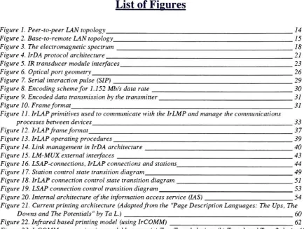
configurationsPeer-to-peer
topology
:This
topology
enablesthe
direct
communicationfrom
onedevice
to another,
withoutthe
needfor
going
through
anintermediate
device.
Peer-to-peer comrnunications
is especially
well suitedfor
adhoc ortemporary
networking
in
cases wherethe
employees movefrequently
orthe
business is housed
in
abuilding
witha short-termleases. This
topology
is
suitablefor
small,
collaborativeteams
working
in
closely
located
offices.Installing
such small networksis
fairly
easy
andfast.
Security
and network managementissues
are not resolved withthis
type
LAN.
Peer-to-peer
LANs
offer alimited
range of communications and coverage.However,
therange can
be
increased
by
using
an access point productto
attachthe
wirelessLAN
to
awiredLAN. The
wiredLAN
then
serves as a"backbone"
link
to
other access pointsand wireless peer-to-peer
LANs. If
you require aLAN
withbasic
functionality
in
an enclosedroom
aninfrared
LAN
withpeer-to-peerfunctionality
would mostlikely
be
thebest
choice.Peer-to-peer
Topology
[image:15.576.119.461.104.335.2],Wirelessworkstation
Figure 1. Peer-to-peer LAN
topology
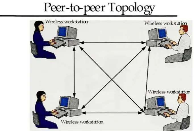
Base-to-remote
topology:
Another
wirelessLAN
topology
employsbase-to-remote
communications.These
networks use wirelessLAN
communicationsto
link
workstations
(remote)
to
a central workstations(base),
whichis
atthe
center of the wirelessLAN.
This
topology
workswellfor
commercial use and canbe
stand aloneBase-to-remote
Topology
Wirelessworkstation Wireless
[image:16.576.113.468.113.354.2]workstation
Figure 2. Base-to-remote LAN
topology
3.1.2.
Wireless
LAN
technologies
The
two choices are:Infrared: Infrared
(IR)
systems use a part ofthe
electromagnetic spectrumjust
below
visiblelight
asatransmission
medium.IR
technology
is
well suitedto
very high data
rates(~100Mbits/sec).
Radio
Frequency:
Radio
Frequency
(RF)
is
the
part of the electromagnetic spectrum whereelectronic signalstravel
as radio waves.Within
these
frequencies
communications canbe
achievedover a wide rangefrom the low
frequency
band
to
theextremely
high
frequency
band
[1]
.In
orderto
implement
RF
links
two
methods canbe
usedNarrowband
modulationtechnique
(NMT)
Spread-spectrum
technique
(SST)
NMT
have
problems with multipathtransmission
andthey
arevery
sensitiveto
interference,
soSST is
preferred.Among
SST's
the
mostpromising
is
codedivision
multiple access(CDMA).
In
this case,
a single codeis
assignedto
an emitterinside
acell;
if
the
emitter movesto
anothercell,
a new codeis
givento
continuetransmission
There
two
main choicesfor
RF
wirelesslinks that
canbe
usedfor
a point-to-pointtype
ofLAN. These
are:The first
oneis
the
unlicensedRF
solution offeredby
NCR,
O'Neill
andProxim. This
solution usesSST
in
the
unlicensedfrequency
band
of902-928 MHz. There
are concerns aboutthe
long
term
viability
ofthe
902-928 MHz
unlicensedband
because
in
additionto
unlicenseduse,
it is
also availableto
four
different
groups oflicensed
users.This
meansthat
the
unlicensed users must acceptany
and allinterference
generatedby
any
ofthe
licensed
users and must notinterfere
withthem.
Motorola
offersthe
othersolutionthat
operatesin
the
18
GHz
range andis licensed
by
theFederal
Communications
Commission (FCC). With
these systemsthe
usersdon't have
to
gamblewithRF interference
and can utilizethe higher
speed wireless connectionMotorola
offers anRF
wirelessLAN
referredto
asAltair. The
advantages ofthe
Altair
system are
that
Motorola
controlsthe
licenses
and canbetter
managethe
interference
potentials.Also
the
throughput
ofthe
systemis
about5.7
Mbps,
approaching
trueLAN
speeds
[6].
3.2. Wireless
wide area networks(WANs)
With
wirelessWAN's
you canconnectto
computers anywherein
theworld,providedaccess
is
allowed.In
mostcases,
interconnection
a wirelessWAN
is
accomplished witha wireless carrier orserviceprovider,whichcharges wirelessWAN's
users afee for
providing
the transport
service.Wireless WAN's
providetransrnission
distance
ofmany
miles,
but
atgenerally lower data
rates.3.2.1. Wireless WAN
technologies
There
aretwo
basic
types
of wireless service networks availablein
the
wide areaenvironment
Voice
service networks[3]: Although
these
networks are usedprimarily
for
voice,
data
canbe
accommodated.Specialized
mobile radio(SMR)
is
atwo-way
radio system operatedby
a commercialservice,
whichowns and mainbainsthe
base
station andholds
the
necessary
radiolicenses.
You
caneasily
subscribeto
anSMR
system.Cellular
telephone
systems use radio signalsto
connect mobile usersto
the
land-line
telephone
networkCellular
networks canbe
usedfor
voice,
data
andfax
transrnissions.
Subscribers
to
a cellular network are chargedbased
onthe
amountof
time
that
they
are connectedto
the
networkTherefore,
cellularis
well suitedfor
large
messages,
such asfaxes,
ratherthan
short ones.Personal
communicationservices(PCS)
is
adigital
servicethat
will enableData
service networks[3]:
These
networksinclude
traditional
radio-paging
networksandnetworks
that
use packet-radiotechnology.
Radio
Paging
wasoriginally
established asnon-speech, one-way,
personalselective
calling
withalert,
withoutmessage,
or withdefined
messages.Current
paging
systemsmay
include limited
capabilitiesfor
two-way
communication anddelivery
of short voice messages.Packet
radio networkssupporttwo-way
exchanges of short messages and arewell suited
for field-service
solutions.Information
is
transmitted
in
groups ofdata
called packets.Subscribers
are charged onthe
number of packetstrar_mitted.
Advanced
radiodata
information
service service(ARDIS)
is
a nationwide(USA
andCanada)
packet-radio networkthat
providestwo-way,
interactive,
real-timedata
communications.ARDIS
also providesdeep
m-building
coverage
from
coastto coast,
In
1993,
ARDIS
announced supportfor
automatic nationwideroaming,whichsupports wireless userswhen
moving
from
onecity
to another,
andARDISmail,
whichsupports wireless modemsand provides gateways
to
other mail systems.RAM Mobile Data
is
anational,
two-way
packet radio networkusing the
Mobitex
architecture,
whichis
managedby
the Mobitex
Operators
Association
RAM Mobile
Data
provideshost
connectivity,
connectivity
to
third-party
information
services,
andbroad
e-mail connectivity.Registration
is
automatic androaming
is
supported.Cellular digital
packetdata
(CDPD)
is
anoverlay
networkproviding
packetdata
over ananalog
cellular voiceinfra-structure.
Newly
announcedCDPD
transmission
products and servicesfrom
the
network providerswillprovide amore
reliable,
andpotentially
less
expensive,
solutionthan
fransmitting
over acircuitcellular
analog
network.Furthermore,
subscribers are expectedto
be
charged
for
only
the
number ofdata
packetstransmitted.
4.
Infrared
wireless communication
Infrared
canbe
thought
of as electromagneticenergy masquarading
asheat
[4]
It
has
physicalproperties
identical
to that
ofthe
radio andlight
wavesthe
maindifference,
however,
is
that
infrared
is
an electromagnetic wave with anextremely
shortwavelength.
[11]
Infrared
systems use a part ofthe
electromagnetic spectrumjust
below
visiblelight
as atransmission
medium.Infrared
systemsare anideal
choiceif
The distance between
the node andthe
rest ofthe
networkis
less
than800
feet
The
nodeis "line-of
sight"
to
a networkconnecting
point.Infrared
being
alight
medium
is
limited
to
a straight or"line-of-sight"
path
(like
the
TV
andVCR
remotecontroller).
If
the
data
to
be
transmitted
is
notvery large.
The
speed capabilities at present arelimited
to
242 KBps (kilobytes
/
second)
whichmay
notbe satisfactory
if
alarge
amount of
data
and graphics needto
be
movedto this
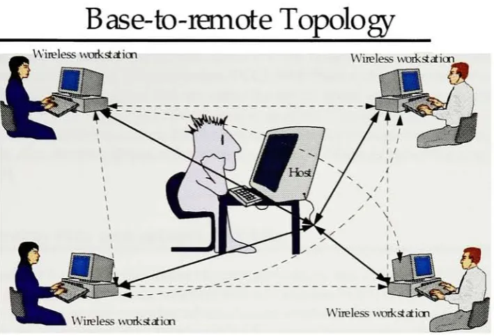
node.4.1. Location
ofinfrared
wavesin
the
electromagnetic
spectrumThe
electromagnetic spectrum extendsin
both
directions
from
the
visible regionThe
visible
light
spectrum rangesfrom
the
bright
redcolor at one endto
the
violetat the other.Red
light
has
the
longest
wavelengthandthe lowest
frequency
while violetlight has
the
shortest wavelength and
highest
frequency.
On
one side of visible region are theshorter-wavelength,
higher
frequency
light
rayswhichinclude
ultraviolet(UV),
x-rays andcosmic rays.The
other side of visibleregionarelonger-wavelength,
lower-frequency
light
rays whichfirst includes
infrared
light
andthen
as wavelengthsbecome
longer,
radio waves.[5]
Infrared has
anextremely
shortwavelength.Infrared
wavesareinvisible
and areusually
referred
to
asinfrared
light
orIR in
the
communication world.The
wavelength ofIR is
between 750
nm and3000
nmbut
the
IR
of greatestinterest
for
the
communicationis
known
asNear
Infrared,
so calledbecause its
rangeis
below
the
visiblespectrum,
whichsits
between 380
nm and750
nm.[4]
Frequency
(Hertz)
*+ ?
10 101 102 103 104 105 106 107icpio9 io^o11 iouio^io^io15!!)16io17io18
Audio MF
VMt<
Micro m
NearlR
[image:19.576.137.422.447.632.2]X Rays
Figure 3. The
electromagnetic spectrumassignments
to
worry
aboutUnlike
many
other wirelessdevices
thereis
a genuinepossibility
that
the
sameInfrared
device
canbe
usedanywherein
the world.Vendors
will appreciatethe
ability
to
design
andproduce one modelfor
distribution
inmultiple
countries.
[7]
4.2.
Brief
history
The
sunis
the
largest
generator ofIR,
UV
and othertype
of radiationVisible light
has
along history
as a means of wireless communicationFrom
mirrorsreflecting
sunlight signalsbetween
mountainsto
thefirst
transmission
ofhuman
voice over alight beam
in
1880
by
Alexander
Graham
Bell,
light
beam
communicationhas gradually
shiftedwithimprovements
in
technology
from
visiblelight
to
infrared.[4]
Most
of thelight
communication untilrecently has been
done
using
afocused beam
orline-of-sight
technique.
This
implied that
the
transmitting
beam had
to point,
orfocus
directly
onthe
receiver.But
withthe development
ofinexpensive
wide areaIR
light
detectors
andlight
emitting
diodes
(LED),
diffuse light
commtinicationhas become
possible.Over the
pastfew
years,
vendorshave
attemptedto
sellinfrared
data
cornrnunications productsin
avariety
of configurations.Photonics
Corporation
one ofthe
industry's
pioneers,enteredthe
market with a systemwhichthey
hoped
wouldreplace officecabling
by bouncing
infrared
beams
offthe
ceiling.A
company
calledUnTied
Telecom
developed
a point-to-pointinfrared
link
for replacing fiber
optic cablein
token
Ring
networks.Both
of these solutionsfrom Photonics Corporation
andUnTied Telecom
targeted
fixed
location
applications and met withlimited
success.[7]
Currently,
most ofthe
infrared
data
productsfocus
onportableapplications.Spectrix Corporation
has
developed
a system composed ofinfrared "access
points"
interconnectedvia an
Ethernet LAN
backbone
that
supports seamlessroaming for
users equipped with portableterminals.
Photonics
has
mtroduced
its Cooperative
andCollaborative
productfamilies
for
creating
spontaneous networks ofPersonal
Computer
(PC)
orMacintosh
compatible computers.One
oftheir
new products calledEtherpoint
also offers seamless roaming.IBM
has licensed Photonics
infrared
technology
andis
introducing
similar products.[7]
4.2.1.
Infrared Data Association (IrDA):
In
the
summerof1993,
the
Infrared Data
Association
(IrDA)
wasformed
and aligned withthe
Portable Computer
andCommunication
Association
(PCCA).[6]
The
charter ofthis
non-profit organizationis
to
develop
anindustry-wide infrared
standardfor
point-to-point communications.Within
less
than
ayearofits
founding
IrDA
releasedits
worldwide standarddefining
aninteroperable,
infrared
serialdata link
that
(initially)
supported speedof
115.2
Kilobits
per second(Kb
/
s)
at aminimumdistance
of one meter.Corporation
(DEC), Fujitsu,
General
Magic,
Hewlett-Packard
(HP),
International
Business
Machines
(IBM), Intel, Matsushita, Microsoft, Motorola, Siemens,
Sun
Microsystems
andToshiba.
Currently
IrDA
membership
represents over100
industry
leaders
in
computer andtelecommunication
hardware,
software,
component sector and producttesting.
Working
committeesheavily
usee-mail andfile
transfer
protocol(FTP)
onInternet Over 500 individuals E-mail
addresses are registered onthe
association's general communication reflectorwhichprovides abroadcast
of participant comments/
contributions andIrDA
announcementsto
all members.Amongst
all the membersTIP
andIBM have been
the
most prominent contributors.HP's
proposalfor the Serial Infrared
(SIR)
wasadopted overcompeting
submissionsfrom
Sharp
andGeneral Magic[7].
Work
is
currently going
onbetween
IBM,
Sharp
andHP
to
devise
the
standardfor
operation at4
Mbps (backward
compatibleto the
9600
-115 Kbps
speeds).
The
115.2
Kb
/
s speedis
sufficientfor
hransferring
smalldata,
but higher
speed(4
Mb
/
s)
is necessary for
trar_ferring
larger data.
With
major national andinternational
mobile computer systems providersto
embedfull
IrDA
functionality
in
mostfuture
productsmodels;
cross platform communicationbetween devices
shouldbe
possible.Applications
willexchangedata between different
brands
of computers and otherdevices
like
notebookPC's,
printers,
fax
machines, networknodes,
data
modems,
telephones,
automatedtellers,
personaldigital
assistants(PDA's),
electronic organizers and other portabledevices.
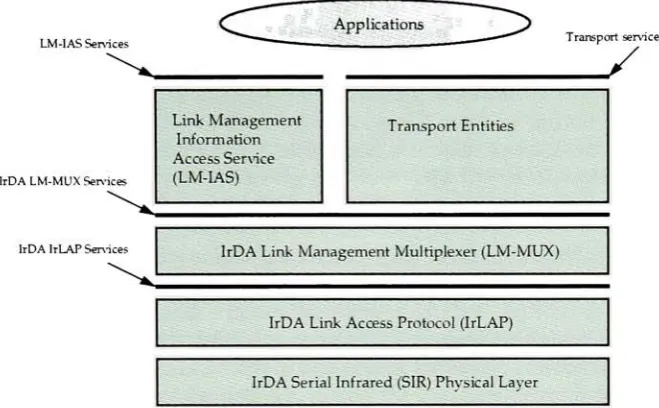
4.3.
IrDA
protocol modelThe LrDA's
wireless"point
andbeam"
data
transfer
is
simple yet compelling.It
provides aninteroperable,
low
cost,
low
power,
half duplex
serialdata
interconnection
standardthat
supportsawalk-up,point-to-pointusermodelthat
is
adaptableto
a wide range of appliances anddevices.[8]
IrDA
is
working hard
to
realizethe
ultimate goal-"if
it
works over awire
/
cableit
will workoverthe
IrDA
infrared
data
link".[9]
The IrDA
modelhas
three
mandatory
compliancelevels. Besides
the
mandatory
compliance
levels
IrDA
providesnon-mandatory
solutions/ levels.
The
mandatory
layers
correspondto
the open systeminterconnection
(OSI)
reference model and werederived
from
anexisting
industry
standard communication protocolslike
the High
level Data Link
Control (HDLC). Each layer
provides adifferent level
of abstraction and performs welldefine functions.
The
three
mandatory
compliancelevels
are:Serial
infrared
(SIR)
physicallayer
protocol[10]
(Refer
to
section5.0 for
details)
Infrared
link
access protocol(IrLAP) [11]
(Refer
to
section6.0
for
details)
LM-IAS Services
M3A LM-MUXServices
IrDA IrLAP Services
Applications
Transportservices
/
Link Management
Information
Access Service
(LM-IAS)
TransportEntities
IrDA Link Management Multiplexer(LM-MUX)
IrDA Link Access Protocol(IrLAP)
IrDA SerialInfrared(SIR)Physical Layer
Figure
4.
IrDA
protocolarchitectureBesides
the
mandatory
compliancelevels
IrDA
modelprovidesnon-mandatory
solutionfor:
Infrared
transport
protocol(IrTP) [13]
(Refer
to
section8.0
for
details)
Tiny
transport
protocol(Tiny
TP)
IrCOMM
(the
emulation of serial and parallelports over theIrLAP
andIrLMP) [14]
Plug
andplay
(PnP) [15]
[image:22.576.123.453.88.292.2]5.
IrDA
serial
infrared
(SIR)
physical
layer
link
[10]
The
physicalspecificationis intended
to
facilitate
the
point-to-pointcommunicationbetween
electronicdevices
(e.g.,
computers andperipherals)
using
directed half duplex
serial
infrared
communicationslinks
through
free
space.It
consists of an encoder/
decoder
(which
performsthe
IR
transmit
encoder andIR
receiverdecoder)
andthe
IR
transducer
(which
consists ofthe
outputdriver
andIR
emitterfor
transmitting
andreceiving
/
detecting).
The
encoder/
decoder interfaces
to the
Universal Asynchronous
Receive / Transmit
(UART)
is
expectedto
be
already
presentin
most computers.The IrDA-SIR
physicallayer link
specification[10]
takes
a standard asynchronousserial character stream
from
theUART (where
aframe
is defined
as a startbit,
8
data
bits,
no
parity bit
and astop
bit)
and encodesthe
output suchthat
0
represents apulse and1
represents no pulse.A
pulseis defined
asoccupying
a nominalrrunimumof1.6
microseconds
to
a maximumof3
/
16th
of abit
period, the
length
ofwhichis
inversely
proportional
to the
bit
rate ofthe
data
(i.e.,
slower thedata
ratelonger is
the
pulse).This
pulsestreamforms
the
input
to the
driver
for
the
Infrared
(IR)
emitterthat
convertsthe
electrical pulsesto
IR
energy.This
sectionspecifiesthe
optical mediainterfaces
and1.152
Mb
/
s and4.0
Mb
/
smodulation and
demodulation It
providesthe
specificationfor
the
activeinput interface
and active output
interface
andthe
overalllink Optical interface
specifications areindependent
oftechnology
andapply
overthe
entirelife
of thelink
and arereadily
testable
for
conformance.5.1.
Serial
infrared
(SIR)
physicallayer
features
5.1.1. Point-to-point
overviewThe
serialinfrared
link
supports opticallink length
from
zeroto
atleast
1
meterfor
accurate
(bit
error rate of1 in
109or
better)
in
free
space communicationbetween
two
independent
nodes.5.1.2.
Environment
There
arefour
ambientinterference
conditionsin
whichthe
receiveris
to
operatecorrectly.
Each
conditionis
to
be
applied separately.Electromagnetic
fields
of3V/m
maximumSunlight
of10 kilolux
maximumatthe
optical portIncandescent
lighting
of1000 lux
maximum5.2. Media interface description
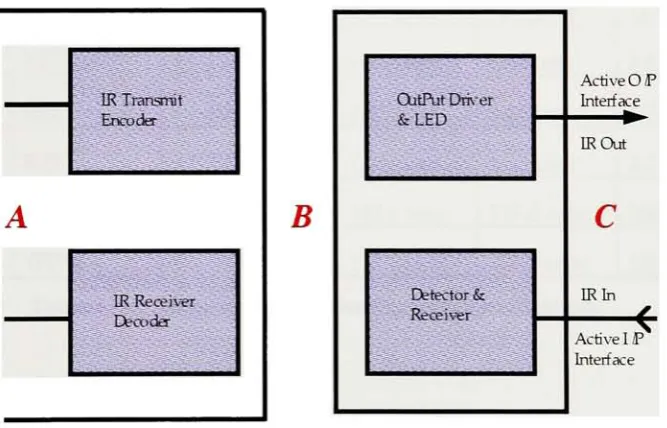
5.2.1. Physical
representationA
block diagram
ofthe
serialinfrared
link is
shownin
the
Figure
4.
The
electrical signalsto
the
left
ofthe
encoder/ decoder
at section"A
"are serialbit
streamsin
Figure 4. For
data
rates
up
to
andincluding
1.152
Mb
/
s,
the
optical signals at section" C"
are
bit
streamswith a
"0"
being
a pulse and a"1"
being
abit
period with no pulse.For 4.0
Mb
/
s a4 PPM
encoding
schemeis
used,
witha"1"
being
a pulse and a"0"
being
the
chip
withno pulse.The
electrical signals at section"B"
are
the
electrical analogs ofthe
opticalsignals atsection
"C".
For
data
ratesup
to
andincluding
1152
Kb
/
s,
in
additionto encoding, the
signal at section
"B"
is
organizedinto
frames
witha startbit,
8
data bits
and astop bit.
For
data
rateabove1152
Kb
/
s,
data
is
sentin
synchronousframes
consisting
ofmany
data bytes.
'-}: IR Transmit
Encoder
A
IK Receiver Decoder
B
ActiveOP Interface
:CutPutDriver
&LED;
IROut
c
IRIn ? Detector &
:". Receiver ;
[image:24.576.131.465.338.552.2]ActiveI P Interface
5.3. Media
interface
specifications
5.3.1. Overall link
The link length is
from
zeroto
atleast
1
meter.The distance is
measuredbetween
theoptical reference surfaces.
The
link
shall operate and meet thebit
error rate of1
in
109
or
better.
An IrDA
serialinfrared interface
must operate at9.6 Kb
/
sec.Additional
allowablerates
listed
below
are optional.Signaling
rate and pulseduration
specifications are shownin
Table 1.
Signaling
Rate (Ws)
Modulation
Rateoftolerance% ofRate
Pulse Duration Minimum Pulse Duration Nominal Pulse Duration Maximum
24Kb/s
RZI
+/-0.87
1.41
/usee78.13
usee88.55
iusec9.6Kb/s
RZI
+/-0.87
1.41
usee19.53
iusec22.13
iusec192Kb/s
RZI
+/-0.87
1.41
usee9.77
usee11.07
Msec38.4Kb/s
RZI
+/-0.87
1.41
Msec4.88
Msec5.96
usee57.6
Kb
Is
RZI
+/-0.87
1.41
Msec3.26
usee4.34
Msec1152 Kb
Is
RZI
+/-0.87
1.41
iusec1.63
iusec2.23
Msec1.152
Mb
Is
RZI
+/-0.01
147.6
nsec217.0
nsec260.4
nsec [image:25.576.65.514.214.480.2]40Mb/s
4PPM
+/-0.01
115.0
nsec125.0
nsec135.0
nsecTable 1.
Signaling
rate and pulseduration
specificationsFor signaling
rates<=115.2 Kb/s
Pulse duration
nominal =3
/
16
of
bit duration
Pulse duration
maximum =Pulse duration
nominal+
(greater
of2.5%
ofbit
duration
and
0.6)
Pulse duration
minimum =Pulse duration
nominal
for 115.2 Kb/s
signal*Rate
oftolerance
Example
ofcalculating
the Pulse duration
for
24
Kb
/
ssignaling
ratePulse duration
nominal =3
/
16
*1
/
2.4*103=
78.125
sec =
78.13
MsecPulse duratimmaximum
=78.13
+(greater
of2.5
/
100
*1
/
2.4*103or
0.6)
=
78.13
+(greater
of10.41
or0.6)
=
78.13
+10.41
=88.54
Msec
Pulseduration
minimum =3/16*115.2*0.87=
1.63
*0.87
=1.41
MsecExample
ofcalculating
the
Pulse duration
for
115.2
Kb
/
ssignaling
ratePulse
duration
nominal =3
/
16
*1
/
115.2*103=
1627
*10-6
=1.63
MsecPulse durationmaximum
=1.63
+(greater
of
2.5 / 100
*1
/
115.2*103or
0.6)
=
1.63
+(greater
of
0.21
or0.6)
=
1.63
+0.6
=2.23
MsecPulse
durationminimum
=3
/
16
*115.2
*0.87
=
1.63
*0.87
=1.4lMsec
For signaling
ratesof1.152 Mb/s
Pulse duration
nominal =25%
of
bit duration
Pulse duration
maximum =Pulse
duration
nominal+
8%
ofthe
bit duration
Pulse duration
minimum =Pulse duration
nominal-
5%
ofthe
bit duration
Example
ofcalculating
the
Pulse duration for 1.15 Mb /
ssignaling
ratePulse duration
nominal =1/4*1/1.152*106
s217
nsecPulse durationmaximum
=217
+(5
/ 100
+1
/
1.152*106)
=
217
+43.4
=260.4
nsecPulse durationminimum
=217
-(8
/
100
*1
/
1.152*106)
=
217
-69.44=
147
nsecFor signaling
ratesof4.0
Mb/s
Pulse duration
nominal =50%
of
bit duration
Pulse durationmaximum
=Pulse duration
iraminal+
8%
of thebit duration
Pulse duration
rruriirnum =Pulse duration
nominal
-8%
ofthe
bit duration
Example
ofcalculating
the
Pulse duration
for
4.0 Mb
/
ssignaling
ratePulse duration
nominal =1
/ 2
*1
/
4.0*106 =125
nsecPulse durationmaximum
=125
+(8
/
100
*1
/
4*106)
=
125
+10
=135
nsecPulse durationminimum
=125
+(8
/
100
*1
/
4*106)
5.3.2. Active
outputinterface
The
purpose ofthe
active outputinterface
(AOI)
is
to
emit aninfrared
signal.The
specified
AOI
parameters are:5.3.2.1. Peak
wavelengthWavelength
atwhichthe
optical output sourceintensity
is
amaximum.The
maximum andminimum values are
0.90
and0.85
respectively.These
valueshold
goodfor
alldata
rates.5.3.2.2. Maximum
andminimumintensity
in
angular rangeMaximum
intensity
in
angular rangeis the
power per unit solid angle andis
the
iraxirnumallowable source
intensity
withinthe
defined
angular range.Similarly
rninimumintensity
in
angular range
is
the
power per unitsolid angle andis
the
minimurnallowable sourceintensity
withinthe
defined
angular range.Both
are measuredin
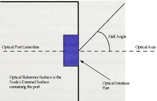
milliwatt per steradian5.3.2.3.
Half
Angle
The
half
angleis
measuredin
degrees is
the
half
angle of the cone whose apexis
atthe
center of
the
optical port and whole axisis
normalto
the surface of the port.The
half
angle value
is
determined
by
the
ntirumum anglefrom
the
normalto
the surface wherethe
minimum
intensity
in
angular rangeis
encountered.Ciptical Reference Surface isthe Node's External Surface containingtheport
CopticalInterface Port
Figure
6.
Optical
portgeometry
For
convenience, the
centerofthe
optical portis
taken
asthe
reference point wherethe
optical axis exits
the
port.The
maximumandthe
minimum values ofthe
Half-Angle is
+/
[image:27.576.161.422.407.574.2]5.3.2.4.
Signaling
rateThe
signaling
rate alsoknown
asthe
bit
rateis
the
rate atwhichinformation
is
sentorreceived.
It is
usually
measuredin kilobits
per second or megabits per second.Refer to
Table
1
for signaling
rate specifications.5.3.2.5. Rise
time Tr
andFall
time
Tf
Rise time
(Tr)
is
the time
intervals
for
the
pulseto
risefrom 10%
to
90%
ofthe
100%
value and
the
Fall
time
(Tf)
is
the
time
interval
for
the
pulseto
fall from 90%
to
10%
ofthe
100%
value.The
maximumTr
andTf
valuefor data
rates of115.2
Kb
/
s andbelow is
600
andthe
maximumTr
andTf
valuesfor data
rates above115.2
Kb
/
sis
40.
5.3.2.6. Pulse
duration
This is
the
duration
ofthe
opticalpulse,
measuredbetween 50%
amplitude points(relative
to the
100%
value,
not the overshootvalue),divided
by
the
duration
ofthe
bit
or symbolperiod
(depending
onthe
modulationscheme),
expressed as a percentage.This
parameteris
used as aduty
factor
conversionbetween
average and peak power measurements.Refer
to
Table
1.
for
the
pulsedurationvalues
maximurn,
norrdnal and ntinimumfor different
data
rates.5.3.2.7.
Optical
overshootOptical
over shoot(OOS)
percentage offull
(100%),
is
the
peak optical signallevel
abovethe
steady
statemaximum,
less
thesteady
statemaximum,
expressed as a percentage ofthe
steady
state maximum.The
maximumpercentagefor
alldata
ratesshouldbe
25%.
5.3.2.8.
Edge jitter
For
ratesup
andincluding
115.2
Kb
/
s,
thisis
the
maximumdeviation
withinaframe
of anactual
leading
edgefrom
the
expected value.The
expected valueis
aninteger
number ofbit duration's
(reciprocal
ofthe
signaling
rate)
afterthe
reference or start pulseleading
edge.
The
jitter
is
expressed as a percentage ofthebit duration
For
1.152
Mb
/s.TBD.
For 4,0 Mb /
s,
both
theleading
andtrailing
edges are consideredFrom
an eyediagram
the
edge
jitter is
the
spread ofthe
50%
leading
andtrailing
times.
The
jitter
is
expressed as a percentage ofthe
symbolduration
5.3.3.
Active input
interface
The
activeinput
interface
(AH)
detects
the
optical signalthat
strikesit
and conditions thereceiver
circuitry
andthen
outputsit
to
the
IR
receivedecoder.
The
specificationsfor
the
5.3.3.1. Maximum
irradiance
in
angular rangeMaximum irradiance
in
angular rangeis
the
power per unit area(measured in
milliwattsper square centimeter).
The
optical powerdelivered
to the
detector
by
a sourceoperating
at
the
maximumIntensity
in
Angular Range
at minimumlink length
must notcause receiver overdrivedistortion
and possible relatedlink
errors.If
placed atthe
Active
Output
Interface
reference plane of thetransmitter,
the
receiver must meetits bit
errorratio
(BER)
specificationThe
maximumIrradiance
in
Angular Range for
alldata
ratesis
SOOmW/an*.
5.3.3.2.
Minimum
irradiance
in
angular rangeMinimum irradiance
in
angular rangeis
the
power per unit area(measured
in
milliwatt ormicrowatt per square centimeter).
The
receiver must meetthe
BER
specification whileoperating
atthe
Minimum
Intensity
in Angular Range
into
the
minimum Half-Angle
atthe maximumlink length
Minimum
Irradiance
in Angular
Range for
data
rates of1152 Kb
/
s andbelow is 4.0
m
W/cm2andfor
data
ratesof115.2
Kb
/
s are10.0
m
W/cm2.
5.3.3.3.
Half
angleThe half
angleis
measuredin
degrees
andis
the
half
angle ofthe
cone whose apexis
atthe
center of
the
optical port and whose axisis
normalto the
surface ofthe
port.The
receivermust operate at the minimum
Irradiance
in Angular
Range from 0
angulardegrees (normal
to the
opticalport)
to
atleast
the
minimum angular range value.There is
nohalf
anglemaximum value
for
the
activeinput interface. The
link
must operate at anglesfrom
0
to
atleast 15 degrees.
5.33.4.
Receiver
latency
allowanceReceiver
latency
allowanceis
measuredin
milliseconds or microseconds andis
themaximum
time
after a nodeceasesIxari^mitting
before
the node's receiver recoversits
specified sensitivity.
The
maximum receiverlatency
allowancefor
alldata
ratesis 10
msec.5.4. 1.152
Mb/s
modulationanddemodulation
This
sectionofthe
IrDA
SIR
physicallayer link
describes
the
modulation anddemodulation
at1.152
Mb
/
sdata
rates.The
reasonthis
data
ratehas
been
chosento
explain
the
conceptis
because
the
encoding
scheme usedby
1.152
Mb /
sis
similarto
115.2
Kb
/
s.Both
use similar packetformat,
data
encoding,
cyclicredundancy
check(CRC),
andframe
format
whicharebased
on the opticalinterface
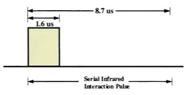
specification5.4.1. Serial
infrared interaction
pulsesTo
guaranteecompatibility
withslowerdata
rates(1152 Kb
/
s andbelow)
systems,
once aconnectionof speed
higher
that
115.2 Kb
/
sis
establishedthe
system must emit aSerial
lasts
to
quietthe
slower systemsthat
mightinterfere
withthe
link. The
pulse canbe
transmitted
immediately
after a packethas been
transmitted.
The
pulseis
shownin
figure
below.
1.6us
H
-8.7us
-Serial Infrared _
Interaction Pulse
H
Figure
7. Serial interaction
pulse(SIP)
5.4.2.
Encoding
schemeThe
1.152
Mb
/
sencoding
schemeis
similarto
that ofthe
lower
ratesexceptthat
it
usesone quarter pulse
duration
of abit
cellinstead
of3
/
16,
and usesHDLC
bit
stuffing
afterfive
consecutive onesinstead
ofbyte insertion The
following
illustrates
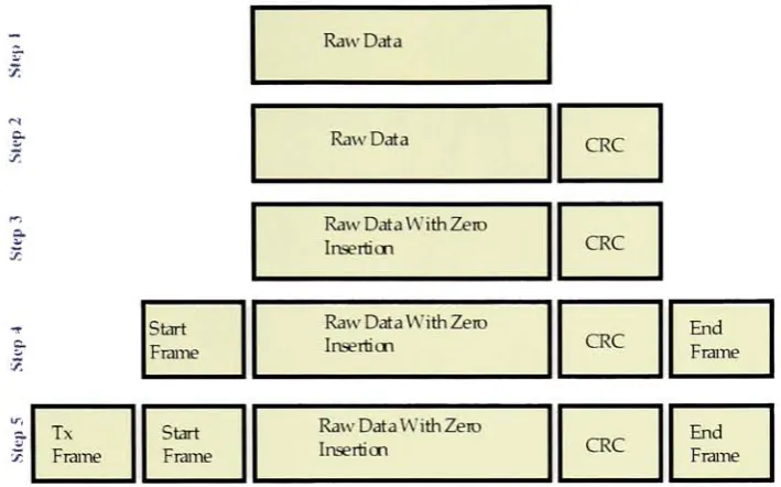
the order ofencoding.
Step
1 & 2
:The
rawtransmitted
data
is
scannedfrom
theleast
significantto the
most significantbit
of eachbyte
sent and a16
bit Cyclic
Redundancy
Check (CRC)-Comite
Consultatif International
de Telegraphique
etTeTephonique
(CUT)
is
computedfor
[image:30.576.203.391.157.254.2]a.
a.
7.
RawData
Raw Data CRC
Raw Data VY ith Zero
Insertion CRC
Start
Frame
RawDataWithZero
Insertion CRC
End
Frame
Tx
Frame
Start
Frame
Raw Data WithZero
Insertion CRC
End
Frame
Figure
8.
Encoding
schemefor 1.152 Mb/s data
rateStep
3:
A
zerois
inserted
afterfive
consecutive ones aretransmitted
in
orderto
distinguish
theflag
from data. Zero
insertion
is done
onevery
field
exceptthe
flags.
Step
4:
Beginning
andending flags
are appended at thebeginning
and endThe
flag
usedisTE'hex.
Step
5: An
additionalbeginning flag
is
added atthe
beginning. The
flag
usedis
'7E'
hex.
Refer
to
Figure
8.
for
encoding
steps1-5.
[image:31.576.120.475.58.279.2]NRZ
<1.152
Kbfe
1.152 Mbfe
1.6us
[image:32.576.129.396.79.263.2]lftbitcdl
Figure 9. Encoded data
transmission
by
the transmitter
5.4.3. Frame format
The
1.152
Mb
/
sframe
format
follows
the standardHDLC
format
exceptthat
it
requirestwo
beginning
flags,
an addressflag,
a controlflag
aninformation
flag,
aframe
checksequence
field
and a rmnimurnof oneending flag.
'7ETiex
is
usedfor both
the
beginning
and
ending
flags.
A
s
s
D
S
\
T
0
P
T
T
D
c
A
A
R
DATA
R
R
R
E
C
T
T
S
S
START - Start
flag,
'7E'hex
ADDREss -8 bit
addressfield
DATA - 8 bitcontrolfield+ upto2K-3 bytes
CRC -CCIT 16 bit Cyclic
Redundancy
CheckSTOP
-Ending
flag,'7E'hex
[image:32.576.136.451.487.682.2]6.
IrDA
infrared
link
access protocol
(IrLAP)
[11]
The infrared
link
access protocol(IrLAP)
ofthe
IrDA
standarddescribes
thefunctions,
features,
protocol and servicesfor
interconnection
between
computers at thedata link
layer (equivalent
to
the
layer
#
2 in
the
OSI
model).The
data
link
layer
protocolis
generally
referredto
asIrLAP
[11]
andis derived from
anexisting
asynchronousdata
communicationsstandard
(an
adaptation ofHDLC).
IrLAP
constitutes onelayer
in
ahierarchical
stack of communication protocollayers,
it
uses services providedby
thephysical
layer
and provides servicesto
thelayer
aboveit.
The
main services providedby
the
IrLAP
are:Set
dynamic
32
bit
physicaladdressesEncapsulate
all communicationsin
frames
with16
bit frame
check sequence(FCS)
thus
maintaining
data
transparency
Discover
devices
withinIR
spaceNegotiate
parametersfor
connectionsSetup
connectionsTransfer
data
-which
includes managing
windowsfor
reliabledata
transfer
andretranslating
on errorsReestablish
abroken
connectionManage time
outsClose
connection(link shutdown)
Manage
media access andturn
around rules6.1. Data link layer
service specificationsThis
section explainsthe
services providedby
the
data
link layer
to the
upperlayer.
The
services are specified
in
terms
of service primitives.IrLAP
employsfour
generictypes
ofservice primitives
(see Figure 10 for
graphicalrepresentation)
which are:Req
u estwhichis
passedfrom
the
layer
aboveit
(IrLMP)
to
invoke
a serviceIndication
whichis from
IrLAP
to the
layer
aboveit
(IrLMP)
to
indicate
an event orto
notify
an actioninitiated
by
IrLAP
Response
whichis
passedfrom
the
from
the
layer
aboveit
(IrLMP)
to
acknowledgesome procedure
invoked
by
anindication
primitiveConfirm
whichis
passedfrom
IrLAP
to the
layer
aboveit
(IrLMP)
to
convey
the
results of
the
previousservice requestIrLAP
providestwo
generaltypes
of services:Connectionless
Services
Connection-Oriented
Services
Upper Layer
(IrLMP)
Request Conil rm
IrLAP Layer
Frame(s)
Frame(s)
Physical
Layer
Upper
Layer
(IrLMP)
Response Indicatioii
!
1
IrLAP Layer
Frame(s)
Frame{s)
1Physical Layer
k
Figure 11. IrLAP
primitives usedto
communicatewiththe
IrLMP
and managethe
communications processes
between devices
6.1.1.
Connectionless
services6.1.1.1.
Discovery
servicesThe
discovery
servicesinclude
three
primitivesrequest,indication
and confirm.The
requestprimitive
is
usedto
find
outwhat,
is
any
devices
arewithincommunication rangeand are available
for
connections.A
list
ofthe
availabledevices
is
returnedwiththe
matching
confirmprimitive.A
device
that
is discovered
by
anotherdevice's
request primitiveissues
anunsolicitedindication
primitive withinformation
about thedevice
that
issued
the
request primitive.6.1.1.2.
Address
conflictservicesThe