solar gains through complex facades in building
simulation programs
For publication in Energy and Buildings
Tilmann E. Kuhn′, Sebastian Herkel′, Francesco Frontini′+′′,
Paul Strachan′′′, Georgios Kokogiannakis′′′
′Fraunhofer Institute for Solar Energy Systems ISE,
Heidenhofstr. 2, 79110 Freiburg, Germany
Phone: +49-761/4588-5 297 Fax: +49-761/4588-9 297
E-mail: [email protected]
http://www.ise.fraunhofer.de
′′ Politecnico di Milano, Dipartimento BEST
Via Bonardi 9 , 20133 Milano, Italy
′′′ ESRU, Dept. of Mechanical Eng., University of Strathclyde
Glasgow G1 1XJ, UK. http://www.esru.strath.ac.uk
Contents
1 Abstract 2
2 Introduction 3
2.1 Solar Control - general statements . . . 3
2.2 Evaluation of complex facade components . . . 4
3 The new method “black-box model” for building simulation programs 4 3.1 General . . . 4
3.2 Description of the model . . . 6
3.2.1 Input data . . . 6
3.2.2 Modelling of the centre-of-glazingU-value . . . 6
3.2.3 Determination of the total solar absorptanceαe,tot . . . 7
3.2.4 Calculation of the absorptance in the two virtual layers . . . 8
3.2.5 Treatment of diffuse irradiation . . . 9
3.2.6 Treatment of variable internal and external heat transfer coefficients . . 10
3.2.7 Treatment of thermal mass . . . 11
3.2.8 Treatment of back reflectance from the room . . . 12
3.3.1 Examples: External blinds . . . 12
3.3.2 Examples: Internal blinds . . . 13
4 Implementation of the black-box model in ESP-r 14
4.1 Description of the implementation . . . 14
4.2 Validation of the implementation . . . 14
5 Assessment of the impact of the new model implemented in ESP-r 15
6 Conclusion 16
Nomenclature
Angle definitions (numerical values of angles are specified in degrees throughout this publication):
γ facade orientation ( 0◦ := south, west positive )
γs solar azimuth angle ( 0◦ := south, west positive )
γf γf:=γs−γ (facade azimuth angle, 0◦ parallel to facade normal )
αs solar altitude angle
αp solar profile angle αp[αs, γf] = arctan tan(cos(αγs) f)
[6]
αin angle of incidence αin[αs, γf] = arccos cos(αs) cos(γf)
[6]
βk tilt angle of the slats of a venetian blind or - in the case of facades with switchable
properties - a parameter field which characterises the switching state
Properties of glazing and blind:
Axy, d, e z A= [τ / ρ/ α / g ] for
[ transmittance / reflectance / absorptance / g-value (or TSET or Solar Factor) ] x = [′ / nothing ] when [ radiation is incident on the inner surface / otherwise ]
y = [e / v ] for [ solar / light ] properties
d = [dif / nothing ] for [ diffuse irradiation / otherwise]
e = [ eff-m /eff-h ] for [ monthly / hourly ] effective (average) values
z = [ gzg / bld /tot or nothing ] for [glazing / blind / combination ]
Thermal resistances:
U U-value
Rx x = [e/i ] for [ external / internal ] convective and radiative surface resistances
and [ s] for the thermal resistance of the sample. 1/U =Re+Rs+Ri
Other:
Examples: ρ′
v,dif, gzg Diffuse light reflectance of the inner surface of glazing without blind
ρ′
gzg[λ] Spectral reflectance of the inner surface of glazing without blind
αtot[αs, γf] Total absorptance in the facade
gtot[αs, γf] Total Solar Energy Transmittance g of glazing and blind
ggzg[αin] Total Solar Energy Transmittanceg of glazing without blind
1
Abstract
This paper describes a new general method for building simulation programs which is intended to be used for the modelling of complex facades. The term ’complex facades’ is used to designate facades with venetian blinds, prismatic layers, light re-directing surfaces etc. In all these cases, the facade properties have a complex angular dependence. In addition to this, such facades very often have non-airtight layers and/or imperfect components (e.g. non-ideal sharp edges, non-flat surfaces, ...). Therefore building planners often had to neglect some of the innovative features and to use ´work-arounds´ in order to approximate the properties of complex facades in building simulation programs. A well-defined methodology for these cases was missing. This paper presents such a general methodology.
The main advantage of the new method is that it only uses measureable quantities of the transparent or translucent part of the facade as a whole. This is the main difference in comparison with state of the art modelling based on the characteristics of the individual sub-components, which is often impossible due to non-existing heat- and/or light-transfer models within the complex facade.
2
Introduction
2.1 Solar Control - general statements
Transparent components are essential to the design and performance of a building. They influence its indoor comfort and energy budget in many diverse ways: daylight illuminates indoor rooms throughout the year [1], solar energy can be used to heat buildings passively, excessive solar gains can cause glare and overheating. The amount of heat which enters modern buildings by conduction via opaque areas of the envelope is usually small due to the small temperature differences in summer and the level of thermal insulation which is already common in many countries. Conductive gains may still be relevant in warmer climates with less need for thermal insulation. For example, inadequately insulated roof areas in the older building stock present a main cause of solar gains in upper storeys: dark-coloured roofing materials are significant in increasing cooling loads in air-conditioned buildings during sunny summer days [29]. Dark-coloured facade claddings may also increase cooling loads especially in buildings with facade integrated openings for continuous ventilation. This paper concentrates on control of solar gains only; an overview of current work on glare protection for daylight conditions is given in [34]. The amount of transmitted heat, or solar gain, due to transparent areas of a building envelope is determined primarily by [28]:
• the size of the glazed areas
• the orientation of the glazed areas with respect to the sun
• external obstructions by surrounding buildings and trees
• the glazing properties
2.2 Evaluation of complex facade components
A combination of measurements and numerical models is the best choice for determining performances. Measurements are needed for validation. Modelling is needed in order to reduce the cost for the measurements by reducing the necessary number of measurements.
For the case of venetian blinds, the characterisation of glazing, blinds and combinations of glazing and blinds has been described in detail in [17] [18].
However, in many building simulation programs like for example [4], [8], [9] or [31] it is difficult to include the results of such facade measurements and facade simulations. A new solution to this problem is the topic of this paper.
3
The new method “black-box model” for building simulation
programs
3.1 General
The general idea is to create an interface for building simulation programs (e.g. [4], [8], [9] or [31]) or which allows the properties of complex facades to be integrated without any modelling of the details within the building simulation program itself. The reasons for this approach are the following:
• There are always new facades which are too complex for the internal models which are included in the building simulation program itself. It is important for the success of new developments that the advantages of innovations can be demonstrated by building designers. The lack of an interface for these new products often slows down the market penetration of new daylighting and solar-control systems.
models with sufficient accuracy. This is especially the case when the real component deviates significantly from the ideal design. An example could be a glazing unit with multiple integrated prismatic or light re-directing layers with imperfect edges and im-perfect surface flatness of the light re-directing surfaces.
• Semi-empirical models have been developed for facades with venetian blinds which are able to describe the angle-dependent properties of the facade accurately, without needing too many (expensive) measurements [17]. However, to study the impact of such complex facades on overall building performance, it is necessary to integrate these models into a building simulation program.
Therefore a method was implemented in a whole building simulation program which requires only data which is measurable on the complete glazing unit. As input, the new method needs only the angle-dependentg-value/solar factor and solar transmittance of the total facade unit. If available, the solar reflectance ρe (for solar radiation incident on the outer surface of the
facade unit) can also be used as input, which improves the accuracy of modelling the external surface temperature. It is important to notice that it is not always necessary to measure g, τe and ρe: in some cases these properties can be calculated with mathematical models, (for
example, with the models given in [17] for the case of facades with venetian blinds).
3.2 Description of the model
3.2.1 Input data
The starting point of the model is a set of measured or externally calculated values. Each data set iis valid for different directions of the incident light and different settings of the control parameterβk. The model needs the following input:
• g-value gtot[αs,i, γf,i, βk,i] (mandatory). In addition to the g-value, it is necessary to specify the thermal boundary conditions (surface resistances Re and Ri) which have
been used for the determination ofgtot.
• Utot-value (mandatory). The centre-of-glazing U-value of the total facade (i.e. glazing
+ blind) is required for the same thermal boundary conditions as theg-value.
• Solar transmittanceτe, tot[αs,i, γf,i, βk,i] (mandatory).
• Solar reflectanceρe, tot[αs,i, γf,i, βk,i]. (Optional. Needed only for accurate modelling of the temperature of the external surface, not needed for the correct modelling of the solar gains and the internal surface temperature.)
Instructions for using the new interface in ESP-r and a description of the data format for the new interface can be found in [12].
3.2.2 Modelling of the centre-of-glazing U-value
of the temperature difference is much smaller than the influence of the mean temperature of the sample. The influence of the temperaturedifferenceon theU-value is therefore neglected. TheU-value of glazing typically increases with raisingTmean. It typically increases with rates
between 0.3%/K and 1%/K. We therefore approximate the sample U-value with
U[Tmean] =U[283K] a0+a1 Tmean+a2 Tmean2 +a3 Tmean3
(1)
Therefore
Rs[Tmean] =U[Tmean]−1−Re−Ri (2)
Special case: Unknown temperature dependence of centre-of-glazing U-value
If the temperature dependence of the U-value for the centre of glazing is unknown, we use the following coefficients as an approximation (these are typical values for insulating glazing units withU-values around 1.2W/(m2K)):
a0 = −0.8395 (3)
a1 = 0.0065
a2 = 0
a3 = 0
3.2.3 Determination of the total solar absorptance αe,tot
The total solar absorptanceαe,tot is
αe,tot[αs,i, γf,i, βk,i] = 1−τe,tot[αs,i, γf,i, βk,i]−ρe,tot[αs,i, γf,i, βk,i] (4)
Special case: Unknown total reflectance
In many cases, the total solar reflectanceρe,tot for radiation coming from outside is not known
estimated to be the mean value between the maximum possible physically meaningful value and the minimum possible physically meaningful value (which is zero):
ρe,tot[αs,i, γf,i, βk,i]≈0.5 1−τe, tot[αs,i, γf,i, βk,i]
(5)
which means that in this case
αe,tot[αs,i, γf,i, βk,i]≈0.5 1−τe, tot[αs,i, γf,i, βk,i] (6)
3.2.4 Calculation of the absorptance in the two virtual layers
The next step is the calculation of the absorptance in the two virtual layers. It is known (see e.g. [7]) that
qi,tot[αs,i, γf,i, βk,i] := gtot[αs,i, γf,i, βk,i]−τe,tot[αs,i, γf,i, βk,i] (7)
= R
⋆
e αouter layer+ R⋆e+R⋆s[Tmean⋆ ]
αinner layer
R⋆
e+R⋆s[Tmean⋆ ] +R⋆i
where T⋆
mean is the mean sample temperature during the determination of the g-value. R⋆x
are the specific surface thermal resistance values which have been used for the g-value and U-value determination. αinner layer and αouter layer are the virtual solar absorptance values in
the inner and outer layer of the black box model. With
αe,tot[αs,i, γf,i, βk,i] =αinner layer[αs,i, γf,i, βk,i] +αouter layer[αs,i, γf,i, βk,i] (8)
we find
αinner layer[αs,i, γf,i, βk,i] =
qi,tot[αs,i, γf,i, βk,i] Re⋆+R⋆s[Tmean⋆ ] +R⋆i
−αe,tot[αs,i, γf,i, βk,i]R⋆e
R⋆
s[Tmean⋆ ]
(9)
and
αouter layer[αs,i, γf,i, βk,i] =
αe,tot[αs,i, γf,i, βk,i] R⋆e+R⋆s[Tmean⋆ ]
−qi,tot[αs,i, γf,i, βk,i] R⋆e+R⋆s[Tmean⋆ ] +Ri⋆
R⋆
s[Tmean⋆ ]
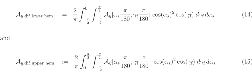
3.2.5 Treatment of diffuse irradiation
It is well known that the diffuse irradiation is very significant for the solar gains and that the angular dependence has to be considered for the calculation of the solar gains caused by diffuse irradiation [16]. In [16] and [17], the diffuse sky is divided into 145 discrete sky patches according to [33] and the ground is divided into 5 different rings with constant radiance. This procedure leads to very accurate modelling of the solar gains. This procedure could also be implemented in building simulation programs.
A simpler approach is to divide the diffuse irradiation into two components, one coming from the upper half of the hemisphere (in most cases above the horizon), the other being reflected from the ground (the lower half of the hemisphere). It is shown in section 5, for the case of venetian blinds, that it is necessary to treat these two components of the diffuse irradiation seperately, rather than assuming isotropic diffuse irradiation. This statement can also be proven heuristically for the case of an external venetian blind with matt silver slats without glazing: from the formulae given in [17], the solar transmittance for the upper half of the hemisphere can be deduced to be:
Ay,dif upper hem. ≈ b0Ay[0] + 2
6
X
k= 1
bkAy[15k] (11)
b0 = 0.1304 b4 = 0.0653
b1 = 0.1261 b5 = 0.0338
b2 = 0.1130 b6 = 0.0043
b3 = 0.0923
analogously:
Ay,dif lower hem. ≈ b0Ay[0] + 2
6
X
k= 1
bkAy[−15k] (12)
[image:13.612.43.485.472.607.2]In figure 1, the solar transmittance values for the upper and the lower halves of the hemisphere are shown for different tilt angles of the slats together with the total diffuse-hemispherical solar transmittance. It can be seen that the values for the upper half of the hemisphere are significantly lower than the values for the lower half of the hemisphere and the total values when the slats are tilted more than 10◦ against a horizontal plane.
Figure 1should be inserted here.
General rules for the calculation of diffuse properties
In general, the diffuse-hemispherical properties of facade systems Ay,dif can be calculated in the co-ordinate system [αs,γf] with equation (16) given in [17]:
Ay,dif := 1 π Z π 2 −π 2 Z π 2 −π 2
Ay[αs π 180, γf
π
180] cos(αs)
2cos(γ
f)dγfdαs (13)
whereαs andγf are expressed in degrees. Therefore
Ay,dif lower hem. := 2
π Z 0 −π 2 Z π 2 −π 2
Ay[αs π 180, γf
π
180[ cos(αs)
2cos(γ
f)dγfdαs (14)
and
Ay,dif upper hem. := 2
π Z π 2 0 Z π 2 −π 2
Ay[αs π 180, γf
π
180] cos(αs)
2cos(γ
f)dγfdαs (15)
3.2.6 Treatment of variable internal and external heat transfer coefficients
the external heat transfer coefficienthe. This leads to more effective transfer of the absorbed
energyαe,tot to the outside and therefore results in a lower g-value.
This effect is taken into account in the new black box model since the values for the solar absorptances αinner layer and αouter layer in the virtual layers are fixed and since the building
simulation program calculatesRe and Ri for every time-step according to the meteorological
input data for the location under examination.
3.2.7 Treatment of thermal mass
Two aspects of the thermal mass have to be taken into account in the black-box model:
• The total thermal mass
• The distribution of the thermal mass between the two virtual layers.
To assess the effect, the following cases have been compared:
• equal distribution of the typical thermal mass of a double-glazed unit (6mmglass panes) between the two virtual layers in the black-box model.
• 96 % of the total mass of case 1 concentrated in the outer virtual layer.
• 96 % of the total mass of case 1 concentrated in the inner virtual layer.
3.2.8 Treatment of back reflectance from the room
Since the black-box model uses effective absorptance values for each virtual layer, there is no change necessary in the building simulation programs for the internal treatment of back reflectance from the room. For the case of ESP-r, this means that the reflections from the room are correctly taken into account according to the descriptions in [30].
3.3 Examples
The angle-dependent properties of facades are the starting point for the calculation of the facade properties which are used as input for the black-box model (see section 3.2.1). The angle-dependent properties of facades can be either measured or calculated. For facades with venetian blinds, they can be calculated with the equations given in [17].
3.3.1 Examples: External blinds
As an example for external blinds,a venetian blind with convex matt silver slats is used. The near-normal-hemispherical solar reflectance of the surfaces of the slats is ρe,n-h = 0.51.
The near-normal-diffuse solar reflectance of the surfaces of the slats is ρe,n-dif = 0.47. For
the definition of the surface properties of the slats and the conditions for the reflectance measurements, see the European Standard EN14500 [10], to which the first author of this paper has contributed. The slats have additional small curved rims at the edges of the slats in order to increase their mechanical stability. Therefore the thickness of the slats is not negligible. This venetian blind (with small variations in the type of the matt silver colour of the slats) is the most common venetian blind in Germany, Switzerland and Austria. It has also been used for the assessments in [11]. In this example, the venetian blind has been combined with low-e glazing with ggzg = 0.58, τe,gzg = 0.51 and τv,gzg = 0.75. The angle-dependent
g-value and solar transmittanceτe of this facade are shown in figures 2 and 3. They have been
been calculated for the special case of unknown reflectance. The results are shown in figure 4. From the total absorptance, the solar absorptances in the two virtual layers have been calculated for the boundary conditions ofRe = (23W/(m2K))−1 , Ri = (8W/(m2K))−1 and
a U-value for the centre of glazing of 1.2 W/(m2K). α
inner layer and αouter layer for the two
virtual layers are shown in figures 5 and 6.
Figures 2 - 6 should be inserted here.
3.3.2 Examples: Internal blinds
The characterisation of facades with internal blinds has been discussed extensively in section 2.5.1. of [17] and in [18]. In this section, an internal Genius blind (for details see [18]) in combination with solar-control glazing withggzg[0◦] = 0.31 is used as an example. The same
combination has also been used in [18] and [11] as an example. Equations (21)-(24) from [17] were used for the calculation of the facade properties. The validation of these formulae is documented in table 4 and table 5 in [17]. Theg-valuegtot and the solar transmittanceτe,tot
are shown in figures 7 and 8.
In addition to the formulae given in [17], a new formula for the calculation of the solar reflectance ρe,tot was used:
ρe,tot[αs, γf, βk] =ρe,gzg[αin[αs, γf]]
+ τe,gzg[αin[αs, γf]] τx⋆
,dif,gzg
ρx⋆,bld[αp[αs, γf], βk]
1−ρx⋆
,dif,bld[βk] ρ′x⋆
,dif,gzg
(16)
aU-value of the centre of glazing of the facade of 1.1W/(m2K). αinner layerandαouter layerfor
the two virtual layers are shown in figure 10 and 11.
Figures 7 - 11 should be inserted here.
4
Implementation of the black-box model in ESP-r
4.1 Description of the implementation
The implementation is described in detail in [12].
4.2 Validation of the implementation
The correct implementation in ESP-r has been checked with a simple case that can be calcu-lated correctly also with the existing models in ESP-r [11]. For this purpose, a double-glazed unit(DGU) with a low-e coating on the outer surface of the inner pane was chosen. Glazing properties: ggzg = 0.58,τv,gzg = 0.75 and U-value = 1.0 W/(m2K). The results for the new
5
Assessment of the impact of the new model implemented in
ESP-r
In [17] it was shown that the solar gains through facades can be incorrect when the wrong angular dependence of the g-value is used. In [17], the author specifically assessed the difference between the assumption of properties with profile angle symmetry and rotationally symmetric properties. However, the effect on the results of building simulations were not assessed in [17]. This has now been done using the new black-box model implemented in ESP-r. The details are given in [11]. In [11], the operative temperature, the heating loads and the cooling loads of an office-room were analysed for the two different cases of angular dependence. The different angular symmetries for gtot are illustrated in detail in figure 12 of [17]. In [11] these effects
• For a fully glazed, south-facing facade in Freiburg, Germany with an external venetian blind with matt-silver slats, it was found that the wrong assumption of rotationally symmetric angular dependence leads to an underestimation of the total summer cooling load by 47 % in the case of a mechanically cooled building. The underes-timations of the total cooling load for the same building at the locations Milan and Stockholm are−55 % and−99 % respectively [11].
• For the same cases (but without a cooling system and with a west-facing instead of a south-facing facade), the assumption of the wrong rotationally symmetric properties leads to an underestimation of the average temperature by more than 2.5K and an underestimation of the maximum temperature by up to 5.2K[11].
• The heating energy demand is generally overestimated when the incorrect rotationally symmetric angular dependence is used. The relative overestimation of the heating de-mand for Freiburg, Milan and Stockholm is 17 %, 23 % and 20 % respectively [11].
These results highlight the improvements that can be achieved with the new interface for ESP-r. The application of the new black-box model is by no means limited to venetian blinds. There are many other types of complex glazing on the market which can now be modelled accurately in ESP-r. The roof glazing of the German Museum ´Haus der Geschichte´ (which contains metallic light-redirecting structures in order to transmit only the diffuse irradiation from the northern part of the sky) can be considered as an example for this type. For other examples see section 3.1.
6
Conclusion
• Measure gtot, τe,tot and preferably also ρe,tot for different directions of the incident ra-diation. If possible/applicable, the number of necessary measurements can be reduced when the data points can be interpolated with a sufficiently accurate physical model.
• Create an input file with these data for ESP-r.
• Run the building simulations.
The method has been implemented in ESP-r and the implementation has been validated. It should be easy to implement the method in other detailed simulation programs such as [9], [8], [31] or [32]. It was shown that there are practically relevant cases in which the new method can help to significantly increase the accuracy of determining the heating and cooling loads and the room temperatures. It was shown that the error of conventional simulation techniques can be quite large (55 % underestimation of the cooling load in Milan is possible when the wrong angular dependence is used).
7
Acknowledgements
References
[1] O. Aschehoug, S. Aydinli, J. Christoffersen, G. Courret, I. Edmonds, R. Jakobiak, M. Kischkoweit-Lopin, M. Klinger, E. Lee, L. Michel, J.-L. Scartezzini, S. Selkowitz, (ed.): Daylight in Buildings, IEA SHC Task 21/ECBCS Annex 29. LBNL Report Number:
LBNL-47493. http://gaia.lbl.gov/iea21/
[2] K. Bl¨umel, E. Hollan, A. Jahn, M. K¨ahler, R. Peter,Entwicklung von Testreferenzjahren (TRY) f¨ur die Klimaregionen der Bundesrepublik Deutschland. Scientific report of the Institute for Geophysical Sciences Technical University Berlin. BMFT-FB-T- 86-051, July 1986.
[3] C. B¨uhler,Mikrostrukturen zur Steuerung von Tageslichtstr¨omen, Inaugural-Dissertation zur Erlangung des Doktorgrades der Fakult¨at f¨ur Mathematik und Physik der Albert-Ludwigs-Universit¨at Freiburg, (PHD-Thesis), May 2003.
[4] J. Clarke, Energy Simulation in Buiding Design, second ed., Butterworth-Heinemann, 2001.
[5] A. Dama, Angular dependency of optical properties and energy performances of glazing and solar shading devices for windows and facades, Politecnico di Milano, Dipartimento
di Energetica, Dottorato di Ricerca in Energetica XVI ciclo (this PHD-thesis has been prepared in co-operation with Fraunhofer ISE, Freiburg Germany), Milan, Italy, Anno Accademico 2003-2004.
[6] J. A. Duffie, W. A. Beckman,Solar Engineering of Thermal ProcessesWiley-Interscience Publication, 1991.
[7] DIN EN 410Bestimmung der lichttechnischen und strahlungsphysikalischen Kenngr¨oßen von Verglasungen. Glass in Building - Determination of luminous and solar
[8] DOE-2 is a widely used and accepted building energy analysis program that can predict the energy use and cost for all types of buildings, http://www.doe2.com/.
[9] EnergyPlus, U.S. Department of Energy, EnergyPlus Energy Simulation Software, http://apps1.eere.energy.gov/buildings/energyplus/
[10] EN 14500Blinds and shutters - Thermal and visual comfort - Test and calculation meth-ods, European Standard, May 2008.
[11] F. Frontini, S. Herkel, T. E. Kuhn,Evaluation of a new method for solar control calcula-tion in the ESP-r building simulacalcula-tion program, submitted for publicacalcula-tion to Energy and
Buildings, 2009.
[12] F. Frontini, S. Herkel, T. E. Kuhn, P. Strachan, G. Kokogiannakis,Implementation of a new bi-directional solar modelling method for complex facades within the ESP-r building
simulation program and its application, conference paper IBPSA Building Simulation
2009, University of Strathclyde, Glasgow, Scotland, 27th - 30th July 2009.
[13] ISO 9050: Glass in Building - Determination of light transmittance, solar direct trans-mittance, total solar energy transtrans-mittance, ultraviolet transmittance and realated glazing
factors, International Organisation for Standardisation, Geneve, Switzerland, 1990.
[14] ISO 15099Thermal performance of windows, doors and shading devices - Detailed calcu-lations, International Organisation for Standardisation, Geneve, Switzerland, November
2003.
[15] J. Karlsson, A. Roos,Modelling the angular behaviour of the total solar energy transmit-tance of windows, Solar Energy, 69, 4 (2000).
[16] T. E. Kuhn, C. B¨uhler, W. J. Platzer Evaluation of overheating protection with sun-shading systems, Solar Energy Vol.69 (Suppl.) Nos. 1-6, pp. 59-74, 2000.
sim-ulation programs, Energy and Buildings, Vol 38, Issue 6, pp. 648-660, June 2006.
http://dx.doi.org/10.1016/j.enbuild.2005.10.002
[18] T. E. Kuhn, Solar control: Comparison of two new systems with the state of the art on the basis of a new general evaluation method for facades with venetian blinds or other
solar control systems, Energy and Buildings, Vol 38, Issue 6, pp. 661-672, June 2006.
http://dx.doi.org/10.1016/j.enbuild.2005.10.001.
[19] T. E. Kuhn, Sonnenschutz: Eine generelle Bewertungsmethode - auch f¨ur zwischen-liegende Systeme - und zwei neue Beh¨ange, Bauphysik, Vol 29 (2007), Heft 1, pp. 63-71,
2007. http://dx.doi.org/10.1002/bapi.200710012
[20] OPTICADOptical Analysis Program, Opticad Corporation, 511 Juniper Drive, Santa Fe (NM), 87501 USA.
[21] R. Perez, P. Ineichen, R. Seals, J. Michalsky, R. Stewart,Modeling of daylight availability and irradiance components from direct and global irradiance, Solar Energy 44 (5) (1990)
271-289.
[22] R. Perez, R. Seals, J. Michalsky,All-weather model for sky luminance distribution - pre-liminary configuration and validation, Solar Energy 50 (3) (1993) 235-245.
[23] J. Pfafferott,Enhancing the Design and Operation of Passive Cooling Concepts. Fraun-hofer IRB Verlag, Stuttgart, 2004.
[24] W. J. Platzer, Energetische Bewertung von Transparenter W¨armed¨ammung Fraunhofer ISE Study TOS4-WJP-9705-E01, June 1997.
[25] C. Reinhart, O. Walkenhorst, Dynamic RADIANCE-based Daylight Simulations for a full-scale Test Office with outer Venetian Blinds, Energy and Buildings 32 (2000)
167-187.
[27] J.L.J. Rosenfeld, Proc. of the 8th International Meeting on Transparent Insulation Material, Freiburg, Germany, 1996. It is difficult to get the paper, therefore it has been put with the permission of the author on the Fraunhofer ISE web-site: http://www.ise.fraunhofer.de/downloads/pdf-files/paper/paper-rosenfeld
[28] M. Santamouris (Editor) and Nicol F., Roaf S., Akbari H., Voss K., Kuhn T. E., Nitz P., Herkel S., Wall M., Hellstr¨om B., Kolokotroni M., Pfafferott J., Walker-Hertkorn S., Sanner B. and Erell E.,Advances in passive cooling, Earthscan, August 2007, 284 pages, ISBN: 9781844072637
[29] Simpson, J. R., McPherson, E. G.,The effects of roof albedo modification on cooling loads of scale model residence in Tucson, Arizona, Energy and Buildings, 25 (2), pages 127-137,
1997
[30] P. Strachan,Addition of Blind/Shutter Control to Transparent Multi-Layer Constructions and Other Improvements to the Solar Routines of ESPsim, ESRU Occasional Paper,
avail-able online as http://www.esru.strath.ac.uk/Documents/90/strachan solar mods.pdf
[31] TRNSYSThe Transient Energy System Simulation Tool, http://www.trnsys.com/
[32] TAS Thermal Analysis Software, http://www.harvardthermal.com/
[33] P. Tregenza,Subdivision of the sky hemisphere for luminance measurements, Light. Res. Technol. 19 (1987) 13-14.
[34] Wienold, J., Christoffersen, J.: Evaluation methods and development of a new glare pro-tection model for daylight environments with the use of CCD cameras, Energy and
List of Figures
1 Diffuse transmittance for an external venetian blind with convex (conventionally shaped) slats without glazing. The top surface of the slats is matt silver (ρe,tot=
0.59), the bottom is light grey (ρe,tot = 0.58). . . 25
2 g-value for an external, matt silver venetian blind with convex (conventionally shaped) slats in combination with glazing withggzg= 0.58. The line graphs on
the right hand side are valid forγf = 0 . . . 25
3 Solar transmittance τe for an external, matt silver venetian blind with convex
(conventionally shaped) slats in combination with a glazing with ggzg = 0.58.
The line graphs on the right hand side are valid forγf= 0. . . 26
4 Angle-dependent total solar absorptance αe,tot in the facade for an external,
matt silver venetian blind with convex (conventionally shaped) slats in combi-nation with glazing withggzg = 0.58. αe,tot has been calculated for the special
case of unknown reflectance ρe,tot. The line graphs on the right hand side are
valid forγf= 0. . . 26
5 Angle-dependent solar absorptance αinner layer in the facade for an external,
matt silver venetian blind with convex (conventionally shaped) slats in com-bination with glazing with ggzg = 0.58. αinner layer has been calculated for the
special case of unknown reflectance ρe,tot. The line graphs on the right hand
side are valid for γf= 0. . . 27
6 Angle-dependent solar absorptance αouter layer in the facade for an external,
matt silver venetian blind with convex (conventionally shaped) slats in com-bination with glazing withggzg = 0.58. αouter layer has been calculated for the
special case of unknown reflectance ρe,tot. The line graphs on the right hand
7 g-value for an internal venetian blind with Genius slats in combination with glazing with ggzg = 0.31. The line graphs on the right hand side are valid for
γf = 0. . . 28
8 Solar transmittanceτe for an internal venetian blind with Genius slats in
com-bination with glazing with ggzg = 0.31. The line graphs on the right hand side
are valid for γf= 0. . . 28
9 Angle-dependent total solar absorptance αe,tot in the facade for an internal
venetian blind with Genius slats in combination with glazing with ggzg = 0.31.
αe,tot has been calculated for the case of known reflectance ρe,tot. The line
graphs on the right hand side are valid forγf= 0. . . 29
10 Angle-dependent solar absorptanceαinner layerin the facade for an internal
vene-tian blind with Genius slats in combination with glazing with ggzg = 0.31.
αinner layer has been calculated for the case of known reflectanceρe,tot. The line
graphs on the right hand side are valid forγf= 0. . . 29
11 Angle-dependent solar absorptanceαouter layerin the facade for an internal
vene-tian blind with Genius slats in combination with glazing with ggzg = 0.31.
αouter layer has been calculated for the case of known reflectanceρe,tot. The line
0
10
20 30
40 50
60 70
tilt angle of the slats °
0
0.1
0.2
0.3
0.4
0.5
Tau_dif
Diffuse Transmittance for silver painted slats
Total diffuse transmittance
for lower hemisphere only
for upper hemisphere only
Figure 1: Diffuse transmittance for an external venetian blind with convex (conventionally shaped) slats without glazing. The top surface of the slats is matt silver (ρe,tot = 0.59), the
bottom is light grey (ρe,tot = 0.58).
75 50 25 0 25 50 75
azimuth° 75 50 25 0 25 50 75
alt.°
g_tot. Tilt angle of slats: 45 °
0.5 0 g
75 50 25 0 25 50 75
solar altitude° 0 0.1 0.2 0.3 0.4 0.5 g_tot
Ext. venetian blindsilver slats
with DGU
72° slat tilt angle 45° slat tilt angle 5° slat tilt angle
Figure 2: g-value for an external, matt silver venetian blind with convex (conventionally shaped) slats in combination with glazing withggzg= 0.58. The line graphs on the right hand
75 50 25 0 25 50 75
azimuth° 75 50 25 0 25 50 75
alt.°
Te_tot. Tilt angle of slats: 45 °
0.4 0 Te
75 50 25 0 25 50 75
solar altitude°
0 0.1 0.2 0.3 0.4 Te_tot
Ext. venetian blindsilver slats
with DGU
72° slat tilt angle 45° slat tilt angle 5° slat tilt angle
Figure 3: Solar transmittance τe for an external, matt silver venetian blind with convex
(conventionally shaped) slats in combination with a glazing withggzg = 0.58. The line graphs
on the right hand side are valid forγf= 0.
75 50 25 0 25 50 75
azimuth° 75 50 25 0 25 50 75
alt.°
a_tot. Tilt angle of slats: 45 °
0.5 0.3
75 50 25 0 25 50 75
solar altitude° 0.3 0.35 0.4 0.45 0.5 a_tot
Ext. venetian blindsilver slats
with DGU
72° slat tilt angle 45° slat tilt angle 5° slat tilt angle
Figure 4: Angle-dependent total solar absorptance αe,tot in the facade for an external, matt
silver venetian blind with convex (conventionally shaped) slats in combination with glazing withggzg = 0.58. αe,tot has been calculated for the special case of unknown reflectance ρe,tot.
75 50 25 0 25 50 75
azimuth° 75 50 25 0 25 50 75
alt.°
a_inner_layer Tilt angle of slats: 45 °
0.1 0
75 50 25 0 25 50 75
solar altitude° 0 0.02 0.04 0.06 0.08 0.1 a_inner
Ext. venetian blindsilver slats
with DGU
72° slat tilt angle 45° slat tilt angle 5° slat tilt angle
Figure 5: Angle-dependent solar absorptance αinner layer in the facade for an external, matt
silver venetian blind with convex (conventionally shaped) slats in combination with glazing
with ggzg = 0.58. αinner layer has been calculated for the special case of unknown reflectance
ρe,tot. The line graphs on the right hand side are valid for γf= 0.
75 50 25 0 25 50 75
azimuth° 75 50 25 0 25 50 75
alt.°
a_outer_layer Tilt angle of slats: 45°
0.5 0.2
75 50 25 0 25 50 75
solar altitude° 0.2 0.25 0.3 0.35 0.4 0.45 0.5 a_outer
Ext. venetian blindsilver slats
with DGU
72° slat tilt angle 45° slat tilt angle 5° slat tilt angle
Figure 6: Angle-dependent solar absorptance αouter layer in the facade for an external, matt
silver venetian blind with convex (conventionally shaped) slats in combination with glazing
with ggzg = 0.58. αouter layer has been calculated for the special case of unknown reflectance
75 50 25 0 25 50 75
azimuth° 75 50 25 0 25 50 75
alt.°
g_tot. Tilt angle of slats: 45 °
0.2 0
75 50 25 0 25 50 75
solar altitude° 0 0.05 0.1 0.15 0.2 0.25 g_tot Genius Slats
75° slat tilt angle 45° slat tilt angle 5° slat tilt angle
Figure 7: g-value for an internal venetian blind with Genius slats in combination with glazing withggzg= 0.31. The line graphs on the right hand side are valid for γf = 0.
75 50 25 0 25 50 75
azimuth° 75 50 25 0 25 50 75
alt.°
Te_tot. Tilt angle of slats: 45 °
0.2 0
75 50 25 0 25 50 75
solar altitude°
0 0.05 0.1 0.15 0.2 Te_tot Genius Slats
75° slat tilt angle 45° slat tilt angle 5° slat tilt angle
Figure 8: Solar transmittanceτefor an internal venetian blind with Genius slats in combination
!75 !50 !25 0 25 50 75
azimuth"° # !75 ! 50 !25 0 25 50 75
alt."° #
a_tot. Tilt angle of slats: 45 °
0.7 0.5
!75 !50 !25 0 25 50 75
solar altitude"° # 0.58 0.6 0.62 0.64 0.66 0.68 0.7 a_tot Genius Slats
75° slat tilt angle 45° slat tilt angle 5° slat tilt angle
Figure 9: Angle-dependent total solar absorptanceαe,totin the facade for an internal venetian
blind with Genius slats in combination with glazing withggzg= 0.31. αe,tothas been calculated
for the case of known reflectanceρe,tot. The line graphs on the right hand side are valid for
γf= 0.
$75 $50 $25 0 25 50 75
azimuth%° & $75 $50 $25 0 25 50 75
alt.%° &
a_inner_layer Tilt angle of slats: 45 °
0.2 0
$75 $50 $25 0 25 50 75
solar altitude%° & 0 0.05 0.1 0.15 0.2 a_inner Genius Slats
75° slat tilt angle 45° slat tilt angle 5° slat tilt angle
Figure 10: Angle-dependent solar absorptanceαinner layerin the facade for an internal venetian
blind with Genius slats in combination with glazing with ggzg = 0.31. αinner layer has been
calculated for the case of known reflectanceρe,tot. The line graphs on the right hand side are
'75 '50 '25 0 25 50 75
azimuth(° ) '75
'50 '25
0 25 50 75
alt.(° )
a_outer_layer Tilt angle of slats: 45°
0.6 0.5
'75 '50 '25 0 25 50 75
solar altitude(° )
0.5 0.51 0.52 0.53 0.54 0.55 0.56
a_outer
Genius Slats
75° slat tilt angle 45° slat tilt angle 5° slat tilt angle
Figure 11: Angle-dependent solar absorptanceαouter layerin the facade for an internal venetian
blind with Genius slats in combination with glazing with ggzg = 0.31. αouter layer has been
calculated for the case of known reflectanceρe,tot. The line graphs on the right hand side are