BEAVER MICRO-ROVER DEVELOPMENT FOR THE NORTHERN
LIGHT MARS LANDER
Mark A. Post* (a), Brendan M. Quine (b), Regina Lee (c)
(a) Doctoral Candidate, Department of Space Engineering, York University, Toronto ON, M3J 1P3 [email protected], (416) 736-2100 ext.77885
(b) Associate Professor, Department of Space Engineering, York University, Toronto ON, M3J 1P3 [email protected] , (416) 736-2100 ext.33483
(c) Assistant Professor, Department of Space Engineering, York University, Toronto ON, M3J 1P3 [email protected]
,
(416) 736-2100 ext.22095Abstract
The increasing number of successful robotic systems in place on earth and in space, and the miniaturization offered by modern technology, have enabled new kinds of low-cost planetary science missions. Scientific tasks on other planets can now be performed with small, intelligent, and self-managing robots that can be transported and deployed more easily and in greater numbers than large, complex robots. The Northern Light mission is a Canadian initiative to send a small lander carrying a micro-rover (μrover) known as the Beaver to Mars to study the Martian surface [1]. The Beaver is a solar-powered, autonomous ground roving vehicle of 6kg mass designed to perform simple mission planning and execution tasks autonomously and gather scientific data from modular payloads. It makes use of a modular system architecture, communicates with the lander and potentially other rovers using radio mesh networking and uses an efficient ARM-based onboard computer running embedded Linux and a suite of integrated sensors for navigation and planning [2]. A goal-based probabilistic mission planning and execution system are under development using Bayesian methods [3] for performing navigation, remote sensing or other simple tasks [4][5]. Distributed learning will allow rovers to share contextual data from their experiences in real time. A fully-functional Beaver prototype has been built as testbed for compact rover technologies and designs, and is intended to demonstrate the feasibility of using commercial off-the-shelf (COTS) components and innovative autonomy and control techniques in low-cost planetary science missions of the future.
Introduction
There have been many different types of autonomous and semi-autonomous planetary rovers developed for exploration. The successful Mars Exploration Rovers developed by NASA and JPL, Spirit and Opportunity, and the larger Mars Science Laboratory, Curiosity, represent the current extreme of size and complexity, and require considerable time and cost to build, transport, and operate. To minimize the mass that must be moved from one gravity field to another, Microrovers (<~10kg) and Nanorovers (<~10g) have emerged as a new paradigm for efficient and flexible planetary exploration [6]. Using a group of small rovers may also allow wider areas of survey and higher mission reliability. In the interest of creating lighter, simpler, more efficient, and more robust planetary robots, a variety of innovative concepts have been developed [7]. Recently, the rapid development of low-cost microcontrollers and highly-integrated logic devices for the mobile device market has made it possible to build modular, general purpose robotic hardware for a fraction of the cost and complexity needed even two decades ago. Autonomous ground vehicles with a long mission lifetime also need robust decision-making systems so that they can adapt to unknowns like mechanical wear, system failures, and changes in environmental conditions. It is desirable for the rover itself to be able to deal with uncertainties probabilistically and adapt its responses appropriately [3].
Beaver rover, which will leave the lander and perform geological surveying and imaging of the Martian surface and subsurface. The design of the Beaver was driven by several practical requirements [2], one of which was that the hardware be fabricated in-house. The chassis can be fabricated with common shop tools and commercially-available extruded aluminum. The electronic components can be hand soldered , inspected, and tested as needed for flight hardware, and large packages were used for better manual access, thermal dissipation and mechanical vibration tolerance. Components using ball-grid array or other no-lead packages were avoided for these reasons. Reliability is also a critical aspect for any system to be used remotely in space. Wherever possible, common and time-tested components were chosen to both increase reliability and ensure parts would continue to be available for future use. Data redundancy is used for the on-board computer system, and modules can be reprogrammed remotely if needed. The Beaver was also designed to be modular and flexible, so that a variety of payloads could be attached, and so that the Beaver would be useful both as a research platform and terrestrial rover, as well as space-qualifiable hardware. Two early prototypes of the Beaver have already been built and tested in the laboratory and outdoors at the Algonquin Radio Observatory, and a fully functional prototype is currently under construction at York University. Payloads under development include a micro-manipulator, a rock abrasion tool, and a ground-penetrating radar (GPR) unit for subsurface imaging.
Mechanical Design
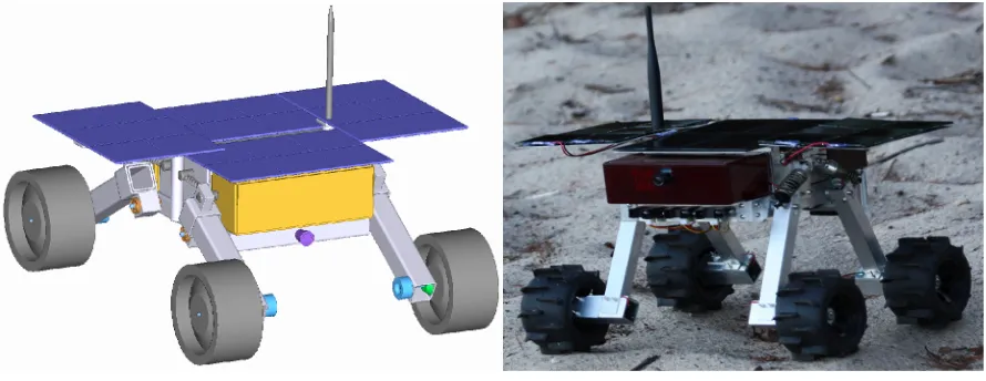
[image:2.612.84.529.393.565.2]The micro-rover chassis was designed to be simple and compact with a minimum of moving parts for reliability. Figure 1 shows a rendering in of the Beaver design. The electronics are housed in a 100mm x 150mm x 50mm box in the center of the chassis, and payloads are housed in up to 100mm x 150mm x 50mm boxes at the front and back. The base for these components is a square of tubular aluminum of horizontal size 300mmx150mm, through which wiring is run and sensors are placed for protection.
Figure 1: Beaver μRover CAD model and prototype in testing at ARO
springs when released from the lander. While stowed, the panels overlap facing up, so in the event of a deployment failure, some solar power can still be generated. The swing arm suspension uses spring-loaded sliding mounts adjacent to the chassis connection to extend longitudinally when released from the lander.
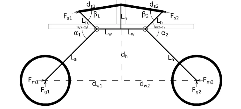
Limiting the rover model to the 2-D vertical plane, a simple diagram of the deployed suspension kinematics is shown in Figure 2. The dimensions are Lw = Lh = 50mm, La = 150mm, Lb = 50mm, with a
wheel diameter of 100mm. The suspension swing arms are supported by springs, and the position of each arm can be controlled by the force balance between the gravitational force Fg normal to the supporting
surface, the force Fm tangential to the supporting surface, and the force Fs on the suspension spring. The
equilibrium point of the suspension with respect to gravity is determined by the spring constant Ks and the
length ds compressed by a distance cs from its uncompressed point. Under the temporary assumption that
the surface is flat and each wheel supports one quarter of the rover's weight, the force Fg for the mass Mr
of the Beaver in gravity Gr and the motor force Fm for each arm to control the angles α and β are:
Fg=1
4MrGr=Kscscos(β) Lb
Lacos(α) , Fm=Kscscos(β) Lb
Lasin(α) (1)
[image:3.612.103.507.353.536.2]Testing of this suspension design has confirmed that ride height and horizontal stability can be controlled by varying motor torque during movement.
Figure 2: Planar model of Beaver suspension system
Electronic Design
functions have been modified to include essentials such as 3.3V and 5V power, serial and SPI communications, I2C buses, dedicated GPIO pins, board-to-board USB, and a camera interface.
The solar array is used to charge a three-cell stack of high-density Lithium-Ion batteries with a balanced charge method that ensures each cell is charged to its nominal voltage. The cells power the electronic and mechanical systems via switching DC-DC voltage regulators that step voltage down to the needed level. Stepping voltage up is avoided for efficiency reasons. Only the first Li-Ion cell is needed for for 3.3V electronics and below, the first and second are used for a 5V supply, and all three cells are used to provide close to 12V for drive motors and high-power payloads such as radar. All power regulators are heatsinked to the chassis to ensure sufficient heat dissipation to the exterior, and voltage and current levels for each regulator are monitored by the on-board computer.
The motherboard includes all the basic components necessary for the operation of the on-board computer including the Li-Ion battery charger, 3.3V and 1.8V switching power regulators, 64MB of SRAM, a NAND flash and SPI dataflash for non-volatile storage, and USB, Serial, and Ethernet ports for software development use, as well as voltage, current, and orientation sensors. Daughterboards can then be stacked on top to add functionality, such as motor controllers, sensor packages, and communications systems. A motherboard and daughterboards for drive motor control and payload/sensor interfacing have been designed and are undergoing functional and environmental testing.
[image:4.612.83.532.443.678.2]The Beaver uses a custom motor control system on a daughterboard that is small and efficient enough to meet space and power constraints, but flexible and robust enough in operation to perform under space conditions. Three Infineon high-current half-bridges, controlled from an AVR microcontroller, are used to drive each brushless motor. Integrated Hall sensors on each motor feed hardware timers on the microcontroller, which are used to time the switching of the motor coils by controlling the half-bridges with general-purpose IO pins [2]. Due to the use of general-purpose IO and timers for control, this drive system also has the benefit of being able to run brush DC motors and servos with only software changes, which is very useful for hardware testing on other platforms.
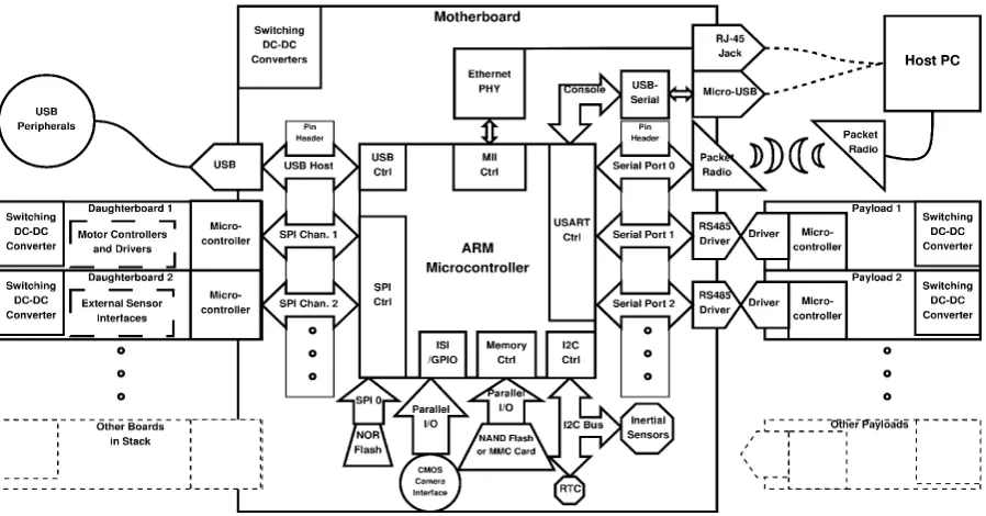
While the on-board computer stack is completely enclosed in the body of the rover, there is space for two payloads front and back under the solar array. Communications with external payloads is primarily via RS-485 differential serial bus, which can communicate reliably in full or half-duplex with up to 32 devices. Parallel and SPI interfaces are also available from the internal board stack. All external connections are via high voltage and ESD protected buffers to prevent damage to internal systems, and use robust D-sub connectors. Daughterboards and payloads typically use smaller, more purpose-built microcontroller hardware such as the Atmel AVR 8-bit architecture, which is easily in-system programmable using GNU C/C++ compilers and open-hardware SPI programmers. Communications with these subsystems is by serial, SPI, and parallel buses. FPGAs and CPLDs are not generally used as these devices use significantly more power than comparable microcontrollers, although some payloads requiring specialized high-speed processing may need them in the future. Communications between rovers and the lander or a ground station for development is by long-range 900MHz serial radio link using mesh networking modules such as the Digi XBee Pro. For a high-power planetary uplink, a dedicated UHF radio system is planned for development as an on-board computer daughterboard. A complete diagram of the electronic systems is shown in Figure 3.
Control and Autonomy
The software for the Beaver is programmed in C for efficiency and portability, as well as compatibility with the Linux environment used. The Gnu Compiler Collection (GCC) is used to facilitate cross-development for the ARM architecture, and peripheral drivers are already available or have been added in the Linux kernel. Programs for microcontrollers are generally stored in NAND flash memory and the Linux kernel and filesystem for the ARM architecture are stored on redundant NAND and NOR flash devices on the motherboard. NAND flash is the most common and provides large storage capacity, while NOR flash devices can store only a few megabytes but may be more resistant to radiation and corruption [8]. To mitigate the risks of software corruption, two redundant kernel and UBIFS filesystem images are used to boot the ARM Linux system, which can then reprogram the other system microcontrollers as required using SPI. The kernel also is modified to provide redundancy in SRAM using a triple-voting system to correct minor errors on the fly.
The Beaver μrovers use probabilistic methods for mission planning and distributed problem-solving, which means that the rovers and their environment they are aware of are modeled as a network of random variables. A Dynamic Bayesian Network is used to represent interrelated probabilities that are seeded from prior data, and which may change as actions are performed and information on success or failure is gathered. Bayesian Networks (BN) are well-suited for handling uncertainty in cause-effect relations, and represent dependence/independence relationships well provided that the network is constructed using valid relational assumptions. They are generally represented by a directed acyclic graph (DAG) which defines a factorization (links) of a joint probability distribution over several random variables (nodes). An algorithmic methodology for Bayesian inference and learning in robots known as Bayesian Robot Programming uses discrete random variables as sets of mutually exclusive logical propositions to carry out probabilistic reasoning using basic inference postulates [3]. Discrete variables X1...Xn are partitioned
into k subsets, with variables L1...Lk for each subset, and using conditional independence to simplify,
variables Ri is the conjunction of some Xj of these variables. Bayesian inference is carried out by
searching of the network for the highest concentrations of probability maxima by computing the distribution:
P
(
searched∣known)
=1Σ×unknown
∑
[
P(
L1)
×∏
i=2 kThe probability data used for the Bayesian network is stored and shared between Beaver μrovers in XML format, specifically the open XMLBIF format developed for portable storage of Bayesian inference data [9].
As the Bayesian network is used for planning and decision-making processes based on the system state, it is also necessary to filter the sensors used for state estimation. Filtering and correction of sensor data is performed by using Sigma Point Kalman Filtering strategies such as the unscented Kalman filter (UKF). As these filters are are also based on Bayesian statistics, the filter can adapt to changing operating conditions by updating the state and sensor noise covariance matrices based on the state residual after each filter iteration [10]. To allow efficient operation on embedded microcontrollers without floating-point hardware, a fixed-floating-point math implementation is used with the whole portion represented in the first half of each machine word and the fractional portion in the second half. A 32-bit word length is used on the ARM architecture and a 16-bit word on the AVR architecture. This approach is used for all
algorithms that would otherwise require floating-point math, including the UKF and Bayesian inference algorithms. This allows even an 8-bit microcontroller to perform filtering, which helps to offload computation from the ARM-based OBC motherboard.
Conclusions
The Beaver micro-rover is designed to be a flexible, efficient, inexpensive, and robust platform for research and planetary exploration. A simple chassis design and modular electronic system can be used in conjunction with probabilistic decision-making and control methods to perform basic planetary exploration and science tasks. By making use of COTS hardware and open software architectures, it is possible to develop and fabricate in significantly less time and cost than large rovers. Further improved and space-qualified versions of the Beaver will provide the Northern Light mission with mobility on the surface of Mars.
References
[1]. Quine, B., Lee, R., and Roberts, C. (2008). "Northern light - a Canadian Mars Lander Development Plan." In Conference Proceedings of CASI ASTRO 2008, Montreal, Canada.
[2]. Post, M.A., Lee, R., and Quine., B. “Modular Design for Space Engineering Research Platforms”. 8th International Conference on Informatics in Control, Automation and Robotics (ICINCO). Noordwijkerhout, Netherlands, July 29, 2011.
[3]. Lebeltel, O., Bessiere, P., Diard, J and Mazer, E., “Bayesian Robot Programming”. Autonomous Robots, vol.16, pp.49–79, 2004
[4]. Pedersen, L., et al. “Mission Planning and Target Tracking for Autonomous Instrument Placement”. IEEE Aerospace 2005. Big Sky, Montana, USA.
[5]. Fleder, M., Nesnas, I.A., Pivtoraiko, M., Kelly, A., Volpe, R. “Autonomous Rover Traverse and Precise Arm Placement on Remotely Designated Targets”. IEEE International Conference on Robotics and Automation (ICRA), 2011. May 2011.
[6]. Wilcox, B. “Nanorovers for Planetary Exploration”. Jet Propulsion Laboratory, California Institute Of Technology. 1996
[7]. Barlas, F. “Design of a Mars Rover Suspension Mechanism”. Master's Thesis, Izmir Institute of Technology, Izmir, Turkey. June, 2004
[8]. Farokh, I., Nguyen, D. “Radiation Tests of Highly Scaled High Density Commercial Nonvolatile Flash Memories”. Jet Propulsion Laboratory, California Institute of Technology, Pasadena, CA, 2008.
[9]. Cozman, F. G. “The Interchange Format for Bayesian Networks”. Web Site, August 1998. Available: http://www.cs.cmu.edu/~fgcozman/Research/InterchangeFormat/