Abstract: as domestic electrical energy consumption keeps increasing, consumers become more aware of energy usage and efficiency because of economic and environmental reasons. The energy meter described in this paper is aimed at household smart metering for better energy management. The meter system uses a single microcontroller to acquire mains voltage and current waveforms and calculate power parameters: RMS voltage and current, instant power, power factor and energy. These parameters are stored locally on memory card for long period standalone recording, or transmitted in real time using an IoT Long Range radio for instant readings or short period monitoring. Measurement data of electrical power usage of a typical family household and energy consumption is presented where domestic appliance patterns are identified over an operating period. These patterns enable the estimation of energy usage distribution among appliances.
Keywords : energy meter, energy monitoring, smart metering, arduino, LoRa, IoT.
I. INTRODUCTION
Worldwide electrical energy consumption has been increasing in the past and has a tendency of growing in the next years. The demand for living comfort with increasing use of electrical appliances and the simpler use of electricity against gas or other forms of energy has increased household electrical energy consumption. The advent of the electrical car will increase even more the domestic use of electrical energy. Measurement of energy consumption is a key issue and smart metering on the grid becomes increasingly important [1] for monitoring purposes where IoT plays a major role [2, 3]. It should be possible for the end user to access smart grid data for its own household monitoring purposes enabling better energy usage efficiency for economic reasons and also environmental ones. However, the solution from supplier side may not be the optimum or a flexible one [4] or simply not available in most cases.
There are many devices commercially available to measure and monitor household energy consumption. The most complex ones are connected to the electrical main panel to measure the whole household consumption while the simpler ones are connected directly to the appliance. However these solutions are usually still not expandable or flexible for specific purpose. Alternative solutions for energy measurement end up being proposed such as [5] and [6] to cover energy distribution quality and even enforcement.
This paper describes an alternative approach on energy
Revised Manuscript Received on September2, 2019.
Fernando Fortes, ADEETC, Instituto Superior de Engenharia de Lisboa and Instituto de Telecomunicações, Lisbon, Portugal. Email: [email protected]
Vítor Fialho, ADEETC, Instituto Superior de Engenharia de Lisboa and Centre of Technology and Systems, Lisbon, Portugal. Email: [email protected]
meter design suitable for household smart metering. The meter has an LCD panel for direct monitoring and can be controlled locally or remotely. It operates in two modes: standalone and remotely. Standalone mode records a long stream of data on local storage without the need of an all-time connected host to transmit the data into. It is then possible to evaluate the household energy usage profile over the recorded period and also identify an appliance operation without measuring it separately [7]. This enables a better energy management. Remote operation mode is achieved by transmitting data wirelessly to the host using a radio interface. Instant readings upon user request or short period monitoring are provided to have real time data of the entire household consumption profile.
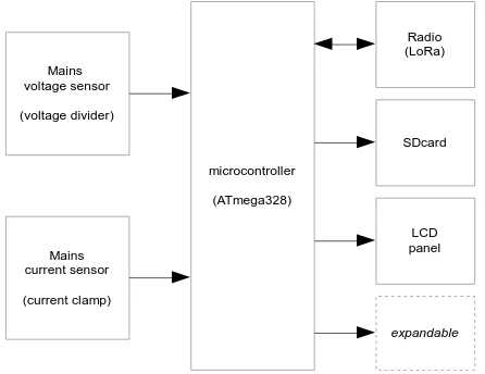
The energy measurement system is based on a single microcontroller to perform all the required measurement tasks with its building blocks presented in Fig. 1. The system uses the ATmega328p [8] microcontroller, very popular among Arduino [9] platform. Using a single microcontroller to realize all the functions required for energy metering and monitoring enables the realization of a low complexity and compact meter system. Voltage and current waveforms coming from the sensors are digitized to calculate RMS voltage and current, effective power and power factor and total energy. The resulting data is shown on the LCD panel for direct monitoring. Upon user request this data may also be transmitted to a host through the LoRa [10] wireless interface or stored locally on a memory card (SDcard) to provide monitoring of several days if needed. The system can be expanded with a few options but limited to the microcontroller processing power.
microcontroller
(ATmega328)
LCD panel SDcard Mains
voltage sensor
(voltage divider)
Mains current sensor
(current clamp)
[image:1.595.316.539.539.711.2]expandable Radio (LoRa)
Fig. 1.Energy meter system building blocks.
Smart Energy Meter For Iot Applications
Section 2 presents the energy meter and its design, describing the mains voltage and current sensors and their digitization process, calculation of RMS voltage and current, effective power, power factor and total energy. Section 3 presents the operation modes of the energy meter and experimental examples, including a long period complete household consumption while Section 4 shows the energy usage distribution among appliances and identifies the ones with the largest consumption. Conclusions and future work are presented in section 4.
II. ENERGY METER DESIGN
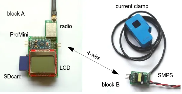
The energy meter system photo is shown in Fig. 1. It is split in two blocks A and B, connected with a 4-wire cable. Block A contains the ProMini microcontroller board, LCD panel for quick monitoring, radio board for wireless access and SD card slot for large data storage. These elements are assembled on a prototyping board. Block B contains a 3.3 V switching mode power supply (SMPS) and sensors (analog elements) assembled on the bottom of another prototyping board. A 4-pin connector on the microcontroller board is available for serial interface.
A. Microcontroler and analog to digital conversion The microcontroller used in the energy meter system is an 8-bit Atmega328p [9] embedded on an Arduino ProMini board. This board has the all required components for a minimalist microcontroller system and includes IO pins for analog and digital interface. There are a few versions of this board differing in voltage supply and consequently in clock frequency. Due to SD card and LCD voltage restrictions the used board version is powered with a 3.3V power supply. The 3.3 V supply limits the clock on the arduino board to 8MHz which degrades processing performance. However it is still enough for all the functions required in the energy meter and has the advantage of lower power consumption. It is also a challenge to optimize the complete system timing.
The ATmega328p has a single successive approximation ADC with 10–bit resolution and minimum conversion time of 13 µs. The ADC input is connected to one of the 6 analog channels (pin A0 to A5) using the internal multiplexer and this selection is made by software. In this system the voltage
waveform sensor is connected to pin A0 and current waveform sensor to pin A1. Since the microcontroller has a single ADC it firstly acquires the voltage waveform channel on pin A0 and secondly the current waveform channel on pin A1. Therefore voltage and current waveform samples are not synchronized and have a time difference of 13 µs. However considering a 50 Hz (20 ms period) mains frequency, the difference angle on the digital acquisition between voltage and current waveforms is 0.23°. This has a negligible impact on power factor calculation since cos(0.23°) ≈ 0.999992. Besides analog to digital conversion the microcontroller has also to perform the calculation of voltage and current RMS values as well as instant power. A sampling rate of 1 kHz or 20 samples per cycle at 50 Hz mains frequency was chosen which is adequate to measure the sinusoidal voltage and current waveforms of resistive load appliances in the household. It is also adequate to most of appliances with switching power supplies although some of those with poor harmonic filtering may not be correctly measured. However these are usually low power and have a minor impact on the whole power consumption.
B. Mains voltage and current sensors
The ADC in the microcontroller converts analog voltage in [0 Vsupply] range with Vsupply = 3.3V. Hence the mains voltage and current waveforms must be conditioned to voltage signals with amplitude Vsupply / 2 = 1.65 V and DC offset of 1.65 V to use the ADC full range.
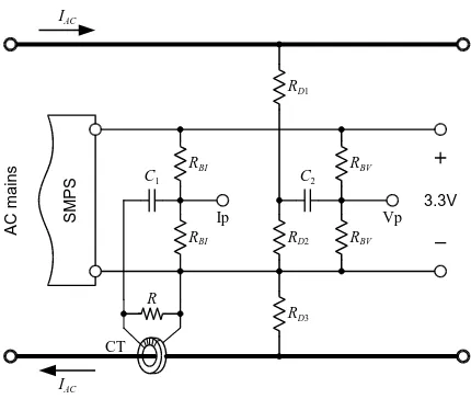
Fig. 3 shows the circuit which conditions AC mains voltage and current to the adequate ADC voltage range. Mains voltage sensor is a resistive divider RD1, RD2 and RD3 while resistors RBV bias the voltage signal with the appropriate 1.65 V offset. The voltage dividing factor or sensor sensitivity AV is given by
RBV RD D D
RBV RD V
R R A
2 2 1 3 1
2 2 1
1 1
block B block A
LCD radio
SDcard ProMini
current clamp
SMPS 4-w
[image:2.595.146.450.51.208.2]ire
Fig. 2.Energy meter system splitted into two blocks A and B. Block A contains the microcontroller, LCD panel, SD card slot and a radio for remote access Block B contains a 3.3 V switching mode power supply (SMPS) and the analog
A
C
m
ai
n
s
RBV
3.3V
Ip Vp
S
M
P
S
RD1
RD2
RD3 RBV
RBI
RBI
C1 C2
CT R
IAC
[image:3.595.61.276.53.235.2]IAC
Fig. 3.Mains voltage and current waveform conditioning circuit for ADC conversion. Voltage measurement is
made with a resistive divider while and current measurement is made with a current transformer clamp. With RD1 = RD3 = 1.2MΩ, RD2 = 33 kΩ and RBV = 33 kΩ the resulting dividing factor is 4.56 mV/V. Considering a maximum sinusoidal voltage amplitude on the ADC of 1.65 V the maximum mains input voltage amplitude is 361.6 V or 255.7 V RMS. Larger values will cause clipping distortion due to ADC out of range.
The mains current sensor uses a current transformer clamp CT with N turns, loaded with a resistor R while resistors RBI bias the ADC input with the adequate 1.65 V offset. The sensor sensitivity AI is ratio between voltage across R and mains current. Considering that resistors RBI have a much larger value than R the sensor sensitivity is approximately given by
R
N
AI 1 *
Unlike the fairly constant amplitude of the voltage waveform, current amplitude changes according power consumption. The current amplitude changes from low values up to a maximum value which depends on the household contract power. For this measurement system a 4.6 kVA or 20 A RMS under 230 V RMS was considered as a reference value. Using a current transformer clamp with a 2000 turns and R = 100 Ω results in a sensor sensitivity of 50 mV/A. Resistors RBI have 47 kΩ which are much larger than R as required. Considering a maximum sinusoidal voltage amplitude on the ADC of 1.65 V then the maximum mains input current amplitude is 33 A or 23.3 A RMS. A larger value will cause clipping distortion due to ADC out of range. The measurement of a larger current value requires lower R values to avoid clipping. However the measurement of low value currents will degrade.
C. Electrical parameters
Although the electrical parameter calculation is a straightforward process it is quite demanding for an 8-bit microcontroller operating at 8 MHz. The system is always sampling voltage and current at 1 kHz rate and makes the calculations between the sampling process. The mains voltage and current RMS values, effective power and power factor are calculated over one second period (1000 samples) for
averaging. All these quantities are calculated using floating point numbers. Energy is also calculated by integrating the effective power over time.
The process of electrical parameters calculation starts by reading the samples from the ADC for the voltage and current in the range [0 .. 1023]. DC offset is then digitally removed to obtain a digital word in the range [−511 .. 511] for the voltage VADC and current IADC. Finally the mains voltage Vn and current In sample values are calculated using the voltage and current sensor sensitivities AV and AI andcorresponding 511 digital value to 1.65 V analog value
511 65 . 1 *
V ADC n
A V
V
511 65 . 1 *
I ADC n
A I
I
The system takes 1000 samples to calculate RMS values of voltage and current and effective power over one second period with equations
1000
1 2
1000 1
n n
RMS V
V
1000
1 2
1000 1
n n
RMS I
I
1000
1 *
n
n n EF V I
P
Finally apparent power PAP and power factor PF are calculated with equations
PAPVRMS*IRMS
AP EF
P P
PF
These parameters are then converted to character string for direct viewing, recording and transmission. The format and number of characters was chosen according the expected values and is presented on Table I.
TABLE I. ELECTRICAL PARAMETERS STRING FORMAT
n char max unit
VRMS 3 999 V
IRMS 5 99.99 A
PEF 4 9999 W
PF 4 1.00
E 6 9999.9 kWh D. Radio interface
Modern wireless communications allow the choice of several possibilities for the radio interface when distance range, data transmission rate and power consumption are concerned. The chosen radio interface for this energy meter was a LoRa module from EBYTE [11] operating at 868 MHz with an UART interface. This module is used for long range communications and allows several data rates according communication distance. The minimum data rate of this module is 300 bit/s which cover the required 160 bit/s. It also has to the longest communication range.
III. ENERGY METER OPERATION RESULTS The energy meter is connected on the mains board and the several measurement options selected by user are described in the following subsections.
A. Direct monitoring
In this mode of operation the energy meter presents the electrical parameters on the LCD as illustrated in Fig. 4. The LCD photo was taken after a few days of monitoring. This mode is useful for energy reading and instant mains voltage, current, power and power factor monitoring.
energy
VRMS
PEF
IRMS
[image:4.595.105.232.331.390.2]PF
Fig. 4.Photograph of the energy meter LCD panel, monitoring after a few days operation.
B. Long period energy monitoring
The long period monitoring allows a finer evaluation of
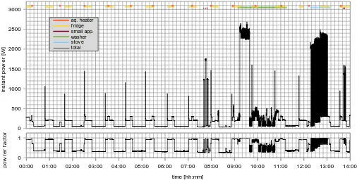
energy consumption and the identification of patterns. In this example the monitoring was made over a couple of days and generated a large amount of data. For an easier and clear interpretation of results a shorter monitoring period is presented. Fig. 5 illustrates a monitoring period between 00h00m and 14h00m of instant power and power factor. This period includes overnight, when the number of operating appliances is reduced and therefore easier to interpret the recorded values and identify a few patterns. It also includes a period with typical daytime operation.
The minimum registered power when no appliances are operating is close to 45 W – this value is quite large and has a low power factor and is due to the several appliances standby modes and always ON equipment.
Between 00h30m and 7h30m two main power consumers are identified with a unique pattern: a 100 W heat resistor with thermostat to maintain an aquarium temperature and a refrigerator. Both have a periodic operation close to one hour and the resulting instant power waveform is mainly the superposition of these power consumers. The rise of power factor towards 1.0 is also noticeable when these appliances are operating.
After 7h30m becomes more difficult to identify patterns. Hence power level, operation time and duration are all considered to find which appliances are operating. Between 7h30m and 8h00m two power consumers are identified and categorized as ‘small appliance’: a microwave oven with 1200 W and a toaster with 1600 W power consumption both with a few minutes operation time. After 8h30m the following appliances are in operation: washing machine between 9h10m and 11h15m; electric stove between 12h15m and 13h10m and a coffee machine between 13h40m and 13h50m also categorized as ‘small appliance’.
0 500 1000 1500 2000 2500 3000
aq. heater f ridge small app. washer stov e total
time [hh:mm]
in
s
ta
nt
p
o
w
e
r [
W
]
p
o
w
re
r f
ac
tor
00:00 01:00 02:00 03:00 04:00 05:00 06:00 07:00 08:00 09:00 10:00 11:00 12:00 13:00 14:00
0 1
Fig. 5.Results of instant power and power factor monitoring between 00h00m and 14h00m and ON time of different loads: aquarium heater (red), refrigerator (yellow), small appliance (brown)
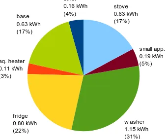
[image:4.595.46.552.483.746.2]IV. MEASUREMENT RESULTS DISCUSSION This power usage monitoring enables the total and individual appliance energy calculation. The energy is calculated by integrating instant power on a determined time period. However while total energy usage is a direct and accurate process, individual appliance energy usage is extracted from the whole and its accuracy depends on its correct identification. In the case of the aquarium heater and refrigerator the energy usage evaluation is direct due to their well-defined periodic pattern. More complex energy patterns and superposition of several patterns generate less accurate energy usage values but still enable a valuable estimate. The total energy consumption during this 14 hour monitoring period is 3.66 kWh and is distributed according the chart in Fig. 6 (values in kWh). The value of category ‘base’ was obtained by integrating the minimum 45 W power consumption over 14 hour period. The category ‘other’ was obtained by the difference of total energy and the sum of the other portions. The largest energy consumer with 31 % is the washing machine (1.15 kWh) and is mainly due to the water heating phase from 9h15m to 9h40m (25 minute duration). Another large power appliance is the electric stove with 2000 W used from 12h15m until 13h00m (45 minute duration). However, due to its pulsed operation according required temperature the energy usage is only 0.63 kWh. The small appliances also have a large rated operating power but use only 0.19 kWh because of their short operating time. An interesting conclusion is that appliances with periodic operation (refrigerator and aquarium heater) together with always ON equipment and others on standby mode (‘base’ category) account for more than 40 % energy usage.
other 0.16 kWh (4%) base
0.63 kWh (17%)
aq. heater 0.11 kWh (3%)
f ridge 0.80 kWh (22%)
w asher 1.15 kWh (31%)
[image:5.595.84.254.426.567.2]small app. 0.19 kWh (5%) stove 0.63 kWh (17%)
Fig. 6.Energy usage distribution among appliances. The data provided on the chart in Fig. 6 is extremely useful but is limited to a 14-hour period. A larger monitoring period will give more complete information on energy usage but while periodically operating appliances are readily identified the manual identification of new appliances becomes tedious or impossible without logging their operation. This may be mitigated by using several energy meters to monitor different parts of the household and remotely access them.
V. CONCLUSIONS
This paper presented a system to measure household energy consumption with the option to monitor and record power consumption with one second resolution. The monitored data can be remotely transmitted or stored locally on a memory card. The system is based on a single microcontroller to measure the voltage and current waveforms, parameter calculation and monitoring interface. The voltage and current
sensors are placed on the mains board to monitor the whole household.
The system measures the whole power consumption and individual appliance using pattern identification. This allows the identification of energy usage distribution among appliances and enables a better energy usage management. For example it allows concluding that periodic operating appliances together with always ON equipment account for more than 40 % energy usage.
Although this system was designed for energy metering and monitoring it can be expanded to include other sensors or interfaces. An example is a temperature and humidity sensor to help evaluate the energy needs for heating or cooling in air conditioning system. It can also generate a warning when the value of contract power is reached.
REFERENCES
1. D. Alahakoon and Xinghuo Yu, “Smart Electricity Meter Data Intelligence for Future Energy Systems: A Survey,” IEEE Trans. on Ind. Informatics, vol. 12, pp. 425-436, Feb. 2016.
2. R. Morello, C. Capua, G. Fulco, S. Mukhopadhyay, “A Smart Power Meter to Monitor Energy Flow in Smart Grids: The Role of Advanced Sensing and IoT in the Electric Grid of the Future,” IEEE Sensors J., vol. 17, pp. 7828-7837, Dec. 2017.
3. M. Rizzi, P. Ferrari, A. Flammini, E. Sisinni, “Evaluation of the IoT LoRaWAN Solution for Distributed Measurement Applications,” IEEE Trans. on Instr. and Meas., vol. 66, pp. 3340-3349, Dec. 2017. 4. E. Spanò, L. Niccolini, S. Pascoli, “Last-Meter Smart Grid Embedded in
an Internet-of-Things Platform,” IEEE Trans. on Smart Grid, vol. 6, pp. 468-476, Jan. 2015.
5. H. Das, L. Saikia, “GSM Enabled Smart Energy Meter and Automation of Home Appliances”, International Conference on Energy, Power and Environment: Towards Sustainable Growth (ICEPE 2015), June 2015 6. M. Prathik, K. Anitha, V. Anitha “Smart Energy Meter Surveillance Using
IoT”, International Conference on Power, Energy, Control and Transmission Systems (ICPECTS-2018), Feb. 2018.
7. Y. Farzambehboudi, O. Erdinç, A. Boynueğri, L. Ucun, M. Ali Öz, “Economic Impact Analysis of Load Shifting in a Smart Household”, International Conference on Smart Energy Systems and Technologies (SEST-2018), Sept. 2018
8. www.microchip.com/wwwproducts/en/ATmega328p 9. https://www.arduino.cc/
10. https://lora-alliance.org/
11. http://www.ebyte.com/en/index.aspx
AUTHORS PROFILE
Fernando Fortes, BsC, MsC, PhD. He received BsC from Instituto Superior de Engenharia de Lisboa in 1992, MsC and PhD in 2001 from Instituto Superior Técnico, Portugal. He is an assistant professor with 20 year experience currenty teaching at Instituto Superior de Engenharia de Lisboa, Portugal. His research interests include analog and digital electronics, RF electronics, RFIC design and characterization.