International Journal of Innovative Technology and Exploring Engineering (IJITEE) ISSN: 2278-3075, Volume-9 Issue-2, December 2019
Abstract: The use of electronic ballast and switching mode power supply in energy conservation has caused power quality problems and less reliable output voltage. Power factor correction (PFC) converters and output voltage are conventionally regulated using the PID controller to condense the current harmonics, increase the power factor and regulate the system output voltage. In general, their output is not very appropriate for non-linear systems. Because this approach is highly non-linear, the PID controller gain optimized in this paper using the grey wolf optimization algorithm to increase the power factor and boost the stability of the AC to DC process output voltage. The simulation studies to demonstrate the efficacy of the proposed grey wolf optimized PID controller is performed in MATLAB Simulink to achieving balanced performance and high power factor.
Keywords : Grey Wolf Algorithm, Power Factor Correction, PID controller, Voltage regulation.
I. INTRODUCTION
N
ow day‟s the numerous linear and nonlinear loads used in electrical power system i.e., the energy-efficient ballast, solid state motor system and personal computers are the nonlinear loads used in the power system. Because of nonlinear loads, the current shape is non-sinusoidal and it causes the problem in power system. Modern rectifiers and similar instruments take the non-sinusoidal current and the harmonics distort it. In general, the diode rectifier in the AC-DC conversion systems is used by a switched mode power supply. The input current of the AC system draws the non-sinusoidal current, i.e. fast pulsing current, due to the diode rectifier [1]. In the diode rectifier, the current peak value is always high to provide the same amount of power in the form of short pulses. Because of this effect, in the power system control system, wiring, circuit breakers and distribution equipment are under stress. As a consequence, harmonics are produced in the current; the supply system's power factor is reduced due to non-sinusoidal current and non-standard total harmonic level [2]. In order to reduce the stresses in the power system equipment and to improve theRevised Manuscript Received on December 22, 2019.
* Correspondence Author
*K.Premkumar, Dept. EEE, Rajalakshmi Engineering College, India. Email id: [email protected]
Prema Kandasamy, Dept. EEE, Thangavelu Engineering College, India. Email id: [email protected]
M.Vishnu Priya, Dept. ECE, Saveetha School Engineering, India. Email id: [email protected]
P.Palanikumar, Dept. EEE, Thangavelu Engineering College, India. Email id: [email protected]
S.B.Ron Carter, Dept. EEE, Rajalakshmi Engineering College, India. Email id: [email protected]
actual power flow from input to load side, the power factor correction circuit could be applied to the power system to enhance the input current shape and the power factor circuit would adjust the unit phase angle between the input supply system current and voltage [3-4].
Power factor correction is the most important field in the power electronic system and is the most powerful technique in the power electronics system. Power factor correction can be classified into two areas, one is passive power factor correction and second one is active power factor correction. Passive components are used in the passive power factor correction such as inductor and condenser. This will convert the non-sinusoidal current to the sinusoidal current, but this process does not regulate the output dc voltage at a constant level. The semiconductor device incorporates passive elements to adjust the input current shape and control the output voltage of the AC-DC.
Active power factor correction circuits usually use the boost, buck-boost DC-DC converter feature after the AC-DC rectifier circuit and increase the system's power factor [5-7]. Most power factor circuits use Buck or boost converter topology because they have a high power factor capability.
Usually, the power factor correction and output regulation of the single phase AC-DC system is built using a proportional integral derivative controller but it has some drawbacks such as obtaining the proportional integral derivative controller parameter, requiring an accurate device model and making it more complicated for designing the controller. Usually, the system gain parameter is obtained through the trial and error method, but this method takes longer to adjust the PI controller gain parameter. In general, the PI controller's gain parameter is fixed for all of the system's operating conditions, but it will reduce system performance. In this paper, the grey wolf optimization algorithm is used to change the PID controller gain parameter to improve the power factor and regulate the output voltage controller in a single phase AC-DC system [8-9].
The document structure as follows, Section 2 describes the overall voltage and power factor controller configuration for the AC to DC system. Section 3 explains the voltage and power factor correction with a grey wolf designed PID controller. Section 4 discusses simulation results. Concluding remarks are provided in section 5.
Grey wolf Optimized PID Voltage and Power
Factor Controlled AC to DC System
II. GREYWOLFOPTIMIZEDPIDVOLTAGEAND
POWERFACTORCONTROLLEDACTODC
SYSTEM
[image:2.595.49.290.389.548.2]The block diagram for grey wolf optimized PID voltage and power factor controlled AC- DC system is shown in Fig. 1. The system consist of AC input, diode rectifier, DC-DC boost converter, electrical load, measurement system, PID controller, grey wolf optimizer and hysteresis controller. AC input from supply is converted into pulsating DC supply using diode rectifier. The pulsating DC is converted into variable DC using DC-DC boost converter and output of the boost converter drive the electrical load. The dc voltage from electrical load is measured and compared with reference voltage for output voltage regulation. The error voltage from the comparator is processed via PID controller and controller provide control signal to next stage. In next stage, control signal from PID controller is multiplied with pulsating DC from diode rectifier and it act as reference signal for next stage. This signal is compared with input AC current and error signal processed via hysteresis loop controller. The hysteresis loop controller provides the DC-DC boost converter gating signal to control load voltage and improve the AC input network power quality by enhancing power factor. In this system, grey wolf optimizer receives the error voltage and based on error voltage, it is provide optimum gain value for PID controller to control the system.
Fig. 1.Grey wolf optimized PID voltage and power factor controlled AC- DC system.
Fig. 2.DC-DC boost converter system.
A. DC-DC Boost converter
At the bridge rectifier's output end, the boost converter circuit is connected and the rectifier is connected to the input supply system. The boost converter consists of elements of the semiconductor diode, inductor, and power switch. The
output is taken from condenser C and this voltage is constant at all times. The capacitor's output is connected to resistive load. The circuit of the boost converter is shown in Fig.2.
It has two operating modes, depending on the switch's location. In the first mode of operation the switch is in on state (u=1), the current of the inductor accumulates and stores the energy in the form of a magnetic effect and the condenser provides supply the voltage to load. For this conditions inductor voltage is given by the following equation,
dt
diL
L
V S
V L
(1)
and the current through the capacitor is defined as follows,
dt
dic
C
ic
(2)
The second mode of operation is obtained by turning the switch to off state (u=0). The current of the inductor cannot change suddenly and the diode is biased forward giving way to the current of the inductor. The output end connected to the input supply together with the inductor's stored energy. In this case voltage across the inductor becomes,
dt
di L
L
V c
V S
V L
(3)
The current through the inductor is defined as follows,
R
dt
dV c
C
i R
ic
i L
Vc(4)
by considering capacitor voltage and the current through the inductor as state variable and combining equations (1), (2) and (3), (4) with “u” which is the control input taking the discrete values 0 and 1 representing the switch position then we have,L
L
u
dt
diL
VC
VS)
1
(
(5)
RC
C
u
dt
dV C
iL
VC)
1
[image:2.595.310.547.452.618.2](
(6)
Fig. 3.Generalized structure of PID controller.
III. DESIGNOFPIDCONTROLLER
[image:2.595.52.291.600.682.2]International Journal of Innovative Technology and Exploring Engineering (IJITEE) ISSN: 2278-3075, Volume-9 Issue-2, December 2019
To reduce the overshoot of the system and also improve the stability of the system, derivative controller can be used in the system [9-27]. Fig.3 revealed the PID controller's general structure.
The following equation represents the generalized function of the PID controller,
S
K
S
K
s
E
K
S
U
(
)
p*
(
)
i
d*
(7)
The parameter of the PID controller normally assumed using trial and error method or Ziegler-Nichols method but these methods has following disadvantages such as it takes more time and it only provide the initial tuning point for the PID parameter. To remove these problems, grey wolf optimization is used to change the PID controller parameter. The next section describes the method used in this work to optimize PID controller gain by grey wolf algorithm. A. Grey Wolf optimization
Mirjalili et al. (2014) [28] suggested this grey wolf algorithm. This algorithm is a new population supported flock intellect method is explored here, called the grey wolf optimizer inspired by the existence of the grey wolf.
B. GWO Algorithm in PID controller tuning Problem The step by step procedure for GWO algorithm for PID controller tuning is given by:
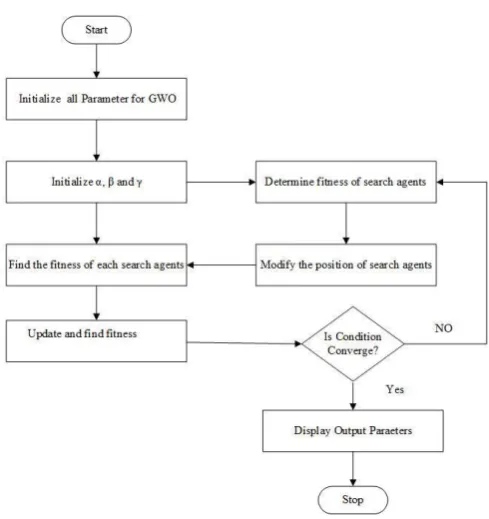
1. Initialize all GWO algorithm input parameters such as seek agents no (size of the population), the controller parameter size of the system (size of the problem), lower and upper seek space boundaries, size of the superiority variables and maximum number of iteration for this algorithm.
2. Seek agents of grey wolves (i.e. control system variables such as KP, KI and KD) are generated randomly in the seek space between lower and upper boundaries during the initialization process.
3. Calculate each seek agent's fitness and allocate in the seek space alpha, beta, delta wolves.
4. Adjust the alpha, beta and delta positions
5. Adjust the locations of seek agents together with omega 6. Eventually, alter the control variables for each seek agent (KP, KI, and KD).
7. Test whether or not any seek agent reaches the seek space and replace the randomly generated feasible solution set with infeasible solutions.
8. Filter the seek agent locations obtained for the next generation from the best value to the worst value in step five. 9. Switch to step four until the criteria for completion has been met.
The GWO algorithm tuned PID controller flow chart is illustrated in Fig. 4.
[image:3.595.304.549.43.303.2]The effectiveness of the proposed grey wolf optimized PID voltage and power factor controlled AC to DC system is tested in the MATLAB simulation in the next section.
Fig. 4.Flow chart for grey wolf optimization.
IV. SIMULATIONRESULTSANDDISCUSSIONS To check the effectiveness of the new grey wolf optimized PID voltage and power factor controlled AC to DC system, MATLAB simulation have been carried out in 2.3 GHz Intel i3 processor personal computer. The overall MATLAB simulation of PID controlled voltage and power factor controlled AC to DC system is shown in Fig.5. The system consists of AC input supply, AC-DC diode rectifier, boost DC-DC converter, variable resistive load, PID based voltage and power factor correction controller and parameter measurement systems.
Fig. 5.Overall MATLAB Simulation model for the grey wolf optimized PID based voltage and power factor
controlled AC to DC systems.
The simulation model of grey wolf optimized PID based voltage and power factor controller is shown in Fig.6.
[image:3.595.305.552.485.600.2]Fig. 6.Simulation model of the grey wolf optimized PID based voltage and power factor controller.
Table- I: Parameter optimzation results
Kp Ki Kd Best Worst Mean
Computation time (seconds) 1.976 0.2385 11.13 0.123 2.51 0.0124 60
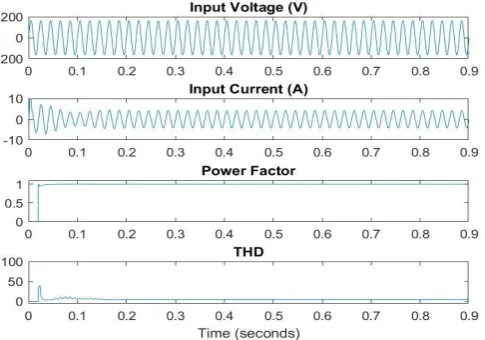
The proposed system has been tested for standard input voltage level such as 230v and110v with different loading conditions such as 500 and 1000. The voltage at input side, current at input side, power at input side, current at output end, voltage at output end, power at output end, efficiency, and total harmonic distortion for current is shown in Table II for 1000 and 500 loading conditions. The input and output results of the system at 1000 ohms and 500 ohms with 230 volt and 110 volts input is input is depicted in Fig.7, Fig.8, Fig.9 & Fig.10.
[image:4.595.41.290.206.257.2]Fig. 7.Output and input side waveforms of the system at 1000 ohms loading with input voltage of 230 volts.
Fig. 8.Output and input side waveforms of the system at 1000 ohms loading with input voltage of 110 volts.
Table II. Results of the system at 1000 ohms and 500 ohms with different input voltage
Electrical Load : 1000 ohms
Vin Iin (A)
Pin
(W) Vo
(V) Io
(A) Po
(W) PF η
(%) THD
(%)
110 1.56 172.4 389.9 0.38 152 0.99 88.2 4.3
230 0.79 180.5 389.9 0.38 152 0.99 84.2 4.9
Electrical Load : 500 ohms
110 2.90 318.8 390 0.78 304 0.99 95.4 5.2
230 1.46 334.4 389.9 0.78 304 0.99 90.9 6.5
[image:4.595.48.291.328.730.2] [image:4.595.311.551.333.704.2]International Journal of Innovative Technology and Exploring Engineering (IJITEE) ISSN: 2278-3075, Volume-9 Issue-2, December 2019
Fig. 10. Output and input side waveforms of the system at 500 ohms loading with input voltage of 110 volts.
From the Table II, it is observed that power factor of the system in maintain at 0.99, efficiency of the system is varying from 84 to 95 % with voltage varying from 110 volts to 230 volts, total harmonic distortion of the system is varying from 4.3 % to 6.5 % with voltage varying from 110 volts to 230 volts. From the results, it is ascertained that grey wolf optimized PID based voltage and power factor controller is outperformed in all aspects.
V. CONCLUSION
Grey wolf optimized PID based voltage and power factor controlled AC to DC system is designed, developed and tested in MATLAB simulation software. The overall simulation system is created in MATLAB platform in closed loop manner with grey wolf optimized PID controller. The proposed controller enhance power factor to 0.99, the output voltage always closed loop stable with less overshoot and less steady state error and total harmonic distortion for the input current is maintain at IEEE standard level. The designed controller is best suited controller in AC to DC system to enhance power factor and regulate the output voltage of the system.
REFERENCES
1. Quang et al. 2013, Zero-voltage switching current-fed flyback converter for power factor correction application, IET Power Electronics, 6(9), pp. 1971-1978, 10.1049/iet-pel.2013.0042.
2. Premkumar et al. 2019, „Fuzzy Anti-Windup PID Controlled Induction Motor‟ International Journal of Engineering and Advanced Technology, 9(1), pp.184-189.
3. Zheng et al. 2017, Long term effect of power factor correction on the industrial load: A case study, Australasian Universities Power Engineering Conference, pp.1-5, 10.1109/AUPEC.2017.8282382. 4. Thamizhselvan et al. 2017, Maximum power point tracking algorithm
for photovoltaic system using supervised online coactive neuro fuzzy inference system, Journal of Electrical Engineering, 17 (1), pp.270-286. 5. Fang Lin Luo 2005, Single-stage power factor correction AC/DC
converter, International Power Engineering Conference, Singapore, 2, pp. 974-979, 10.1109/IPEC.2005.207049.
6. Premkumar et al. 2015, GA-PSO optimized online ANFIS based speed controller for Brushless DC motor, Journal of Intelligent & Fuzzy Systems, 28(6), pp. 2839-2850.
7. Mahmud et al. 2018, Improvement of Active Power Factor Correction Circuit for Switch Mode Power Supply Using Fly Back and Boost
Topology, International Conference on Computer and Communication Engineering, pp. 437-440, 10.1109/ICCCE.2018.8539335.
8. Premkumar et al. 2015, Online Fuzzy Supervised Learning of Radial Basis Function Neural Network Based Speed Controller for Brushless DC Motor, Lecture Notes in Electrical Engineering, 326, pp.1397-1405. 9. Vadde et al. 2017, Real implementation of synchronous boost converter with controller for power factor correction, Symposium (TENSYMP), pp. 1-4, 10.1109/TENCONSpring.2017.8070061.
10. Premkumar et al. 2018, Novel bacterial foraging-based ANFIS for speed control of matrix converter-fed industrial BLDC motors operated under low speed and high torque, Neural Computing and Applications, 29(12), pp.1411–1434.
11. Han et al. 2017, A quasi single-stage power factor correction converter based on a three-level boost converter, Annual Conference of the IEEE Industrial Electronics Society, pp. 669-674, 10.1109/IECON.2017.8216116.
12. John Prabu et al. 2016, Fuzzy supervised online coactive neuro-fuzzy inference system-based rotor position control of brushless DC motor, IET Power Electronics, 9(11), pp.2229 – 2239.
13. Garg et al. 2017, Novel closed loop control for power factor correction using magnetic energy recovery switch, Innovations in Power and Advanced Computing Technologies (i-PACT), pp.1-5, 10.1109/IPACT.2017.8244924.
14. Premkumar et al. 2014, Adaptive Neuro-Fuzzy Inference System based speed controller for brushless DC motor, Neurocomputing, 138, pp. 260-270.
15. Pham PhuHieu et al. 2017, DSP based digital control techniques for Interleaved Boost PFC converter, International Future Energy Electronics Conference and ECCE Asia (IFEEC 2017 - ECCE Asia), pp.456-459, 10.1109/IFEEC.2017.7992081.
16. Premkumar et al. 2016, Bat algorithm optimized fuzzy PD based speed controller for brushless direct current motor, Engineering Science and Technology, an International Journal, 19(2), pp.818-840.
17. Agrawal et al. 2018, Performance Analysis of Shunt Active Power Filter Based on PIDA Controller, International Conference on Micro-Electronics and Telecommunication Engineering (ICMETE), pp.126-129, 10.1109/ICMETE.2018.00038.
18. Alice Hepzibah et al. 2019, ANFIS current–voltage controlled MPPT algorithm for solar powered brushless DC motor based water pump, Electrical Engineering, https://doi.org/10.1007/s00202-019-00885-8. 19. Premkumar et al. 2018, Stability and Performance Analysis of ANFIS
Tuned PID Based Speed Controller for Brushless DC Motor, Current Signal Transduction Therapy, 13(1), pp.19-30.
20. Nazar ali et al. 2014, Performance Enhancement of Hybrid Wind/Photo Voltaic System Using Z Source Inverter with Cuk-sepic Fused Converter, Research Journal of Applied Sciences, Engineering and Technology, 7(19), pp.3964-3970.
21. Shyam et al. 2019, Symmetrically modified laddered H-bridge multilevel inverter with reduced configurational parameters, International Journal of Engineering and Advanced Technology, vol.9, no.1, pp.5525-5532.
22. Premkumar et al. 2018, Antlion Algorithm Optimized Fuzzy PID Supervised On-line Recurrent Fuzzy Neural Network Based Controller for Brushless DC Motor, Electric Power Components and Systems, 45(20), pp.2304-2317.
23. Nazar ali et al. 2014, An ANFIS Based Advanced MPPT Control of a Wind-Solar Hybrid Power Generation System, international review of modelling and simulations, 7(4), pp.638–643.
24. Premkumar et al. 2015, Speed control of Brushless DC motor using bat algorithm optimized Adaptive Neuro-Fuzzy Inference System, Applied Soft Computing, 32, pp.403-419.
25. Premkumar et al. 2013, Adaptive fuzzy logic speed controller for brushless DC motor, International Conference on Power, Energy and Control, pp. 290-295, 10.1109/ICPEC.2013.6527668.
26. Nazar ali et al. 2015, A Single phase high efficient transformer less inverter for PV Grid connected power system using ISPWM technique, International Journal of Applied Engineering Research, 10 (9), pp.7489-7496.
27. Premkumar et al. 2015, Fuzzy PID supervised online ANFIS based speed controller for brushless dc motor, Neurocomputing, 157, pp.76-90.
AUTHORSPROFILE
Dr.K. Premkumar is currently working as an Associate Professor in the department of Electrical and Electronics Engineering at Rajalakshmi Engineering College, Tamilnadu, India. His area of interests are soft computing, Artificial Intelligence, electrical machines, electrical drives, renewable energy.
Prema Kandasamy is working as an Assistant Professor in the Department of Electrical and Electronics Engineering in Thangavelu Engineering College, Tamilnadu, India. Her area of interests is power factor correction, controller for AC to DC systems, power quality.
M.Vishnu Priya is currently working as an Assistant Professor in the department of Electronics and communication engineering in Saveetha School of Engineering, Tamilnadu, India. Her area of interests is power system operation and control, power electronics for solar system.
.
P.Palani kumar is currently working as an Assistant Professor in the Department of Electrical and Electronics Engineering in Thangavelu Engineering College, Tamilnadu, India. His area of interests is control system, power electronics, power system .