Assessing flowability of small quantities of cohesive powder using distinct
element modelling
Massih Pasha
,
Colin Hare
,
Ali Hassanpour
, and
Mojtaba Ghadiri
Citation:
AIP Conf. Proc.
1542, 959 (2013); doi: 10.1063/1.4812092
View online:
http://dx.doi.org/10.1063/1.4812092
View Table of Contents:
http://proceedings.aip.org/dbt/dbt.jsp?KEY=APCPCS&Volume=1542&Issue=1
Published by the
AIP Publishing LLC.
Additional information on AIP Conf. Proc.
Journal Homepage:
http://proceedings.aip.org/
Journal Information:
http://proceedings.aip.org/about/about_the_proceedings
Top downloads:
http://proceedings.aip.org/dbt/most_downloaded.jsp?KEY=APCPCS
Assessing Flowability of Small Quantities of Cohesive
Powder using Distinct Element Modelling
Massih Pasha, Colin Hare, Ali Hassanpour and Mojtaba Ghadiri
Institute of Particle Science and Engineering, University of Leeds, Leeds, UK
Abstract. The characterisation of cohesive powder flowability is often required for reliable design and consistent operation of powder processes. This is commonly achieved by mechanical testing techniques on bulk powder, such as shear test, but these techniques require a relatively large amount of powder and are carried out at large pre-consolidation loads. Many industrial cases require small amounts of powders to be handled and processed, such as filling and dosing of capsules. In other cases, the availability of testing powders could be a limiting issue. It has been shown that under certain circumstances, indentation on a cohesive powder bed by a blunt indenter can give a measure of the resistance to powder flow (Hassanpour and Ghadiri 2007). In the present work, the ball indentation process is analysed by numerical simulations using DEM in order to investigate the operation window of the process in terms of indenter size and penetration depth. The flow resistance of the assembly, commonly termed hardness, is evaluated for a range of sample quantities and operation variables. A sensitivity analysis of bed height reveals that a minimum bed height of 20 particle diameters is required in order to achieve reliable measurements of hardness. It is also found that indenter sizes with diameters smaller than 16 particle diameters exhibit fluctuations in powder flow stress measurements. As the indenter size decreases, it moves closer to the size of bed particles. Therefore, rearrangements at the single particle level influence the force on the indenter, resulting in fluctuations, and possible compaction.
Keywords: Flowability; DEM, Indentation on powder bed, Cohesive powder. PACS: 81.20.Ev, 45.70.Mg
INTRODUCTION
The characterisation of cohesive powder flowability is often required for reliable design and consistent operation of powder processes. There exist a number of test methods for evaluation of flow behaviour of powders, such as the unconfined compression test [1], shear test [2] and a few recently developed techniques, such as the Sevilla powder tester [3], the raining bed technique [4], Freeman FT4 [5], Edinburgh powder tester [6] and Hosokawa Micron powder tester [7]. These test methods require a relatively large amount of powder. Furthermore, the most common test method, i.e. the shear cell, measures flow properties of bulk powder at relatively large pre-consolidation stresses. There are a number of industrial cases where small amounts of loosely compacted powders are handled and processed, such as filling and dosing of small quantities of powder in capsules and dispersion in dry powder inhalers. In other cases, the availability of testing powders could be an issue. For instance in nuclear and pharmaceutical industries, the amount of powder available for testing is limited due to ionising radiation risks for the former and cost of drug in its early development stage for the latter. Hassanpour and Ghadiri [8] proposed a test method based on ball indentation on a powder bed which can be performed on small amounts of loosely
compacted powders. In the present work, we investigate the criteria which define the minimum required sample quantity and the suitable indenter size range for the ball indentation test. To this end, sensitivity analyses have been performed by DEM simulation of the indentation process in order to study the localised stress/strain behaviour of powder around the indenter.
INDENTATION PROCESS
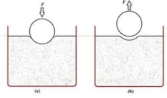
[image:2.612.356.476.571.642.2]For the experimental indentation process, a powder sample is consolidated into a cylindrical die which is made of low friction materials in order to reduce the effects of wall friction. The consolidated bed is then indented using a spherical indenter as shown in Figure 1 and the depth/load cycle is recorded.
Hardness, H, is given by the ratio of the maximum indentation load, F, to the projected area of the impression, A, which can be calculated based on the depth of the impression and indenter size,
(
2)
A
=
π
dh h
−
(1)where d is the diameter of the indenter and h is the final depth of the impression.
DEM SIMULATION OF THE
INDENTATION PROCESS
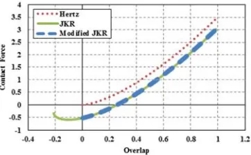
[image:3.612.318.500.245.285.2]The simulations were conducted using EDEM® software provided by DEM Solutions, Edinburgh, UK. The calculation of the contact forces of the particles were based on the Hertz analysis for the elastic regime. The adhesion force calculation between the particles were based on a modified version of the theory of Johnson et al. [9], referred to as JKR model. This was done to circumvent the problem associated with negative overlap. Figure 2 compares the Hertz elastic model with the JKR and the modified version of the JKR models. In the modified model, at the point of contact, the normal contact force immediately drops to 8/9 of the pull-off force, similar to the JKR model. The particle velocity reduces to zero at a point where the contact force reaches a maximum value and the loading stage is complete. In the unloading stage, the stored elastic energy is released and is converted into kinetic energy which makes the particle to move in the opposite direction. All the work done during the loading stage is recovered when the contact overlap becomes zero. Based on the JKR theory, at this point, the spheres remain adhered together and further work is required to separate the surfaces. The modified model does not consider this additional work and the contact for this model breaks once the overlap becomes zero. However the pull-off force required to break the contact is representative of the JKR theory.
FIGURE 2. Comparison of force-overlap behaviour of Hertz, JKR and modified JKR contact models.
For tangential contact force calculations the modified Mindlin model with no slip proposed by Di Renzo and Di Maio [10] is used.
[image:3.612.102.283.538.650.2]Particles with a mean diameter of 1 mm and a normal size distribution are generated inside a cylindrical die. The use of a size distribution rather than a mono disperse system, avoids the formation of ordered packing. The material properties are chosen so that they represent glass beads with a cohesive interaction (Material 1) and stainless steel (Material 2), as summarised in Table 1.
TABLE 1. Material properties used in the simulations.
Material Property Material 1 Material 2 Young’s modulus 55 GPa 182 GPa Poisson’s ratio (-) 0.25 0.3
Density (kg m-3) 2500 7800
The particles were generated within the die and allowed to settle under gravity. The assembly was then consolidated with a piston at a constant strain rate of 1 s-1. For all the simulations, the assembly was pre-consolidated to 10 kPa (ıpre = 10 kPa). Once the desired stress was achieved, the piston was unloaded with the same speed as that of the loading. The reason why 10 kPa pre-consolidation load was applied was because it was within the realistic range of experimental work, where results of other flowability techniques, e.g. uniaxial unconfined compression, have been reported. The indentation process was simulated using a cohesionless spherical indenter made of Material 1.
RESULTS AND DISCUSSION
FIGURE 3. Hardness as a function of dimensionless penetration for four different bed heights.
Bed heights of 20, 30 and 50 mm exhibit lower hardness values (about 6 kPa) than the 13 mm bed height (about 8 kPa) in Figure 3. Since for the larger bed heights a relatively constant hardness were obtained, the simulations for this range of bed heights were not influenced by confinement at the base.
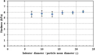
[image:4.612.324.514.199.309.2]With the minimum sample size in terms of bed height and bed diameter determined, a sensitivity analysis for a range of indenter sizes were carried out to reveal the effect of indenter size on hardness measurement. Different indenter sizes were used here to simulate ball indentation on the 20 mm bed height. Figure 4 shows average hardness as a function of indenter size with the with error bars indicating standard deviation of fluctuations.
FIGURE 4. Average hardness with error bars indicating standard deviation for different indenter sizes.
By increasing the indenter size, the fluctuations decrease in the hardness measurement. This can be attributed to the fact that the smaller indenters are comparable in size to single particles, and rearrangements at the single particle level influence the force on the indenter throughout the indentation process, resulting in instabilities. It can be concluded that the indenter size should be greater than 13 particle diameters, with 16 diameters being adequate.
With the minimum sample size and suitable indenter size determined, the operation window for the penetration depth was investigated by calculation of
hydrostatic stress inside a dynamic bin just below the indenter whose position was fixed relative to the indenter, i.e. it moved with the indenter. The size of the bin was 5.2, 5.2 and 4.2 mm in x, y and z directions, respectively. Figure 5 shows the hydrostatic stress inside this bin for indenter diameters of 7, 16, 19 and 22 mm, bed height of 20 mm and bed diameter of 45 mm.
FIGURE 5. Hydrostatic stress inside the dynamic bin as a function of dimensionless penetration for different indenter sizes.
For the suitable indenter sizes, i.e. 16, 19 and 22 mm indenters, the hydrostatic stress increased initially up to a dimensionless penetration of about 0.1. Beyond this point the stress had a relatively constant average value, although fluctuating. This is the region of interest where the flow stress must be calculated. For dimensionless penetrations beyond 0.5, the stress started increasing again, which indicates the influence of a number of factors depending on the proximity of the walls and the base and ultimate penetration depth. For the 7-mm indenter, it was difficult to determine the range for constant value of hardness due to large fluctuations.
CONCLUSIONS
[image:4.612.101.291.411.522.2]effect of different indenter sizes to be analysed and compared. The penetration depth should be sufficiently large to cause notable bed shear deformation. It was found that this minimum penetration depth was approximately equal to 0.1 in terms of dimensionless penetration. A sensitivity analysis of indenter size revealed that indenters with diameters smaller than 16 particle diameters exhibit fluctuations in hardness measurements, whereas indenters with a diameter of up to 22 particle diameters result in stable hardness values, providing the minimum sample criteria were met. As the indenter size decreases, it approaches the size of bed particles. Therefore, rearrangements at the single particle level influence the force on the indenter throughout the indentation process, resulting in fluctuations in hardness. With very large indenters comparable in size to the die, the measurement of hardness may be affected by the wall.
REFERENCES
1. L. Parrella, D. Barletta, R. Boerefijin and M. Poletto,
KONA 85, 178-189 (2008).
2. D. Schulze, “A new ring shear tester for flowability and time consolidation measurements” in International Particle Technology Forum, 1st International Particle Technology Forum, USA, 1994, pp. 11-16.
3. A. Castellanos, J.M. Valverde and M.A.S. Quintanilla,
KONA 22, 66-81 (2004).
4. B. Formisani, P. Bernado, R. Girimonte and A. Minnicelli, “The bed support experiment in the analysis of the fluidization properties of fine solids” in World Congress on Particle Technology, 4th World Congress on Particle Technology, Australia, 2002, pp. 66-81. 5. R. Freeman, Powder Technology 174, 25-33 (2007). 6. T.A. Bell, E.J. Catalano, Z. Zhong, J.Y. Ooi and J.
Michael, “Evaluation of the Edinburgh Powder Tester The University of Edinburgh , Great Britain” in
PARTEC, PARTEC 2007, Germany, 2007, pp. 1-5. 7. E.C. Abdullah and D. Geldart, Powder Technology 102,
151-165 (1999).
8. A. Hassanpour and M. Ghadiri, Particle & Particle Systems Characterization 24, 117-123 (2007). 9. K.L. Johnson, K. Kendall and A.D. Roberts Proceeding
of the Royal Society A324, 178-189 (1971). 10. A. Di Renzo and F.P. Di Maio, Chemical Engineering