Article
Needle with Polygonal Structure of
Micro-Channel for Stress and Blood or Drug Flow
Optimization
Mohd Danial Ibrahim
1,*
, Yana Shaheera Yunos
1, Nobuo Watanabe
2,
Nur Alia Athirah Mohtadzar
3, Siti Noor Haizum Semait
4, Andrew Ragai Henry Rigit
1,
Yuta Sunami
5, Wong Lee Kwang
1, Mohd Rahmat A. Rahman
1,
and Muhammad Zaidi Mohtar
11 Department of Mechanical & Manufacturing, Universiti Malaysia Sarawak, 94300 Kota Samarahan, Malaysia
2 Department of Bioscience and Engineering, Shibaura Institute of Technology, Saitama Prefecture 337-8570, Japan
3 Department of Electrical & Electronic, Universiti Malaysia Sarawak, 94300 Kota Samarahan, Malaysia 4 Press Metal Bintulu Sdn. Bhd., 97000 Samalaju, Malaysia
5 Department of Mechanical Engineering, Tokai University, Kanagawa Prefecture 259-1207, Japan *E-mail: [email protected] (Corresponding author)
Abstract. This paper presents micro-needle with different tip and inner structure of the needle for optimizations of pain stresses and drug or blood deliveries. The micro-needle comes with several design’s parameters of length ranging from 5mm to 50mm and diameter ranging from 100µm to 200µm. A hollow micro-needle with four different tip designs which are 10°, D3-2, D6 and Quadruple are also designed to optimize the pain stresses parameters. In order to improve the flow deliveries, the inner structure of the channel is modified into various polygonal shape which is square, hexagon and dodecagon. It shows that, having less contact surface area between the skin and micro-needle’s tip and polygonal shape of inner channel has better performance for both of the objectives. These feasible region of average velocity and stress of the micro-needle have satisfied in determining the best design for tip and inner channel of the micro-needle under certain conditions and constraints. The three-dimensional geometry study had improved the insertions performance and efficiencies in painless drug or blood deliveries.
Keywords: Micro-needle, drug delivery, blood delivery, polygonal micro-needle, quadrupletip micro-needle.
ENGINEERING JOURNAL Volume 21 Issue 4 Received 30 September 2016
Accepted 17 January 2017 Published 31 July 2017
1.
Introduction
Injecting drug and blood withdrawing techniques are obtained either from arteries or veins. By using hypodermic needle to penetrate human skin until it reaches the arteries or veins is surely uncomfortable and painful. From the beginning of the realization of painless needle from mosquito’s mechanism of blood withdrawal, lots of research is done to improve the efficiency of the micro-needles for drug delivery and blood withdrawal from various sizes of needle and designs. Needles are defined as sharp hypodermic needle that has a function to be painless while completing the task of penetrating the human outermost skin to withdraw blood or injecting fluid into the blood stream [1-4]. From hypodermic needles to the current conventional needle, the advancement of the researches leads to the technologies of micro-needles in improving the flow and performance while completing the task of penetrating the human outermost skin [5]. In general, micro-channels are regarded as an effective method for the field of heat transfer in the application of various fluids and fluid velocity [6]. Furthermore, this might gives improvement in dynamic characteristics by modifying the geometries of the micro-channel, by changing the inner polygonal shape with different dimensions, similarly as how the previous researchers conducted in modifying geometries and dimensions to gain drastic performance improvements [7-8].
Human skin is the largest organ of the human body and one of the complex tissues of the human body which has different functions components and structure. Structure of outermost layer, stratum corneum is very complex and acts as a barrier. These methods are used in previous research, which makes the delivery more successful. Problems are encountered when drug is too complex and difficult to be absorbed from the skin to the vessel. This layer is composed of cornified dead cell which is 20-40µm thick [9]. Human skin in each part itself has difference in their young modulus and differs in each part of human body as it exhibits the properties of non-homogenous, anisotropic nonlinear and viscoelastic [10]. The level of hydration of human skin also affect the young modulus and level of pain when the needle is about to penetrate the skin [11].
Penetrating human skin with a hypodermic needle is painful and uncomfortable. A low-invasive needle is very much desired in medical field in order to do lot of activities that involve needle. By imitating mosquito fascicle, researcher has put their considerable effort in developing micro-needles in order to replace the normal and traditional hypodermic needle. From hypodermic needle, the advancement of the researches leads to the technologies of micro-needles with the efforts to bypass the stratum corneum that enhance drug penetration. Penetrations up to 1.5mm are considered to be painless [12]. Sharper tip of needle ease the penetration process as the generated stress is only little compared to the blunt tip. Stratum corneum, which is 10-15µm, the outer layer of skin, gives more advantage to micro-needle compared to the traditional hypodermic needle as the conventional needle that pass this layer of skin does transmit the drugs effectively but there is a possibility of infection and pain. While, micro-needles which can be fabricated long enough, pass this layer, results in less pain, infection nor injuries [13].
2.
Methodology
Figure 1 shows the micro-needles with inner channel design of circular, square, hexagon, and dodecagon, respectively. Previous researchers focus on making differences on non-edges, circle and edges, and square channels only. The research does not cover the number of edges of the inner channels. Therefore, these designs are proposed to investigate the effects that will occur when more variation on the inner channels edges is purposely designed for micro channels. Several micro-needle’s tip designs are also designed with the parameter of 100μm and 150μm inner-diameter with three different channel length which is 10mm, 25mm and 50mm. The medium for the flow improvement research simulation is blood and drug represented by water.
The biggest vessel diameters in human body are veins, which ranges from 800µm-1.8mm where the venous blood flows significantly at 1.5-7.1cm/sec. The velocity of the inlet was assumed to be lower than the non-Newtonian flow properties where the diameter of the microneedle ranges from 100 µm-200 µm, thus the velocity decided was 0.01m/s [14].
biocompatibility of the material. The surface roughness of polysilicon is 0.5 while titanium is having surface roughness of 0.1.
Fig. 1. Micro-needle channel inner designs.
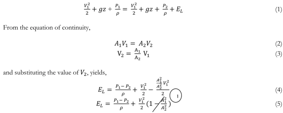
This research focuses more on the fluid flow velocity and its energy losses in micro-needles with respect to the design parameters and slip length applied according to micro-needle’s length. The physic settings for the simulation is using laminar two-phase flow. Blood is comprised by plasma and red blood cells. The main content of blood is red blood cells or erythrocytes which accounts for 45% of blood volume, 95% of blood tangible composition and more than 99% of the particulate matter in blood. Blood is regarded as a two-phase flow system of erythrocytes suspended in plasma for microcirculation since the size of erythrocytes are same as the capillary diameter in microcirculation. Erythrocytes aggregation as well as deformability has a great influence on blood rheological properties especially at low blood flow rate [15]. The energy equation for the energy losses in fluid flow is applied as in Eq. (1), where energy equation considering energy losses, EL is as follows.
(1)
From the equation of continuity,
(2)
(3)
and substituting the value of , yields,
(4)
(5)
The area of the channel remained the same along the micro-needle. The final equation that can be obtained is as the following and applied to find the energy losses for the fluid flow.
(6)
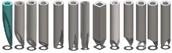
Figure 2 shows the 10°, 20, 30, 40, D1, D2-1, Quadrupletip, D3-2, D5-2, D6, D7-2, D9 and D10 micro-needle which are used for the stress simulation optimization. These design variables are proposed in this research due to fact that conventional needles used in the medical field currently are only 10° needle tip. It is assumed to be the most practical and less painful tip due to its lowest surface contact area. However, we included more design on tip needle with low contact area to compare their performance with the conventional tip needle. These micro-needles designed are a hollow cylinder with a dimension of 300μm outer diameter, and 180μm inner diameter. Penetrating human skin, the simulation of the maximum stress on human skin resulted by penetrating micro-needles by 0.5mm downward was simulated by imitating mosquito proboscis when penetrating human skin for blood sucking purpose [16].
The micro-needles are penetrating the rubber perpendicularly to the rubber surface in order to find the maximum value of the parameters mention above. However, it is best if the piercing angle of the micro-needles is in 45° to the skin surface; as this is claim to be the best angle to withdraw the human blood efficiently [17]. The micro-needles are set to fix and rigid mode. They are also set to be the reference geometry by -0.5mm at y-axis.
[image:3.595.81.534.330.511.2]Fig. 2. Micro-needle tip designs.
Table 1 and Table 2 show the properties of fluid (drug and blood) and applied physics on the model of the simulation for the boundary condition. The validation of the simulation can be seen through the element quality of the complete mesh showed in Table 3. The domain elements statistics shows that the average element quality is 0.7856. The value of the average element quality towards 1 provides a better numerical results. Figures 3 and 4 show the element quality histogram and the meshed model of dodecagon channel.
Table 1. Fluid properties.
Properties Fluid
Blood Water
Density, ρ [kg/m3] 1060 1000
Dynamic viscosity, µ [Pa.s] 0.00400 0.00089
Table 2. Boundary conditions in the simulation.
Boundary conditions
Applied physics
Laminar two-phase flow, moving mesh (tpfmm)
Navier-slip, β 0.2*h
Laminar inflow uPavg 0.01 m/s
0 0 Pa
Applied study Time-dependent
Applied mesh Mesh size User-controlled mesh Solid Normal
Non solid Fine
Table 3. Model mesh statistics
Statistics Complete mesh
Element type All elements
Tetrahedral elements 385160
Triangular elements 59962
Edge elements 9364
Vertex elements 28
Domain element statistics
Number of elements 385160
Minimum element quality 0.1377
Average element quality 0.7856
Element volume ratio 0.04496
Mesh volume 28630.0 mm3
Maximum growth rate 3.487
[image:4.595.168.455.86.174.2] [image:4.595.70.526.567.761.2]Fig. 3. Element quality histogram.
Fig. 4. Meshed model of dodecagon channel.
3.
Results and Discussions
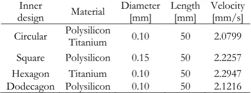
The velocity simulation result of circular, square, hexagon and dodecagon for drug delivery is sorted from the highest velocity simulated for each material, length and diameter. From these 96 sets of micro-needles, the chosen micro-needles based on performance is tabulated in Table 4. The table shows that using square shape, polysilicon, 0.15mm diameter and 50mm length produced the highest velocity. The velocity simulation result from circular, square, hexagon and dodecagon for blood delivery is sorted from the highest velocity simulated for each material, length and diameter. Based on Table 5, it shows that using hexagon shape, titanium, 0.10 diameter and 50mm length produced the highest velocity.
Table 4. Drug flow performance.
Inner
design Material Diameter [mm] Length [mm] Velocity [mm/s] Circular Polysilicon Titanium 0.10 50 2.0799
Square Polysilicon 0.15 50 2.3220 Hexagon Polysilicon 0.10 50 2.2947 Dodecagon Polysilicon 0.10 50 2.1344
Table 5. Blood flow performance.
Inner
design Material Diameter [mm] Length [mm] Velocity [mm/s] Circular Polysilicon Titanium 0.10 50 2.0799
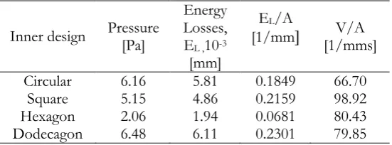
[image:5.595.194.402.78.181.2] [image:5.595.196.398.211.335.2] [image:5.595.172.424.523.613.2] [image:5.595.169.426.650.745.2]Table 6 and Table 7 show the pressure obtained in drug and blood flow delivery simulation. The energy losses is then calculated using the Eq. (6) as shown in previous section.
In drug flow delivery, using square inner design has higher velocity compared to other designs. It shows that when square inner design is used, it has the lowest energy losses which is 1.41x10⁻³ mm along
the micro-needle. On the other hand, it also shows that when the value of velocity per area increases, the energy losses per area has lower value respectively.
In blood flow delivery, using hexagon inner design has higher velocity compared to other designs. It shows that using hexagon inner design, lower energy losses can be obtained which is 1.41x10⁻³ mm along
the micro-needle. On the other hand, it also shows that when the energy loss per area decreases, the velocity per area has lower value respectively. These tables can be summarized as that wall interaction is higher than the interaction’s area which are applied to the inner designs of the micro-needle.
Table 6. Drug flow relationship performance.
Inner
design Pressure [Pa]
Energy Losses, EL ,10-3
[mm]
EL/A
[1/mm [1/mms] V/A
Circular 1.61 1.61 0.0512 66.62 Square 1.41 1.41 0.0627 103.2 Hexagon 2.07 2.07 0.0727 80.43 Dodecagon 1.69 1.69 0.0636 80.32
Table 7. Blood flow relationship performance.
Inner design Pressure [Pa]
Energy Losses, EL ,10-3
[mm]
EL/A
[1/mm [1/mms] V/A
Circular 6.16 5.81 0.1849 66.70 Square 5.15 4.86 0.2159 98.92 Hexagon 2.06 1.94 0.0681 80.43 Dodecagon 6.48 6.11 0.2301 79.85
As the fluid flows through a channel, the fluid experiences some resistance due to some energy losses, usually caused by secondary flows. As time passes, the increase of viscosity affected the velocity in a channel. Mainly, the viscosity causes loss of energy in the flows due to friction which is related to the Reynolds number for the fluid flow, surface roughness of the channel and the geometry of the channel.
In blood flow rheology, the elevation in red cell hematocrit, eventually increase the blood viscosity. Thus, increase the resistance to blood flow. If clotting mechanisms are stimulated in the blood, platelet aggregation and interactions with plasma proteins occur. This leads to entrapment of red blood cells and clot formation, which dramatically increases the blood viscosity. The higher viscosity of the fluid, the higher resistance to flow because the fluid’s particle have more force attraction between them. These leads to be having more cohesion and internal friction which how often the particles of a fluid slip past each other. Thus, decreasing the flow rate of the fluid’s flow [18-22].
The relationship of velocity-energy losses can be further explained in the relationship of V/A-EL
graphs for both drug and blood delivery. The highest velocity obtained are square for drug delivery and hexagon for blood delivery. The fluid-wall interaction has been minimized or exterminated, thus, the energy losses is small in these micro-needles size. The value per area is generalized for all micro-needle regardless of its inner design parameters. In drug delivery, square inner design has smallest value in velocity per area but in order to achieve the smallest value in energy losses per area, the inner design has to be circle. In blood delivery, hexagon inner design has smallest value in energy losses per area but in order to achieve the smallest value in velocity per area, the inner design has to be square.
[image:6.595.176.421.253.355.2] [image:6.595.161.437.396.498.2]shear stress [23]. Depending on the geometry and hydrodynamic conditions of the flow, there is a transient change of flow behavior and blood viscosity. Blood is a non-Newtonian fluid, which means that the viscosity of blood is not constant, and it depends on shear rate [24].
As pointed out by Fahraeus and Lindqvist, tube diameter-dependent changes in viscosity are related to the axial accumulation of red blood cells in the flowing blood. During laminar flow through a tube, the concentric layers of plasma shearing against each other when it is caught between two layers [25]. This multiphase fluid nature of blood is the physical reason behind the Fahraeus effect where the correlation is when the tube diameter is decreased, the average velocity of blood is increased and so does the wall shear stress but decreased in apparent blood viscosity [24-25]. The relationship shows in both Fig. 5 and Fig. 6. This type of migration is known to be due to the formation of a cell-free layer near the wall and shear induced diffusion caused by a decrease of granular temperature at the center of the tube due to inelastic collisions hence drop of pressure through the narrow vessel [25]. This relationship can be applied to the polygonal shape of channel where the hydraulic diameter of polygonal channel has less area compared to the total are of diameter of circular channel. Thus the resultant average velocity in edges channel is higher than in non-edges channel.
Fig. 5. Relationship of tube diameter on the relative viscosity of flowing blood [26].
[image:7.595.206.383.275.495.2] [image:7.595.188.404.537.721.2]Another factors, which contribute flow behavior of blood in flow channel, are the interaction of erythrocytes and wall surface, the geometry of flow channel and the contour of inner surface of flow channel. This also can be applied to drug as well as drug contain molecules in such solution. The interaction of molecules in both drug and blood may interact with the surface of the wall and temporarily stick on the surface. The shear stress may change the interaction through the alteration of spatial organization of the molecules. As for the contour of inner surface of flow channel, the irregularly shaped inner surface of living microvessels provides hydrodynamically smaller effective diameters of their lumina. This can be related to the polygonal channel which mimicking the irregular shape of the inner surface of the channel.
The painless micro-needle designs are based on the maximum stress results between the micro-needle designs. It shows that quadrupletip produce less stress than the other 12 micro-needle tip designs.
Table 8-10 show the simplified way to view the differences of each micro-needle resulted when penetrates the rubber for the maximum strain and displacement result of each micro-needle.
It shows that quadrupletip micro-needle produces lowest stress and strain result. While for the maximum displacement result, quadrupletip micro-needle ranked 7/13 lowest displacement results.
Table 8. Comparison of 10°, Quadruple, D3-2 and D6 tip micro-needle.
Micro-needles
Stress [N/mm2] 52.804 46.752 221.00 212.56
Strain [mm] 2.182 x 10⁻² 2.167 x 10⁻² 1.156 x 10⁻¹ 8.953 x 10⁻²
Displacement [mm] 2.000 x 10⁻² 1.705 x 10⁻¹ 6.400 x 10⁻² 2.825 x 10⁻¹
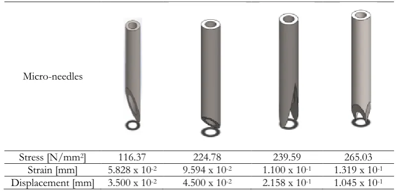
Table 9. Comparison of 20°, 40°, D1 and D5-2 tip micro-needle.
Micro-needles
Stress [N/mm2] 116.37 224.78 239.59 265.03
Strain [mm] 5.828 x 10⁻² 9.594 x 10⁻² 1.100 x 10⁻¹ 1.319 x 10⁻¹
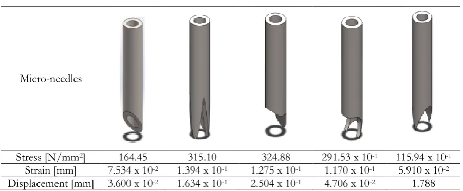
[image:8.595.82.506.284.463.2] [image:8.595.97.496.498.692.2]Table 10. Comparison of 30°, D2-1, D9, D7-2 and D10 tip micro-needle.
Micro-needles
Stress [N/mm2] 164.45 315.10 324.88 291.53 x 10⁻¹ 115.94 x 10⁻¹
Strain [mm] 7.534 x 10⁻² 1.394 x 10⁻¹ 1.275 x 10⁻¹ 1.170 x 10⁻¹ 5.910 x 10⁻²
Displacement [mm] 3.600 x 10⁻² 1.634 x 10⁻¹ 2.504 x 10⁻¹ 4.706 x 10⁻² 1.788
4.
Conclusion
This paper concludes that hexagon inner structure of micro-needle has better delivery for blood, while, square inner structure of needle has better delivery for drug. It also shows that quadrupletip micro-needle is the best design for pain optimization with lowest maximum value of stress compared to other designs. This implies that the designs had improved the insertion performance and potentially the painless blood withdrawal efficiency. Future works can be done by using quadrupletip micro-needle attached to a micro-pump in calibration with medical industry.
Acknowledgement
The present work was partially funded by Fundamental Research Grant Scheme, Ministry of Education Malaysia, Grant No: FRGS/TK01 (01)/1059/2013(05) and UNIMAS Special Short Term Grant, Grant No: F02/SpSTG/1386/16/28. The authors also declares that there is no conflict of interest regarding the publication of this paper.
References
[1] A. Oki, M. Takai, H. Ogawa, Y. Takamura, T. Fukasawa, J. Kikuchi, Y. Ito, T. Ichiki, and Y. Horiike, “Healthcare chip for checking health condition from the analysis of trace blood collected by painless needle,” J. Appl. Phys., vol. 42 pp. 3722-27, 2003.
[2] H. Ogawa, M. Nagai, J Kikuchi, and Y. Horiike, “Blood painless collection system equipping detection functions for search of vein,” in 7th Int. Conf. Miniaturized Chemical and Biochemical Analysis Systems, 741-3, Squaw Valley, CA, USA, 2003.
[3] S. Henry, D. V. McAllister, M. G. Allen, and M. R. Prausnitz, “Micromachined needles for the transdermal delivery of drugs,” in Proc. IEEE Micro Electro Mechanical Systems, MEMS’98, Heidelberg, Germany, 1998, pp. 494-8.
[4] K. Oka, S. Aoyagi, Y. Arai, Y. Isono, G. Hasiguchi, and H. Fujita, “Fabrication of a micro needle for trace blood test,” Sensor Actuators A, vol. 97-98, pp. 478-85, 2002.
[5] S. Khumpuang, M. Horade, K. Fujioka, and S. Sugiyama, “Geometrical strengthening and tip-sharpening of a microneedle array fabricated by x-ray lithography,” Microsyst. Technol., vol. 13, pp. 209-14, 2007.
[6] F. Ismail, A. I. Rashid, and M. Mahbub, “CFD analysis for optimum thermal design of a carbon nanotube based micro-channel heatsink,” Engineering Journal, vol. 15, no. 4, pp. 11-22, 2011.
[image:9.595.73.524.104.290.2][8] H. Hashimoto, M. Ochiai, T. Namba, and M. D. Ibrahim, “Optimum design of high speed thrust air bearing using groove geometry and dimensions as design variables,” in Proc. of the Intl. Joint Tribology Conference, Memphis, Tennessee, USA, 2009.
[9] M. K. Ramasubramanian, O. M. Barham, and V. Swaminathan, “Mechanics of mosquito bite with application to microneedle design,” Bioinspiration & Biomimetics, vol. 3, pp. 1-10, 2008.
[10] F. M. Hendriks, D. Brokken, C. W. J. Oomens, F. P. T. Baaijens, and J. B. A. M. Horsten. (2005).
Mechanical Properties of Different Layers of Human Skin [Online]. Available: https://www.researchgate.net/publication/260301973, Accessed on: 29 September 2016.
[11] J. V. Kuilenburg, M. A. Masen, and E. V. D. Heide, “Modeling of human skin: what value to use for the modulus of elasticity,” Journal of Engineering Tribology, vol. 227, no. 4, pp. 1-13, 2012.
[12] S. Khumpuang, M. Horade, K. Fujioka, and S. Sugiyama, “Geometrical strengthening and tip-sharpening of a microneedle array fabricated by x-ray lithography,” Microsyst. Technol., vol. 13, pp. 209-14, 2007.
[13] A. Neha, S. Kamaljit, B. Ajay, and G. Tarun, “Microneedle: As a future prospective tool,” International Research Journal of Pharmacy, vol. 3, no. 1, pp. 102-105, 2012.
[14] M. Klarhofer, B. Csapo, Cs. Balassy, J. C. Szeles, and E. Moser, “High-resolution blood flow velocity measurements in the human finger,” Magnetic Resonance in Medicine, vol. 45, pp. 716-719, 2001.
[15] B. Chen, F. Guo, and H. Xiang, “Visualization study of motion and deformation of red blood cells in a microchannel with straight, divergent and convergent sections,” J Biol Phys, vol. 37, pp. 429-440, 2011.
[16] S. N. Semait, “Minimizing pain stresses using micro-needles—An application from mosquito syringes,” U.S. thesis, Dept. of Mechanical and Manufacturing, Universiti Malaysia Sarawak, Kota Samarahan, Sarawak, Malaysia, 2013.
[17] A. R. Osman, “Fundamental study on the mechanism of blood withdrawal of mosquito,” U.S. thesis, Dept. of Mechanical and Manufacturing, Universiti Malaysia Sarawak, Kota Samarahan, Sarawak, Malaysia, 2008.
[18] R. E. Klabunde. (2011). Viscosity of Blood, Cardiovascular Physiology Concepts [Online]. Available: http://www.cvphysiology.com, accessed on 16/09/2016, Accessed on: 19 September 2016.
[19] G. D. Lowe, A. J. Lee, A. Rumley, J. F. Price, and F. G. Fowkes. (1997). Blood Viscosity and Risk of Cardiovascular Events: The Edinburgh Artery Study [Online]. Available: https://www.ncbi.nlm.nih.gov/pubmed/9012704, Accessed on: 19 September 2016.
[20] G. Cluffetti, G. Schillaci, R. Lombardini, M. Pirro, G. Vaudo, and E. Mannarino. (2005). Prognostic Impact of Low-Shear Whole Blood Viscosity in Hypertensive Men [Online]. Available: https://www.ncbi.nlm.nih.gov/pubmed/15667579, Accessed on: 19 September 2016.
[21] G. D. Sloop. (1996). A Unifying Theory of Atherogenesis [Online]. Available: https://www.ncbi.nlm.nih.gov/pubmed/8910882, Accessed on: 19 September 2016.
[22] E. Rillaerts, L. van Gaal, D. Z. Xiang, G. Vansant, and I. D. Leeuw. (1989). Blood Viscosity in Human Obesity: Relation to Glucose Tolerance And Insulin Status [Online]. Available: https://www.ncbi.nlm.nih.gov/pubmed/2695480, Accessed on: 29 September 2016.
[23] N. Maeda, “Erythrocyte rheology and oxygen transfer in microcirculatory system,” J Biorheol, vol. 29, pp. 2-5, 2015.
[24] D. Gidaspow and J. Huang, “Kinetic theory based model for blood flow and its viscosity,” Annals of Biomedical Engineering, vol. 37, no. 8, pp. 1534-1545, 2009.
[25] L. N. Toksvang and R. M. G. Berg, “Using a classic paper by Robin Fahraeus and Torsten Lindqvist to teach basic hemorheology,” Adv Physiol Educ, vol 37, pp. 129-133, 2013.
[26] R. Fahraeus and T. Lindqvist, “The viscosity of the blood in narrow capillary tube,” Am J Physiol, vol. 96, pp. 562-568, 1931.
![Fig. 5. Relationship of tube diameter on the relative viscosity of flowing blood [26]](https://thumb-us.123doks.com/thumbv2/123dok_us/8108026.235606/7.595.206.383.275.495/fig-relationship-tube-diameter-relative-viscosity-flowing-blood.webp)