Article
Waste Foundry sand Mineralogical Characterisation:
The Impact of Cast Alloy, Casting Temperature and
Molding Additive on the Nature Waste Foundry Sand
Kolela J. Nyembwe
a, Mamookho E. Makhatha
b,*and Kulani Mageza
Department of Metallurgy, School of Mining, Metallurgy and Chemical Engineering, Metal Casting Technology Station, University of Johannesburg, South Africa
E-mail: a[email protected], b[email protected] (Corresponding authors)
Abstract. The metal casting industry discharges huge volumes of waste foundry sand yearly.
It was estimated to be 250 thousand tons of spent silica foundry sand for the existing 200 casting facilities in South Africa. Even though, establish documents exist in regards to the foundry sand composition, few well documented theories are available in regards to changes or mutations taking place after casting process. Four waste silica casting sands were qualitatively analyzed for they mineralogical phases composition using the X-ray diffraction (XRD). The investigation was conducted on various waste casting sand alloy including aluminum, cast iron, high chrome and steel. The result revealed a significant compositional difference related to the molding binder and casting temperature. Different silica phase’s polymorph, related to the various alloy casting temperature, were observed in waste sand samples. Theses phases included alpha quartz, tridymite, and alpha cristobelite. The molding binder favored the crystalisation of bentonite related mineral such as periclase, microcline and wustite, within the greensand system. The chemically bonded sand exposed the presence of anorthite as the only existing mineralized phase in the resin sand. The mineralogical content of the waste foundry sand provides information on the molding binder used. In addition to that, silica polymorph it informs about the pouring temperature related to the cast alloy.
1.
Introduction
Foundry operation mainly involves the pouring of molten metal into refractory molds, holding the metal in specific dimensions and tolerances until solidification (Kogel et al., 2006) [1]. Molds are cavities made by shaping refractory material including silica, chromite, zircon and olivine sand (Insley & Fréchette, 1995) [2]. The use of silica sand as the main molding aggregate is explained by its availability and low cost as compared to the others refractory aggregates (Wang et al., 2016). Foundry operations generates different type of waste including off gases from melting, bag house dust and sludge from the molding process. Lastly the shakeout process produced waste molding sand (Diane, 1996) [3] which is usually recycled within the foundry for molding purpose. However, a portion of sand is removed from the molding line as the sand is to some extend contaminated by the casting process: thin film of unburnt carbon and residual binder (Recycled material research center, 2012). In addition to that, the sand is exposed to the high temperature (molten metal) during its life time in the foundry, rendering it unsuitable for molding (Dayton et al., 2010) [4].
The South African foundry industry is currently composed of approximately 200 hundred casting facilities (Davies , 2015) [5]. It was estimated that, the industry yearly discards 250 and 25 thousand of waste sand, individually for silica and chromite waste molding sand. Due to the scarcity of available landfill and environmental pressure, dumping of waste sand has been burden for most of local foundry. The previous studies conducted revealed the waste sand to be mainly composed of silica in form of silicon dioxide, followed by other oxides including aluminum, iron and
magnesium
(Pasetto & Baldo, 2015 [6], Faisal & Ahmed,
2014 [7], Alves et al., 2014 [8], Basar & Aksoy, 2012 [9] and Kassim et al., 2005 [10])
In addition to that, several studies highlighted to the effect of casting process on the chemistry of the sand, more especially, in regards to nonferrous alloy (Alves et al., 2014 [8]; Dungan & Dees, 2009 [12] and Deng, 2004 [11]). However, few establish documents exist in regards to mineralogical changes taking place after the casting process in relation to the casting temperature and molding additives. The aim of this work is to investigate mineral phase’s transformation of different casting sand alloys. Since, the reuse of this foundry by product contributes to a greener environment, understanding its chemical mineralogy is of relevance to proper reuse and recycle of such a material.2.
Materials and Methods
2.1. Material
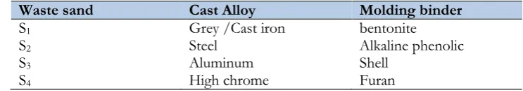
[image:2.595.140.456.584.744.2]Table 1. Waste sand cast alloy and molding binder.
Waste sand Cast Alloy Molding binder
S1 Grey /Cast iron bentonite
S2 Steel Alkaline phenolic
S3 Aluminum Shell
S4 High chrome Furan
2.2. Methods
The received samples were moisture removed using an oven at 1050 Celsius for four hours. The X-ray diffraction patterns associated to different mineral (chemical) phases were obtained after the sand samples were finely grounded to less than 150 micron (Schönenberger et al., 2012) [13]. The qualitative mineralogical sand composition was determined using the XRD Rigaku Ultima IV, equipped with PDXL analysis software. The operating condition were Cu-Kα (Cu tube) at 30 Kv ration and 25 mA.
3.
Results and Discussion
3.1. Results
The mineralogical composition of the various casting sands are summarized in Diffraction Pattern 1 to spectra 4. Spectrum 1 to 12 display the various silica polymorph phase observed in the different waste casting sands.
The diffraction patterns compare the mineralogy of each waste casting sand against its corresponding raw/virgin sand. In all cases, it was observed that, quartz (SiO2) remains the major mineral within waste casting sand as earlier mentioned by (Dash et al., 2016) [14]. It’s most important diffractions were those corresponding to 2 theta equal to 21.58, 26.0758, 36.7657, 40.5272, 41.9851, 46.0425, 50.83, 60.51, 68.72, and 81.7187. The mentioned peaks were identified using the XRD card number 01-075-8321. However, dissimilarities between both sands type (waste and virgin) were observed since new mineralized phases, inexistent in the new sand, were identified within the all waste casting sands.
The different molding sand systems (greensand and chemically bonded sand) showed particular mineral phases in their corresponding waste casting sands. The waste greensand samples displayed the presence periclase and wustite as new mineralized, displayed in Diffraction Pattern 1. Likewise, all chemically bonded waste casting sands (Diffraction Patterns 2, 3 and 4) exposed the presence of anorthite as the only mineralized phase for this particular molding system.
In addition to that, the various waste sand diffraction patterns showed the presence of quartz polymorph associated to the casting temperature. Peaks decomposition (deconvolution) presented as Spectrum 1 to 12, revealed the different quartz polymorphs (mutations) identified, related to casting (pouring) alloy temperature. Grey/cast iron (Spectrum 1 to 3), steel (Spectrum 4, 5 and 6) and high chrome (Spectrum 10, 11 and 12) exposed the presence of α-quartz, tridymite and christobalite as silica polymorphs phases within their diffraction patterns as opposed to the unique α quartz phase identified in low temperature casting alloy such as Aluminum. (Spectrum 7, 8 and 9)
[image:3.595.108.480.116.181.2]Diffraction Pattern 1: Cast iron casting sand.
Spectrum 1: Cast Iron casting sand (2 theta 20 to 30).
0 15 30 45 60 75 90
0 5000 10000 15000 20000 25000
q q
q q
q q q q
q p q
q q
q q q q q q q
In
te
nsi
ty
2 Theta
Raw sand Waste sand q
Q=Quartz P=Periclase
Cast Iron Casting Sand
20 22 24 26 28 30
A7
Ql
P Ql
Spectrum 2: Cast iron casting sand (2theta 35 to 65).
Spectrum 3: Cast iron casting sand (2theta 79 to 85).
The mineral content from the steel casting facility under alkaline phenolic is presented in Diffraction Pattern 2. Spectrum 4 to 6 summarize the different silica polymorph observed under the steel casting sand sample.
35 40 45 50 55 60
Qa
Qa
W Qa
Qa Qa
A9 Qa
Qa
Qa: quartz low W: wustite
80 81 82 83 84 85
Qt
Qc
W
** 2 Ql
Qt
W
Diffraction Pattern 2: Steel casting sand mineralogical content.
Spectrum 4: Steel casting sand (2 theta 20 to 30).
0 15 30 45 60 75 90
0 5000 10000 15000 20000
An
q q
q
q q q
q
q
q q
q q
q q
q q q q q
In
te
nsi
ty
2 Theta
Raw sand Waste sand q
Q=Quartz An=Anorthite
Steel Casting Sand
18 20 22 24 26 28
A1 Qt
Qa
Qa
Spectrum 5: Steel casting sand (2theta 35 to 65).
Spectrum 6: Steel casting sand (2 theta 62 to 85).
The mineral content from the steel casting facility under alkaline phenolic is presented in Diffraction Pattern 2. Silica polymorph observed under the steel casting sand are presented in Spectrum 7 to 9.
35 40 45 50 55 60
Qa QaQc Qa
Qa
Qa
Qa Qc Qa
A1 Qc
Qa
Qt Qa: alpha quartz
Qc: cgristobalite Qt: tridymite
65 70 75 80 85
Qa Ql
Qt Qa
Qt Qc Qa Qt
Qc Qc
Qt Qc
Qc
A1 Qa
Qt Qa
Diffraction Pattern 3: Aluminium casting sands mineralogical composition.
Spectrum 7: Aluminium casting sand (2 theta 20 to 30).
0 15 30 45 60 75 90
0 5000 10000 15000 20000 25000
Aluminium Casting sand
q
q
q
Q= Quartz
An= Anorthite
q
q
q
q
q
q
q
q
q
An
q
q
q
q
q
q
q
In
te
nsi
ty
2 Theta
Raw sand
Waste
q
20 25 30 35 40 45 50
Ql Qa Ql An Qa Ql
A1 Ql
An
Spectrum 8: Aluminium casting sand (2 theta 30 to 60).
Spectrum 9: Aluminium casting sand (2 theta 65 to 85).
The mineral content from the steel casting facility under alkaline phenolic is presented in Diffraction Pattern 2. Spectrum 4 to 6 summarize the different silica polymorph observed under the steel casting sand sample.
35 40 45 50 55 60
Ql
Ql Ql Ql
Ql
Ql Ql
QlQl
A37 Ql
An
Qa
65 70 75 80 85
Ql Qa Qa
Ql Ql Ql
Ql Qa Ql
Qa
Qa
Al-Zi
Al-Zi
A1 Al-Zi
Ql: Quartz low Qa: alpha quartz Al-Zr: Aluminium-zircon
Diffraction Pattern 4: High casting sands mineralogical content.
Spectrum 10: Steel casting sand (2 theta 20 to 35).
0 15 30 45 60 75 90
0 5000 10000 15000 20000 25000
High Chrome Casting Sand
Q= Quartz An= Anorthite
q
q
q
q q
q q
q q q
q q
q
q q q q q q q
q q
In
te
nsi
ty
2 Theta
Raw Sand Waste sand
An
20 25 30 35
Qa Qa
A1 Qa
Qc
An
Spectrum 11: Steel casting sand (2 theta 35 to 60).
Spectrum 12: Steel casting sand (2 theta 65 to 850).
3.2. Discussion
The new mineralized phases, as identified in the waste sand samples could be attributed to the
molding binder used. The Periclase (MgO) and wustite (FeO) were identified as the new mineralized
phases within the waste casting sand, originating for greensand system (Diffraction Pattern 1). These
35 40 45 50 55 60
Qa
Qa
Qc An
Qc Qa
An Qa Qa
Qa
Qa
A1 Qa
An
Qc
Qa: alpha quartz Qc: christobalite An: anorthite
60 65 70 75 80 85
Qa Qa
Qc Qa
An Qc
Fe An Qc
An An Qa
Qa Qa
A1 Qa
Qc An Fe
Ql: quartz low Qa: alpha quartz Fe: iron
temperature. This was earlier outlined in the study conducted by Trindade et al. (2009) [17] and
Iwamoto & Sudo (1965) [18].
All chemically bonded (resin) waste casting sands exposed the presence of anorthite ((Na, Ca)
Al
2Si
2O
8) as the new crystalline phase for this particular foundry sand system (XRD card N
0:
00-002-0523). This phase was observed in Diffraction Patterns 2, 3 and 4, individually, using alkaline
phenolic, shell and furan. Crystalline anorthite represents the characteristic of chemically bonded
sand, originating from various waste resin sands. It presence suggests, the reaction taking place
between the sand, binder and metal. It was earlier outlined in the physico-chemistry study of the
waste casting sand, conducted by Nyembwe et al. (2016) [19].
In addition to the new mineralized phases, the various tested waste sand diffraction spectra also
displayed the presence of silica polymorph, promoted by the high casting temperature. Band peaks
decomposition (deconvoluted peaks) revealed the presence of a new silicon dioxide phases in the
waste casting sand as opposed to the unique quartz (low quartz) phase existing in the raw/virgin
sand. High temperature casting alloys: grey iron, steel and high chrome showed the presence of
alpha quartz, tridymite with few christobalite peak staking while the low casting temperature alloy
“aluminium”, only exposed the presence of quartz (low quartz). Aluminium casting as the relatively
low melting temperature alloy, exposed α quartz as the only silica polymorph observed in its waste
sand. This was notice in Spectrum 7, 8 and 9. Its presence could be promoted by the pouring
temperature. The later was around 720
0C for this particular casting facility and suggest the
irreversible transformation from β to α quartz taking place at 573
0C (Deshmukh et al., 2012 [20],
Cardarelli, 2000 [21], Moss, 1999 [22] and Arahori & Suzuki, 1987 [23]). In addition to α-quartz as
new phase, grey iron, steel and high chrome revealed the presence of tridymite and christobalite in
their respective waste sands. The presence of these two supplementary phases indicate that the sand
reached temperatures which favoured the transformation of quartz to tridymite (XRD card N
0:
01-089-3608) and α-christobalite (XRD card N
0: 01-089-3606). Grey iron (Spectrum 1, 2 and 3), steel
(Spectrum 4, 5 and 6) and high chrome (Spectrum 10, 11 and 12) were respectively poured at 1400
0,
1550
0and 1650
0. Promoting, the crystallisation of tridymite and christobalite since the crystallisation
of these phases occur at 867–1,470°C and 1,470–1,727°C (Zhao et al., 2007 [24], Shinohara &
Kohyama, 2004 [25], Arahori & Suzuki, 1987 [23] and Wahl et al., 1962 [26]). It also support the
presence of christobalite as earlier identified by Monosi et al. (2010) [16] in casting sand waste sand
originating from automotive cast. This also conforms the effect of temperature on the
crystallographic polymorph structure, appearing within samples heated above 800
0C as previously
stated by Mechri et al. (2017) [27]. Lastly, the diffraction pattern decomposition showed the
existence of elemental metallic traces associated to the main ingredient of the cast alloy.
Aluminium-Zircon (Al-Zr) and iron (Fe) were respectively identified in the aluminium and high chrome waste
casting sand. Individually reported by the XRD cards number 03-065-4184 and 01-072-4867. The
presences of these metals suggest a metallic contamination promoted by the cast alloy as earlier
mentioned by Alves et al. (2014) [8].
4.
Conclusion
References
[1] J. E. Kogel, N. C. Trivedi, J. M. Barker, and S. T. Krukowski, Industrial Minerals & Rocks: Commodities,
Markets, and Uses, 7th ed.
Littleton
: SME, 2006.[2] H. Insley and V. D. Fréchette, Microscopy of Ceramics and Cements: Including Glasses, Slags, and Foundry Sands. New York: Academic Press, 1995.
[3] Diane, Metal Casting
and
Heat Treating Industry: Guide to Pollution Prevention, Illustrated Edition. Cincinnati:DIANE Publishing, 1996.
[4] E. A. Dayton, S. Whitacre, R. S. Dungan, and N. Basta, “Characterization of physical and chemical properties of spent foundry sands pertinent to beneficial use in manufactured soils,” Plant and Soil, vol. 329, no. 1, pp. 27-33, 2010.
[5] J.
Davies,
“The impact of IPAP on the foundry industry,” South African Institute ofFoundrymen,
2015.
[6] M. Pasetto and N. Baldo, “Experimental analysis of hydraulically bound mixtures made with waste foundry sand and steel slag,” Materials and Structures, vol. 48, pp. 2489–2503, 2015.
[7] A. A. Faisal and M. D. Ahmed, “Remediation of groundwater contaminated with copper ions by waste foundry sand permeable barrier,” Journal of Engineering, vol. 20, no. 9, pp. 62-77, 2014.
[8] B. S. Q. Alves, R. S. Dungan, R. L. P. Carnin, R. Galvez, and C. R. S. de Carvalho Pinto, “Metals in waste foundry sands and an evaluation of their leaching and transport to groundwater,” Water, Air, &
Soil Pollution, vol. 225, no. 5, no. 1963, 2014.
[9] H. M. Basar and N. D. Aksoy, “The effect of waste foundry sand (WFS) as partial replacement of sand on the mechanical, leaching and micro-structural characteristics of ready-mixed concrete,” Construction
and Building Materials, vol. 35, pp. 508–515, 2012.
[10] T. A. Kassim, B. T. Simoneit, and K. J. Williamson, “Recycling solid wastes as road construction materials: An environmentally sustainable approach,” in Handbook of Environmental Chemistry, T. A. Kassim, B. T. Simoneit and K. J. Williamson, Eds. Berlin Heidelberg: Springer, 2005, pp. 59–181. [11] A. Deng, “
Excess foundry sand characterization and experimental
,” Doctoral thesis, PennsylvaniaState University, August
2004.
[12] R. S. Dungan and N. H. Dees, “The characterization of total and leachable metals in foundry molding sands,” Journal of Environmental Management, vol.
90,
pp. 539-548, 2009.[13] J. Schönenberger, T. Momose, B. Wagner, W. H. Leong, and V. R. Tarnawski, “Canadian field soils I. Mineral composition by XRD/XRF measurements,” International Journal of Thermophysics, vol. 33, pp. 342–362, 2012.
[14] M. K. Dash, S. K. Patro, and A. K. Rath, “Sustainable use of industrial-waste as partial replacement of fine aggregate for preparation of concrete—A review,” International Journal of Sustainable Built Environment, vol. 5, no. 2, pp. 484-516, 2016.
[15] R. S. Kumar and P. Rajkumar, “Characterization of minerals in air dust particles in the state of Tamilnadu, India through FTIR, XRD and SEM analyses,” Infrared Physics & Technology, vol. 67, pp. 30– 41, 2014.
[16] S. Monosi, D. Sani, and F. Tittarelli, “Used foundry sand in cement mortars and concrete production,”
The Open Waste Management Journal, vol. 3, no. 9, pp. 18-25, 2010.
[17] M. J. Tr
i
ndade, M. I. Dias, J. Coroado, and F. Rocha, “Mineralogical transformations of calcarous rich clays with firing: A comparative study between calcite and dolomite rich clays from Algarve, Portugal,”Applied Clay Science, vol. 42, pp. 345-355, 2009.
[23] T. Arahori and T. Suzuki, “Transformation of tridymite to cristobalite below 1470°C in silica refractories,” Journal of Materials Science, vol. 22, p. 2248 2252, 1987.
[24] L. Zhao, N. Li, A. Langner, M. Steinhart, T. T. Tan, E. Pippel, H. Hofmeister, K.-N. Tu, and U. Gosele, “Crystalisation of amorphous SiO2 microtubes
catalyzed
by lithium,” AdvanceFunctional
Material, vol.17, pp. 1952-1957, 2007.
[25] Y. Shinohara and N. Kohyama, “Quantitative analysis of tridymite and cristobalite
crystallized
in rice husk ash by heating,” IndustrialEarth
, vol. 42, pp. 277-285, 2004.[26] F. M. Wahl, R. E. Grim, and R. B. Graf, “Phase