Hydrodynamic performance of floating breakwaters in long
wave regime: An experimental study
Chunyan Ji, Yong Cheng, Zhilei Wang, Jie Cui, Gaidai OlegaSchool of naval architecture and ocean engineering, Jiangsu University of Science and Technology,
Zhenjiang, 212003, China ABSTRACT
Hydrodynamic behavior tests of long water waves with the floating breakwater is a important mission in some near-reef sea areas. Especially, the performance of the wave would be more complex when natural periods of the motion are defined within the range of wave frequencies. In this study, a series of experiments are conducted under long regular wave actions to investigate the hydrodynamic performance of four slack-moored floating breakwater models, which include single box, single porous box, double cylindrical pontoon and double cylindrical pontoon with mesh cage and suspending balls. The experimental results display that the wave transmission and wave energy dissipation for four models have multiple turning points produced near the natural periods of floating structures in long wave regime, while that is not evident for the reflection coefficient. The resonant responses are also observed in the motions and mooring tension of four models, which further explain the turning point phenomenon appeared in transmission and dissipation coefficient. The overall results reveal that the porous plates and mesh cage with balls is effective for mitigating the turning point phenomenon due to additional water mass and damping effects, and also holds the potential for reducing the motions and mooring forces, which validate the feasibility of the novel floating breakwaters.
Keywords: Floating breakwater; Model experiments; Long waves; Mesh cage with balls; Porous plates
1. Introduction
Floating breakwaters are frequently employed to protect shorelines, marine structures, moored vessels, marinas and harbors from wave attacks. Compared with traditional bottom-fixed breakwaters, floating breakwaters are less dependent on local water depth and seabed condition, and most importantly inexpensive in construction. Moreover, floating breakwaters can be considered as an eco-friendly breakwater for allowing the passage of currents, exchanging waters below it, and preventing seawater pollution. In these regards, the utilization of floating breakwaters have become more important and has attracted enormous attention.
In the past years, several types of floating breakwaters have appeared on the scene and many achievements have been made in port engineering, artificial beaches and marine aquaculture. Hales [1] and McCartney [2] presented a review of these types on evaluating the performance and applicability of floating breakwaters. The most simple and durable type of floating breakwater is of a single pontoon type, which is generally made of ferroconcrete in cuboid shapes. For the single pontoon floating breakwater (SPFB) moored by the vertical pile or mooring lines, extensive
* Corresponding author. Cheng Yong, doctor, mainly research in wave action on maritime structure,
E-mail: [email protected] Telephone:+0086041184706757
theoretical [3-5], numerical [6-8], and experimental [9-11] solutions has been executed, although with different highlights such as wave reflections/transmissions, motion responses, hydroelasticities, wave loads and effects of the mooring system. Another attractive option for attenuating waves and reducing wave turbulence is dual pontoon floating breakwater (DPFB). These DPFBs are constructed to increase the inertia of the floating body and remain the total mass as compared with the SPFBs. Williams and Abul-Azm [12] preliminarily investigated the dependence of wave reflection of the DPFB on the design parameters, such as width, draft and spacing of the pontoons and mooring line stiffness. Based on the boundary element method (BEM), Weng and Chou [13]
studied the dynamic responses of the DPFB. They also conducted relevant model tests by using small-scale models and validated the numerical calculations. In particular, they found that the clear space between two pontoons had a obvious effect on the motion of the structure and generated a resonance response in heave motion at a high frequency. Ji et al. [14] experimentally measured the wave attenuating capability and hydrodynamic performance of a cylindrical double pontoon configuration. The experimental results indicated that the higher wave more significantly excite intense movement, which can improve wave transmission and increase wave energy dissipation. In order to further enhance the powerful abilities of dissipating wave energy from open sea, some investigators have proposed some new types of dissipative structures and examined their hydrodynamic behaviour. Dong et al. [15] conducted physical model tests to measure the wave transmission coefficient of a broad-net floating breakwater. They discovered that the proposed borad-net floating breakwater not only reduce transmitted wave heights, but reduce current velocity by 20%. Tang et al. [16] performed hydrodynamic analysis as well as experimental tests to investigate another kind of floating breakwater with dual pontoon floating structure connected with a fish net for cage aquaculture. Mizutani and Rahman [17] introduced the rectangular-shaped porous floating breakwater which is moored by three different types of mooring systems, and experimentally studied the dynamic behaviors of the structure including the wave reflection, transmission, motion responses and mooring line forces. Wang and Sun [18] presented the experimental results of an investigation on the efficiency of a porous floating breakwater made of diamond shaped blocks under regular waves. Koraim and Rageh [19] investigated experimentally the hydrodynamic properties of a rectangular box floating breakwater with some attached submerged vertical plates. Cho et al. [20, 21] studied the performance of horizontal/inclined/dual porous plates as an effective breakwater by applying Darcy's law as the boundary condition for fluids across porous plates. In addition, they developed an empirical relationship between the actual plate porosity and the theoretical porous parameter by using systematic experimental data. Cho [22]
The foregoing mentioned studies provide enlightening contributions in the research activities related to the hydrodynamic behavior of the various types of floating breakwaters and regular waves with the narrow prototype ranges of wave period T=3.0 s~9.0 s were tested. However, in some real near-reef sea areas i.e. the South China Sea, the wave period can reach approximately 20 s due to wave shoaling effect. There are little works, in particular experimental studies, conducted for examining the behavior of the floating breakwaters in long region T=10 s~20 s. In addition, the natural vibration periods of the floating breakwaters is defined within the range of long wave periods, and the resonant motions of structure may have significant effects on wave attenuation, which cannot be ignorable. Therefore, the wave dissipating effect of the floating breakwaters in long wave regime remains a topic of studies. It brought illumination to the research in this paper, and the performance of four types of floating breakwaters are executed under the prototype range of regular wave period T=4.47 s~20.57 s. The configurations of these floating breakwaters include two new structures proposed by the same authors [14, 24]: one is a type of single pontoon-type porous rectangle floating breakwater, and another integrates a cylindrical double pontoon floating breakwater with both the mesh cage and the balls. Comparative experiments are also conducted among the new types of floating breakwaters, traditional single pontoon-type rectangle floating breakwater and dual pontoon-type circular floating breakwater.
These floating breakwaters attenuate surface waves through one or more of the following aspects: (1) contraction of flow, (2) formation of a horseshoe vortex in front of the body, (3) generation of lee-wake vortices behind the structure, (4) generation of turbulence, (5) occurrence of reflections, (6) occurrence of wave breaking, and (7) effect of viscous damping. The results of Ji et al. [14, 24]
revealed that the utilization of the cage with the balls and the porous plates can significantly improve the efficiency of the floating breakwater for a moderate-length incident wave, but there is a need to systematically elucidate the performance of wave attenuation in long wave region. Therefore, in the present study, a series of experiments in a two-dimensional wave flume are conducted in order to assess the structural responses (motion responses and mooring forces) and the dissipating effectiveness subjected to the action of long regular waves. Finally, the main conclusions of this paper are drawn and an engineering application of the new types of structure is suggested.
2. Physical model experiments
2.1 Description of the experimental floating breakwaters
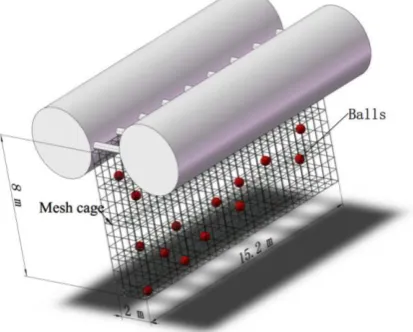
two 4 m diameter × 15.2 m long cylinders and nine 0.4 diameter × 2 m long cylinders. These cylinders also are made of reinforced concrete. In order to achieve wave energy dissipation over a wider range of wave frequency, Model 4 has a mesh cage (15.2 m long, 2 m wide and 8 m high) which is designed to hang below the main structure ( the same size with Model 3). This flexible structure can disturb particle orbit and reduce the cost. In addition, 1200 rubber hollow balls of 0.4 m diameter are put into the mesh cage to enhance the wave energy dissipation. The density of the balls is similar to water so they can freely move.
Fig. 1 Details of the Model 1: the single-box floating breakwater
Fig. 2 Details of the Model 2: the porous floating breakwater
[image:4.595.202.394.194.281.2] [image:4.595.94.488.315.426.2] [image:4.595.196.403.600.766.2]Fig. 4 Details of the Model 4: the cylindrical double pontoon floating breakwater with both the mesh cage and the balls
2.2 Experimental setup and data acquisition
The experiments are conducted in a two dimensional wave flume (45-m long, 0.8-m wide, and 1.2 m deep) located at Jiangsu University of Science of Technology. The glass-walled wave flume was equipped with a piston type wave maker capable of generating incident waves, and the downstream end of the wave flume was installed with a innovative wave absorption system which combines the advantages and design features of armour blocks, inclined and vertical porous plates, so that the remnant waves can be effectively suppressed.
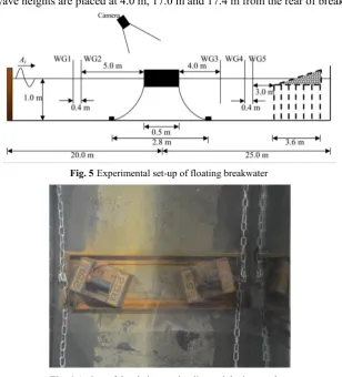
Fig. 5 shows a sketch of the experimental setup. The floating breakwater is restrained in its equilibrium position by a four-slack-line mooring system. Each chain mooring is fastened to a iron anchor which are not moved by the breakwaters during conducting experiments, as shown in Fig. 6. The mooring line is made of stainless steel and had a length of 1.6 m with a line density of 0.63 kg/m. Two load cells (LCs) are used to measure the restraining forces of seaward and the leeward mooring lines, respectively. A non-contact optical tracking system produced by Qualysis is used to capture the six-degree-of-freedom motions of the floating breakwaters. In order to measure accurately the evolution of waves, 5 wave gauges (WGs) are arranged at the centerline of the flume. Note that two gauges for decomposing incident and reflected waves are installed at the position of 5.0 m and 5.4 from the front of breakwaters, respectively. Another three gauges measuring the transmitted wave heights are placed at 4.0 m, 17.0 m and 17.4 m from the rear of breakwaters.
Fig. 5Experimental set-up of floating breakwater
Fig. 6A view of the chain mooring line and the iron anchor 2.3 Experimental model scales and conditions
[image:5.595.145.454.376.717.2]target geometry scale factor in this study is 1:20. Thus, the scale for wave height is 1:20 and the scale for wave period is 1:4.47. The prototype water depth is fixed at 20 m, and wave period ranges from 4.47 s to 20.57 s, which is within the bulk range of long waves. For regular wave, two prototype wave heights of 2.0 m and 3.0 m are selected. According to the experimental model scales, the experimental water depth is 1.0 m; the experimental wave periods ranges from 1 s to 4.6 s; the experimental wave heights are 0.1 m and 0.15 m. In order to investigate the wave protection effect of the floating breakwaters in long wave regime, four models are designed according to the geometrical and mass similarities. Main parameters of these models are listed in Table 1 and photos are shown in Figs. 7-10. The natural periods in sway, heave and roll direction for four models as determined from the decay test is summarized in Table 2.
Table 1 Principal details of the floating breakwater models
Length (mm)
Width (mm)
Height (mm)
Draught (mm)
Gravity center above bottom (mm)
Model 1 760 500 200 100 71
Model 2 760 500 200 100 69
Model 3 760 500 200 100 100
[image:6.595.106.492.368.745.2]Model 4 760 500 510 100 400
Table 2 Natural periods in sway, heave and roll direction for four models
Sway Heave Roll
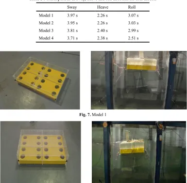
Model 1 3.97 s 2.26 s 3.07 s Model 2 3.95 s 2.26 s 3.03 s Model 3 3.81 s 2.40 s 2.99 s Model 4 3.71 s 2.38 s 2.51 s
Fig. 7. Model 1
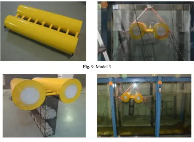
Fig. 9. Model 3
Fig. 10. Model 4 2.4 Data analysis
The incident (Ai) and reflected (Ar) wave amplitudes are determined using Goda's method [25]
based on the experimental data recorded by suitable pair of wave gauges i.e. WG 1 and WG 2 in front of the breakwater. The transmitted (At) wave amplitudes are directly obtained by analyzing the
experimental data recorded by the wave gauge WG 3 in the leeward sider of the breakwater. The reflected wave amplitudes from the designed absorbing system are denoted by Ara, which can be
separated from the data by the wave gauges WG 4 and WG 5. The reflection coefficient (Kr),
transmission coefficient (Kt), and reflection coefficient (Kra) of the absorbing system are defined as Ar/Ai, At/Ai and Ara/Ai. The energy dissipation coefficient (Kd) is defined as the ratio between the
dissipated energy and the energy if incident waves. The dimensionless coefficients are related as [9]:
2 2 2
1
r t d ra
K
+
K
+
K
= +
K
(1)Here, Kd denotes the contributions from the vortex generated by the edges of the structure,
viscous dissipation by porous floating breakwater or mesh cage and balls, the motion responses of floating breakwaters, wave breaking at seaward of floating breakwaters and wave overtopping. The amplitudes of sway (Asway), heave (Aheave), and roll (Aroll) responses are defined as the
oscillation amplitude relative to the mean position of the floating breakwaters in waves. For later discussion, the sway, heave and roll response amplitude operators (RAOs) are defined as sway RAO= Asway/ Ai, heave RAO= Aheave/ Ai and roll RAO= Aroll/Ai, respectively.
Meanwhile, Fs and Fl are defined as the peak values of the forces acting upon the seaward and
the leeward mooring lines, respectively.
3. Results and discussions
3.1 Reflection coefficient
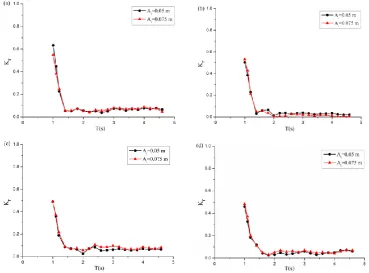
Fig. 11a-d depicts the variations of reflection coefficient Kr for four models as functions of wave
period T with two incident wave amplitude Ai=0.05 m and 0.075 m. The data in these figures shows
that the total reflection coefficient of each model decreases initially with increasing wave period which is consistent with that obtained by Koraim and Rageh [19], and then almost remains the same after the value T=1.25 s. This means that long waves are almost entirely transmitted over all types of floating breakwaters and are very difficult to be suppressed. For all two incident wave amplitude, the reflection coefficients all have their minimum values at wave period T>1.7 s for models, and the minimum reflection coefficients are about 0.035 for Model 1, 0.01 for Model 2, 0.045 for Model 3 and 0.03 for Model 4. These non-zero reflection coefficient in our experiments may be the results of the radiated waves induced by the motions of the floating breakwaters. It is concluded that the porous plates of Model 3 and mesh cage with balls of Model 4 can destruct water particle orbital motions and provide more viscous damping, which result in weaker reflections in long regime. In addition, the wave reflection coefficient of all models at each incident wave amplitude followed the similar trends throughout the range of the tested wave periods. For Model 1, 3 and 4, the wave reflection increases slightly with increasing incident wave amplitude, which is the opposite for Model 2. This occurs because, for a fixed wave period, the higher waves for Model 1, 3 and 4 increases the motions of the structure, and the intense heave and roll motion can increase the seaward area of breakwater, which also results in stronger reflection. However, for Model 2, owing to porous plates of the breakwater, higher waves will lead more waves to flow into the top part of the model. The added water weight make Model 2 sink below the water line, and thus more waves can be transmitted over Model 2.
[image:8.595.116.486.420.693.2]
Fig. 11. Variations of reflection coefficient Kr versus waver period T for incident wave amplitude Ai 0.05 and 0.075 m. (a) Model 1, (b) Model 2, (c) Model 3, (d) Model 4.
3.2 Transmission coefficient
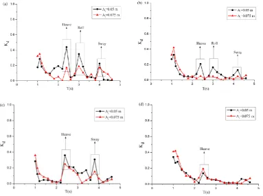
12a-d shows the measured transmission coefficient versus the wave period and incident wave amplitude. The data reveals that the total transmission coefficient of each model increases rapidly until it reaches its maximum value at wave period T= 2 s and then has some turning points in long wave regime. In theory, the breakwaters are almost transparent to very long waves, and the transmission coefficient approaches one when wave period T>2 s. Actually, however, the wave transmission coefficients abruptly decrease at some turning points (around 2.4 s, 3.0 s and 3.9 s in this set of experiments), especially for Model 1 and 3. In addition, The wave periods corresponding to turning points are closed to the heave, roll and sway natural period of floating breakwaters, respectively. This can be explained by the resonant motions of floating breakwaters. When incident wave period is closed to the natural period of floating breakwaters, the energy transfer from the incident wave to motion of structure will increase, and the transmitted wave energy will be reduced by the same condition, resulting in a sudden drop transmission coefficient (e.g. when Ai=0.05 m, for
Model 1, Kt of three turning points decrease 18.4%, 16.5% and 11.2%; for Model 2, Kt of three
turning points decrease 7.3%, 6.2% and 3.1%; for Model 3, Kt of two turning points decrease 20.2%
and 14.4%; for Model 3, Kt of one turning point decrease 7.07%). Thus, for all models, the turning
point phenomenon corresponding to heave resonant response is most evident. But the reflected wave energy in long regime is not much affected by the resonant motions, which can be found in Fig. 11. It is interesting to note that the transmission coefficient at these period turning points for Model 4 is larger than that for Model 3. For instance, the Model 4 is capable of increasing the turning point value by nearly 15% and 5% at T=2.4 s with Ai= 0.05 m and 0.075 m, respectively. This is because
the mesh cage containing suspending balls can induce additional damping and inertia to lead the motion response reduction of breakwater. That is, compared with Model 4, more wave energy is transformed into kinetic energy of the Model 3. By comparisons between Model 1 and Model 2, it is also be found that the turning point phenomenon of Model 1 is more evident than that of Model 2 for all incident wave amplitudes, which is owing to the viscous energy dissipation of porous plates. For all types of floating breakwaters, increasing incident wave amplitude enhance the wave attenuation effectiveness when structure is exposed to shorter period waves (T<1.5 s). This implies that the shorter and higher waves tend to have more intense interactions with the floating structure-the same trend has also been found by Teh and Ismail [26]. However, in long wave regime (T>1.5 s), the transmission coefficient increases with increasing incident wave amplitude for Model 1, 2 and 3, and the turning phenomenon of Model 2 is not outstanding when Ai=0.075 m owing to the
permeability of this porous floating breakwater. The transmission coefficient of Model 4 is not very sensitive to the change of incident wave amplitude, which further indicates that the use of the cage and the balls can significantly improve the hydrodynamic behavior of the floating breakwater.
Fig. 12. Variations of transmission coefficient Kt versus waver period T for incident wave amplitude Ai 0.05 and 0.075 m. (a) Model 1, (b) Model 2, (c) Model 3, (d) Model 4.
3.3 Energy dissipation coefficient
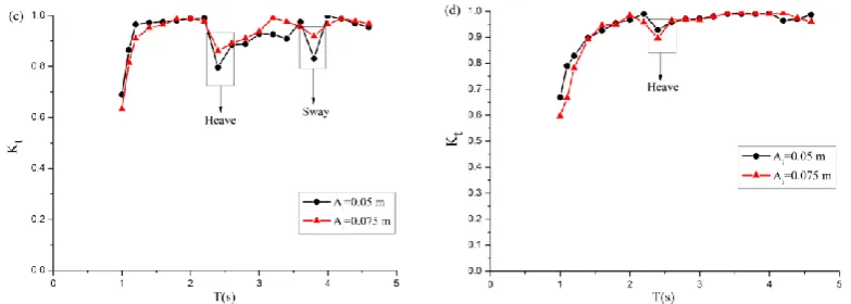
Fig. 13a-d presents the relationship between the wave energy dissipation coefficient Kd
calculated by Eq. (1) and the wave period T for the four models when incident wave amplitude
Ai=0.05 m and 0.075 m. The figure shows that the four models are highly dissipative when exposed
to moderate-length incident wave (T=1.1 s), and the Model 2 and Model 4 dissipate more wave energy as compared with Model 1 and 3. For all incident wave amplitudes, the energy dissipation coefficient in long wave regime oscillates between its maximum and minimum values as the wave period changes. As a result, the maximum energy dissipation coefficients corresponding to three turning points for Model 1 are about 0.47, 0.4, and 0.29 at Ai=0.05 m, respectively; three turning
point values for Model 2 reach about 0.21, 0.18 and 0.15 at Ai=0.05 m; two turning point values for
Model 3 reach about 0.39, and 0.35 at Ai=0.05 m; only one turning point value for Model 3 reaches
about 0.21 at Ai=0.075 m. Comparing the four models, the traditional pontoon-type floating
breakwaters are more efficient and viable energy dissipater in long regime (e.g. Kd of Model 1 at
three turning points increases 55.3%, 55.0% and 48.3% compared with Model 2 when Ai=0.05 m; Kd of Model 3 at first turning point increases 46.1% compared with Model 4 when Ai=0.05 m). In
addition, the maximum energy dissipation occur near the heave natural period. We remark that for very long waves, installing the porous plates and mesh cage with balls do not seem to boost the dissipative performance of the floating breakwater considerably.
[image:11.595.109.493.76.362.2]
Fig. 13. Variations of energy dissipation coefficient Kd versus waver period T for incident wave amplitude Ai 0.05 and 0.075 m. (a) Model 1, (b) Model 2, (c) Model 3, (d) Model 4.
3.4 Motion responses
transmission and dissipation. It is also seen from these figures that the use of porous materials can weaken the turning point phenomenon (e.g. for all incident wave amplitudes, the sway, heave and roll motion RAOs at turning periods of Model 2 decrease 17.6%, 15.3% and 16.1 % compared with that of Model 1, respectively; turning point motion RAOs of Model 3 are reduced by 42.8 %, 11.1% and 41.6 % when installing mesh cage with balls under the structure, respectively) owing to viscous damping effects and permeability.
For the two incident wave amplitudes in our experiments, the incident wave amplitude do not have a significant effect on the trends of the motion RAO varying with wave period T. The higher waves slightly amplify the motions of four models in moderate-length incident wave regime (T<1.8 s) and vice versa when T<2.6 s, which is similar to that of the energy dissipation. Overall, the heave and roll motion RAO of four models are not very sensitive to the change of incident wave amplitude. This implies that the heave and roll motion responses of floating breakwaters increase approximately linearly with incident wave amplitude.
[image:12.595.111.485.289.581.2]
Fig. 14. Variations of sway RAO versus waver period T for incident wave amplitude Ai=0.05 and 0.075 m. (a) Model 1, (b) Model 2, (c) Model 3, (d) Model 4.
Fig. 15. Variations of heave RAO versus waver period T for incident wave amplitude Ai=0.05 and 0.075 m. (a) Model 1, (b) Model 2, (c) Model 3, (d) Model 4.
Fig. 16. Variations of roll RAO versus waver period T for incident wave amplitude Ai=0.05 and 0.075 m. (a) Model 1, (b) Model 2, (c) Model 3, (d) Model 4.
3.4 Mooring forces
The capability of mooring system of the floating breakwaters is also a critical design factor and is determined by the motion responses of structure. In the present study, the restraint effects of the mooring lines are evaluated by the tensions of the seaward and leeward lines. Figs. 17 and 18 give the variations of the mooring forces with the wave period and incident wave amplitude for four models. The figures show that both Fs and Fl initially decrease with increasing the wave period, and
then increase roughly when wave period T >2 s. The effect of the incident wave amplitudes can be clearly observed from the larger mooring forces of Model 1, 2 and 3 produced by higher the incident wave amplitude, especially in long wave regime with other test conditions unchanged (e.g. the maximum Fs of Model 1, 2 and 3 increase 30.5%, 20.7% and 62.0% for Ai=0.075 m compared with
[image:13.595.101.495.246.536.2]to increase the slowly varying wave drift forces on the body wet surfaces. As a result, Fs of Model
4 is larger than that of other three models when T< 1.8 s, which can be explained by the same reason with the sway motion. In the extremely long wave regime, Fs and Fl of Model 4 are smallest as
compared with other models, and stay nearly unchanged for non-resonant periods because of the damping effect of mesh cage with balls. In this particular case, mooring forces of Model 2 are smaller than that of Model 1, especially for long waves. This mainly includes two reasons. First, the porous material of Model 2 can dissipate some wave energy by viscous effects and breaking waves to lead the motion reduction of the structure. Second, the sinking of Model 2 in long and high wave regime causes the mooring lines to slack.
As can be observed, the trend of the mooring forces for four models is not monotonic in the whole wave period range, and there are some turning points appear near the natural periods of floating breakwaters, which matches the observation that the motion responses increase at the natural periods of structure. In addition, the installation of porous plates and mesh cage will reduce the resonant responses and mooring forces.
[image:14.595.103.496.298.598.2]
[image:15.595.99.497.78.385.2]
Fig. 18. Variations of leeward mooring force Fl versus waver period T and incident wave amplitude Ai. (a) Model 1, (b) Model 2, (c) Model 3, (d) Model 4.
4. Conclusions
In this paper, four types of floating breakwaters are introduced based on the single or double pontoon configuration. A series of experiments including wave surface elevations, motion responses and mooring forces are conducted to study the hydrodynamic performance of these breakwaters in long wave regime. The main findings from this study are the following:
1) The transmission and energy dissipation coefficients for four models have some turning points corresponding to the natural period of breakwaters in long wave regime, while the turning point phenomenon of the reflection coefficient is not outstanding.
2) With the use of porous plates and mesh cage with containing suspending balls, the interesting turning point phenomenon of the floating breakwaters to long regular waves is mitigated by the water mass inside the top part of porous model and the increase in damping and inertia.
3) The mesh cage can increase the sway motion and seaward mooring tension of breakwater for a moderate-length incident wave owing to additional wave forces on the mesh cage. However, for extremely long incident waves, the damping contribution from porous plates or mesh cage with balls can reduce the motion responses and mooring loads.
4) Resonant responses can also be observed in the motions and mooring tension of breakwaters, and enhance energy exchange between the wave energy and the kinetic energy of the structure. Therefore, the wave transmission can be reduced near the natural period of structure according to energy conservation.
wave regime is not very sensitive to the incident wave amplitude.
Through the experimental studies, it can be concluded that all four types of floating breakwaters have the turning point phenomenon for long wave scattering. Furthermore, the viscous damping induced by porous plates or mesh cage with balls is the major contributor to suppress resonant responses and mooring forces. This can be extended straightforwardly to irregular wave cases in a future study.
5. Acknowledgment
The authors are grateful to the National Science Foundation of china (Grant No. 51579122) and Natural Science Found of Jiangsu province (BK20160556) for supporting this work.
References
[1] Hales LZ. Floating breakwaters: state-of-the-art literature review, Technical Report no. 81-1, 1981. US army Engineer Waterways Experiment Station. Vicksburg, Mississippi, USA.
[2] McCartney BL. Floating breakwater design. J. Waterw. Port Coastal Ocean Eng. 1985; 123(4): 172-179. [3] Abul-Azm A, Gesraha M. Approximation to the hydrodynamics of floating pontoons under oblique waves. Ocean
Eng. 2000; 27(4): 365-384.
[4] Gesraha MR. An eigenfunction expansion solution for extremely flexible floating pontoons in oblique waves. Appl. Ocean Res. 2004; 26(5): 171-182.
[5] Drimer N, Agnon Y, Stiassnie M. A simplified analytical model for a floating breakwater in water of finite depth. Appl. Ocean Res. 1992; 14(1): 33-41.
[6] Diamantoulaki I, Angelides DC, Manolis GD. Performance of pile-restrained flexible floating breakwaters. Appl. Ocean Res. 2008; 30(4): 243-255.
[7] Koutandos E, Karambas TV, Koutitas C. Floating breakwater response to waves action using a Boussinesq model coupled coupled with a 2DV elliptic solver. J. Waterw. Port Coast. Ocean Eng. 2004; 130(5): 243-255. [8] Lee J, Cho W. Effects of mean wave drift force on mooring tension and performance of a moored floating
breakwater. KSCE J. Civ. Eng. 2002; 6(2):193-201.
[9] He F, Huang ZH, Adrian W-KL. Hydrodynamic performance of a rectangular floating breakwater with and without pneumatic chambers: An experimental study. Ocean Eng. 2012; 51: 16-27.
[10] He F, Huang ZH, Adrian W-KL. An experimental study of a floating breakwater with asymmetric pneumatic chambers for wave energy extraction. Appl. Energy 2013; 106: 222-231.
[11] Ning DZ, Zhao XL, Goteman M, Kang HG. Hydrodynamic performance of a pile-restrained WEC-type floating breakwater: An experimental study. Renewable Energy 2016; 95: 531-541.
[12] Williams AN, Abul-Azm AG. Dual pontoon floating breakwater. Ocean Eng. 1997; 24(5): 465-478. [13] Weng WK, Chou CR. Analysis of response of floating breakwater. China Ocean Eng. 2007; 21(1): 91-104. [14] Ji CY, Chen X, Cui J, Yuan ZM, Incecik A. Experimental study on configuration optimization of floating
breakwaters. Ocean Eng. 2016; 117: 302-310.
[15] Dong GH, Zheng YN, Li YC, Teng B, Guan CT, Lin DF. Experiments on wave transmission coefficients of floating breakwaters. Ocean Eng. 2008, 35: 931-938.
[16] Tang HJ, H CC, C WM. Dynamics of dual pontoon floating structure for cage aquaculture in a two-dimensional numerical wave tank. Journal of Fluids and Structures 2011; 27: 918-936.
[17] Mizutani N, Rahman A. Performance of submerged floating breakwater supported by perforated plates under wave action and its dynamics. In: Proceedings of Civil Engineering in the Ocean. ASCE, Baltimore, 2006: 329-341.
breakwater. China Ocean Eng. 2013; 28(3): 349-362.
[20] Cho IH, Kim MH. Wave absorbing system using inclined perforated plates. J. Fluid Mech. 2008; 608: 1-20. [21] Cho IH, Kim MH. Transmission of oblique incident waves by a submerged horizontal porous plate . Ocean Eng.
2013; 61: 56-65.
[22] Cho IH. Transmission coefficients of a floating rectangular breakwater with porous side plates. International Journal of Naval Architecture and Ocean Engineering 2016; 8: 53-65.
[23] Cheng Y, Ji CY, Zhai GJ, Gaidai O. Hydroelastic analysis of oblique irregular waves with a pontoon-type VLFS edged with dual inclined perforated plates. Mar. Struct. 2016; 49: 31-57.
[24] Ji CY, Chen X, Cui J, Yuan ZM, Incecik A. Experimental study of a new type of floating breakwater. Ocean Eng. 2015; 105: 295-303.
[25] Goda Y, Suzuki Y. Estimation of incident and reflected waves in random wave experiments. In: Proceedings of the 15th international conference on coastal engineering ASCE, 1976: 828-845.