Dynamic Performance of a Low Voltage MicroGrid
with Droop Controlled Distributed Generation
Theofilos A. Papadopoulos
Panagiotis N. Papadopoulos
Grigoris K. Papagiannis
Power Systems Laboratory, Dept. of Electrical & Computer Engineering
Aristotle University of Thessaloniki, AUTh Thessaloniki, Greece
Paul Crolla
Andrew J. Roscoe
Graeme M. Burt
Institute for Energy and Environment, Department of Electronic and Electrical Engineering
University of Strathclyde Glasgow, UK [email protected]
Abstract—Microgrids are small-scale autonomous networks designed to supply electrical energy and heat. From the operational point of view, microgrids are active distribution networks, facilitating the integration of distributed generation units. Major technical issues in this concept are the system stability and protection coordination which are significantly influenced by the high penetration of inverter-interfaced distributed energy sources. These units usually adopt the frequency-active power and voltage-reactive power droop control strategy to participate in the load sharing of the microgrid. Scope of the paper is to investigate the dynamic performance of a low voltage laboratory-scale microgrid system, using experimental results. Several small disturbance test cases are conducted and the investigations focus on the influence of the droop controlled distributed generation sources.
Index Terms--Distributed power generation, droop control, microgrid, transient stability.
I. INTRODUCTION
Driven by the global requirements for reliable, efficient and environmentally friendly electric power, the conventional power grid is gradually transformed to a modern one with enhanced functions, commonly described by the term "Smart Grids". Smart Grids are intelligently controlled, active, networks that facilitate the integration of distributed generation (DG) into the power system [1].
The types of DG units differ in type and size, depending on the energy source used [1] with significant differences in performance, power capacities and generation characteristics. Diesel and asynchronous generators are directly ac coupled to the grid, while others, either static or rotating are connected through power electronic converters, allowing great flexibility and controllability [1], [2].
In this context, several techniques and power management strategies have been proposed in order to maximize the DG penetration and the utilization of the power system. The most important are active management, virtual power plants and
microgrids [1]. The development of microgrids is a promising philosophy for the electric energy industry, it offers several advantages; the most significant being the reduction of electrical losses through closer load/ source proximity, the improvement of power quality, the reduction of greenhouse gas emissions and the increase of the reliability of the power system[2].
In microgrids two control strategies of the DG units are usually adopted, peer-to-peer and master-slave control [1] - [3]. In the first case each DG unit has an equivalent status and can operate autonomously without any communication system by using real and reactive droop-based local controllers [3]. However, high penetration of droop controlled DG units in microgrids creates a number of issues, including the stability and the protection coordination of the microgrid when small or large disturbances occur, such as switching events and faults [5], [6].
Therefore, several research studies focus on the dynamic security assessment (DSA) and the evaluation of the transient performance of microgrids in order to improve the dynamic performance and increase the stability of the system [7] using mainly standard simulation tools and computational techniques [5] - [10]. Only recently some laboratory-scale microgrid systems have been developed [11] - [14], providing a reliable verification platform and valuable tool for practical experimentation and research [11].
The scope of the paper is to investigate the dynamic performance of a low voltage (LV) microgrid, using experimental results from a 100 kVA laboratory-scale microgrid system, available at Strathclyde University in Glasgow, U.K. [14]. The analysis focuses on cases that the microgrid system is subjected to small disturbances, caused from changes in the operational state of the loads. Special emphasis is given on the influence of the droop controlled DG unit penetration on the dynamic performance of the microgrid system as well on the performance of each DG unit
individually. The microgrid is examined either in grid-connected or islanded mode of operation.
II. LVLABORATORY-SCALE MICROGRID SYSTEM
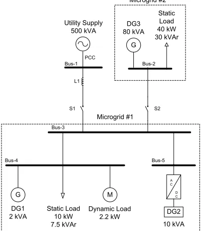
The laboratory-scale microgrid configuration is presented in Fig. 1. The three-phase, 400 V, 100-kVA microgrid can be split into two sub-microgrids, namely microgrid #1 and #2 and can operate both in grid-connected and islanded mode using the interconnection switch S1. A 1.21 per-unit (p.u.) inductance (L1) is included in the network to emulate stiff/weak network topologies.
DG1 2 kVA
Static Load 10 kW 7.5 kVAr
DG2
A C
D C
G M
Microgrid #1
10 kVA
Bus-4 Bus-5
G
Bus-3
DG3 80 kVA
Static Load 40 kW 30 kVAr Utility Supply
500 kVA
Bus-1 Bus-2
Microgrid #2
Dynamic Load 2.2 kW
L1
S2 PCC
[image:2.612.74.276.198.431.2]S1
Figure 1. LV microgrid laboratory system configuration.
A. Microgrid #1
Microgrid #1 consists of Bus-3, Bus-4 and Bus-5, DG units DG1 and DG2, a static load bank and an induction motor.
DG1 is a synchronous generator 2 kVA, 50-Hz, 400 V, 1500 rpm with power factor 0.85, lagging directly ac connected to the microgrid. The prime mover is coupled to a DC motor, which is driven by a variable frequency drive. DG1 can emulate the behavior of a diesel genset or a small CHP turbine by tuning properly the drive frequency properties. DG2 is an inverter interfaced generation unit of 10 kVA nominal power with power factor 0.8, lagging. DG units balance the power and provide frequency and voltage support in the microgrid using frequency – active power (f – P) and voltage – reactive power (V – Q) droop control. The f – P and
V – Q droop characteristics of the two DG units are presented
in Figs. 2a and 2b, respectively, showing that the inverter interfaced unit has a larger share on reactive power variations than the synchronous generator. The droop control strategy is adopted in both grid-connected and islanded mode of operation for the two DG units.
The static load bank #1 is composed by a 64-step variable resistance and inductance with nominal power 10 kW and
7.5 kVAr, respectively. The 2.2 kW, 50-Hz, 400 V, 0.87 lagging, induction motor is used as a dynamic load model and is also driven by a variable frequency drive.
B. Microgrid #2
Microgrid #2 consists of DG3, which is a 80 kVA, 50-Hz, 400 V and 1500 rpm synchronous generator, driven by a software model emulating a slow prime mover, such as a steam-turbine [14]. The 80 kVA generator is controlled as a shared generator together with the rest DG units in a peer-to-peer operation mode. The microgrid system can operate also as a power island, when switch S1 is open and S2 is closed, allowing microgrid #2 to connect to the microgrid system. In island mode each DG unit is controlled based on the local frequency and voltage, using the corresponding f – P
and V – Q droop characteristics. In this scenario DG3 has the
main load sharing part compared to DG1 and DG2, due to its higher power capacity.
Finally, the nominal active and reactive power of the 256-step static load bank #2 is 40 kW and 30 kVAr, respectively.
0 f
f
(a) (b)
f pu
DG1 & DG2
DG1
DG2
0
p p p pu q0 q q pu
v pu
0
v
[image:2.612.318.557.311.440.2]v
Figure 2. Droop characteristics of DG1 and DG2 for a) real power (f - P) and b) reactive power (V - Q)
III. LOAD SHARING
The objective of this section is to investigate the dynamic performance and the participation in the load share of each DG unit, while microgrid # 1 operates in grid-connected and in islanded mode.
A. Grid-connected mode
The grid-connected mode of operation is examined, while microgrid #1 is connected to a “stiff” and also to a “weak” utility supply grid, using the 1.21 p.u. inductor L1. In Figs. 3 and 4 the active and reactive power share for the stiff grid are presented, while in Figs. 5 and 6, the corresponding responses are shown for the weak grid case. In both scenarios the total power of the static and the dynamic load is 7.1 kW and 3.8 kVAr, respectively; while a 30 % increase in the static load #1 is applied.
Therefore, any change in the load demand in both cases is accommodated by the utility supply, which provides 72 % and 78 % of the microgrid active power demand in the steady-states prior to and after the disturbance, respectively.
In the transient period subsequent to the disturbance for the case of the weak grid in Fig. 5, Bus-3 active power and frequency present an oscillation, due to the dynamic response of DG1. The oscillation in DG1 is due to the effect of the synchronous generator electromechanical mode, with a frequency of approximately 3 Hz, being the dominating system mode [5], [6]. The damping oscillation in DG2 response follows the Bus-3 frequency oscillation, due to the corresponding droop characteristic. This oscillatory nature of the DG dynamic response appears only in weak grid topologies, e.g. a connection via long interconnection lines [15]. This is attributed to the performance of DG1 during the load change, which reduces its speed by releasing kinetic energy [6], [15] causing a variation in the network frequency transient response, as shown in Fig. 5b.
0 0.1 0.2 0.3 0.4 0.5 0.6 0.7 0.8 0.9 1 0
2000 4000 6000 8000 10000 12000
time (sec)
W
[image:3.612.312.560.177.339.2]Bus-3 DG1 DG2 Load
Figure 3. DG active power share for the stiff grid.
0 0.1 0.2 0.3 0.4 0.5 0.6 0.7 0.8 0.9 1 0
2000 4000 6000
time (sec)
VAr
a) Reactive power share
Bus-3 DG1 DG2 Load
0 0.1 0.2 0.3 0.4 0.5 0.6 0.7 0.8 0.9 1 404.5
405 405.5 406
time (sec)
V
b) Bus-3 voltage
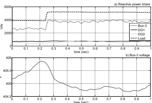
Figure 4. DG a) reactive power share for the stiff grid and b) Bus-3 voltage.
In the case of the stiff grid the voltage variation is less than 1%, thus the DG reactive power output remains practically constant prior to and after the disturbance. However, in the weak grid topology a voltage drop of
approximately 4 V is recorded at Bus-3, due to the influence of L1. Therefore, both DG units adjust their reactive power output, contributing to the microgrid reactive power compensation [5], according to the V – Q droop characteristics with DG2 having a larger share in the reactive power demand. Initially 68 % of the reactive power is supplied by the grid, while after the load change, 60 % is provided, due to the participation of the DG units in the reactive power share.
0 0.1 0.2 0.3 0.4 0.5 0.6 0.7 0.8 0.9 1 0
2000 4000 6000 8000 10000
time (sec)
W
a) Active power share
Bus-3 DG1 DG2
0 0.1 0.2 0.3 0.4 0.5 0.6 0.7 0.8 0.9 1 49.94
49.96 49.98 50 50.02
time (sec)
Hz
[image:3.612.52.299.296.458.2]b) Bus-3 frequency
Figure 5. DG a) active power share for weak grid and b) bus frequency.
0 0.1 0.2 0.3 0.4 0.5 0.6 0.7 0.8 0.9 1 0
1000 2000 3000 4000
time (sec)
VAr
a) Reactive power share
Bus-3 DG1 DG2
0 0.1 0.2 0.3 0.4 0.5 0.6 0.7 0.8 0.9 1 396
398 400 402 404
time (sec)
V
[image:3.612.315.557.371.529.2]b) Bus-3 voltage
Figure 6. DG a) reactive power share for the weak grid and b) Bus-3 voltage.
B. Islanded mode
[image:3.612.54.297.487.652.2]power flow in the island by adjusting its power output, since the DG3 active and reactive responses practically follow the corresponding of Bus-3, as shown in Figs. 7b and 8b.
0 1 2 3 4 5 6
500 1000 1500 2000
time (sec)
W
a) Active Power Share - Microgrid #1
DG1 DG2
0 1 2 3 4 5 6
2 2.5
x 104
time (sec)
W
b) Active Power Share - DG3 & Bus-3
0 1 2 3 4 5 60
5000 10000
DG3 Bus-3
0 1 2 3 4 5 6
49.8 49.9 50 50.1
time (sec)
Hz
c) Bus-3 frequency
W2.5
x 104
5000 10000
[image:4.612.56.291.103.263.2]0
Figure 7. Active power share for a) microgrid #1 and b) microgrid #1 c) Bus-3 frequency.
0 1 2 3 4 5 6
500 1000 1500 2000
time (sec)
VAr
a) Reactive Power Share - Microgrid #1
DG1 DG2
0 1 2 3 4 5 6
1 1.2 1.4x 10
4
time (sec)
VAr
b) Reactive Power Share - DG3 & Bus-3
0 1 2 3 4 5 6-2000
0 2000 DG3 Bus-3
0 1 2 3 4 5 6
390 395 400
time (sec)
V
c) Bus-3 voltage
1.4 x 10
4
1.2
V
A
r
1.0 1.0
0 2000
[image:4.612.316.557.239.399.2]-2000
Figure 8. Reactive power share for a) microgrid #1 and b) microgrid #1 c) Bus-3 frequency.
The duration of the transient period of the disturbance is about 3 s and is significantly longer compared to the grid-connected case. In this scenario a single control area power system operation can be assumed[15]. The oscillatory damped response of frequency is due to the release of DG3 kinetic energy, thus reducing its speed and the system frequency, presented in Fig. 7c. The oscillations of DG1 and DG2 active power responses are due to the frequency variation at Bus-3, according to the corresponding f – P droop characteristics, showing that the influence of the drooped controlled DG2 on the active power response is significant. The oscillation frequency is 1.5 Hz [6], due to the greater mass of DG3, compared to DG1, which determines the 3 Hz oscillation in the grid-connected mode. The peak in the reactive power dynamic responses of the two generators DG1 and DG3 are due to the influence of the AVR.
IV. INFLUENCE OF DROOP CONTROLLED UNITS
The influence of the droop controlled units penetration on
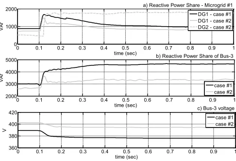
the dynamic responses of a microgrid is investigated, in the case of 50 % load increase. The weak grid-connected and islanded microgrid configurations are examined, with DG2 producing 0 kW in case #1 and in 1 kW case #2 with nominal power factor.
A. Grid-connected mode
In Figs. 9 and 10 the active and reactive power share of the DG units are presented, respectively, as well as the Bus-3 frequency and voltage responses. It is shown that the influence of the increased penetration of the droop controlled DG2 on the active power and frequency dynamic response of the microgrid is not significant, since the dominating electromechanical mode is slightly affected by the f – P droop of the inverter based DG units [6].
0 0.1 0.2 0.3 0.4 0.5 0.6 0.7 0.8 0.9 1 0
1000 2000 3000
time (sec)
W
a) Active Power Share - Microgrid #1 DG1 - case #1 DG1 - case #2 DG2 - case #2
0 0.1 0.2 0.3 0.4 0.5 0.6 0.7 0.8 0.9 1 0.5
1 1.5x 10
4
time (sec)
W
b) Active Power Share of Bus-3 case #1 case #2
0 0.1 0.2 0.3 0.4 0.5 0.6 0.7 0.8 0.9 1 49.8
49.9 50 50.1
time (sec)
Hz
c) Bus-3 frequency
[image:4.612.57.294.302.459.2]case #1 case #2
Figure 9. Active power share for a) microgrid #1 and b) Bus-3 c) Bus-3 frequency.
0 0.1 0.2 0.3 0.4 0.5 0.6 0.7 0.8 0.9 1 0
1000 2000
time (sec)
VAr
a) Reactive Power Share - Microgrid #1 DG1 - case #1 DG1 - case #2 DG2 - case #2
0 0.1 0.2 0.3 0.4 0.5 0.6 0.7 0.8 0.9 1 2000
3000 4000 5000
time (sec)
VAr
b) Reactive Power Share of Bus-3
case #1 case #2
0 0.1 0.2 0.3 0.4 0.5 0.6 0.7 0.8 0.9 1 360
380 400 420
time (sec)
V
c) Bus-3 voltage case #1 case #2
Figure 10. Reactive power share for a) microgrid #1 and b) Bus-3 c) Bus-3 voltage.
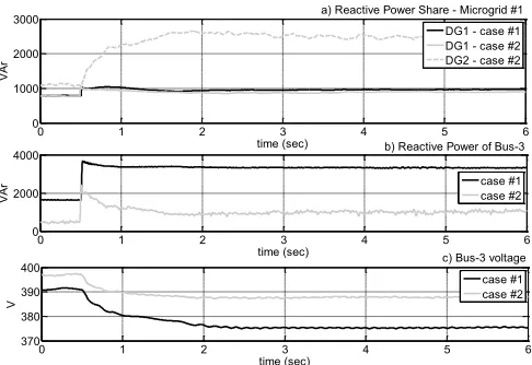
[image:4.612.315.558.436.602.2]B. Islanded mode
In the islanded mode of operation the active power dynamic response of microgrid #1 is significantly affected by DG2. DG2 has no inertia, thus it is affected by the system frequency variation, according to the f – P droop characteristics. On the contrary in case #1, there is no ripple in the active power dynamic response at Bus-3, since DG1 with inertiapresents low sensitivity to the system variations, having an insignificant effect on the total active power response.
Considering the reactive power in case #2 the dynamic response of DG1 is less severe than in case #1. This is attributed to the lower voltage drop at Bus-3, due to the additional reactive power offered by DG2.
0 1 2 3 4 5 6
0 1000 2000 3000
time (sec)
W
a) Active Power Share - Microgrid #1 DG1 - case #1
DG1 - case #2 DG2 - case #2
0 1 2 3 4 5 6
0 5000 10000
time (sec)
W
b) Active Power of Bus-3
case #1 case #2
0 1 2 3 4 5 6
49.5 50 50.5
time (sec)
Hz
c) Bus-3 Frequency case #1 case #2
Figure 11. Active power share for a) microgrid #1 and b) Bus-3 c) Bus-3 frequency.
0 1 2 3 4 5 6
0 1000 2000 3000
time (sec)
VAr
a) Reactive Power Share - Microgrid #1 DG1 - case #1 DG1 - case #2 DG2 - case #2
0 1 2 3 4 5 6
0 2000 4000
time (sec)
VAr
b) Reactive Power of Bus-3
case #1 case #2
0 1 2 3 4 5 6
370 380 390 400
time (sec)
V
c) Bus-3 voltage case #1 case #2
Figure 12. Reactive power share for a) microgrid #1 and b) Bus-3 c) Bus-3 voltage.
V. CONCLUSIONS
In this paper, the dynamic performance of a laboratory scale microgrid is examined with special emphasis on the influence of the droop controlled units. The analysis is implemented, using experimental results.
In grid-connected operation it is shown that transients occur on the mircogrid response only in the case of weak grids, due mainly to the influence of synchronous generators. Inverter interfaced units participate in the examined topology mainly on the reactive power share, according to their droop characteristics.
On the contrary, in the islanded mode of operation, the droop controlled inverter interfaced units influence significantly the dynamic responses of both the active and reactive power of the microgrid, since their behavior depends strongly on the frequency variation and the voltage drop on the microgrid buses.
REFERENCES
[1] N. Jenkins, J.B. Ekanayake, and G. Strbac, Distributed Generation, London: The Institute of Engineering and Technology, 2010.
[2] S. Chowdhury, S. P. Chowdhury, and P. Crossley, Microgrids and Active Distribution Networks, London: The Institute of Engineering and Technology, 2009.
[3] J.A. Pecas Lopes, C. L. Moreira, "Defining control strategies for MicroGrids islanded operation," IEEE Trans. on Power Systems, vol. 21, no.2, pp. 916-924, 2006.
[4] S. Krishnamurthy, T.M. Jahns, R.H. Lasseter, "The operation of diesel gensets in a CERTS microgrid," in Proc. 2008 IEE Power and Energy Society General Meeting - Conversion and Delivery of Electrical Energy in the 21st Century, pp.1-8, 20-24 July 2008.
[5] F. Katirei, and M. R. Iravani, "Power Management Strategies for a Microgrid with Multiple Distributed Generation Units," IEEE Trans. on Power Systems, vol. 21, no.21, pp. 1821-1831, Nov. 2006.
[6] Z. Miao, A. Domijan, L. Fan, “Investigation of Microgrids with Both Inverter Interfaced and Direct AC-Connected Distributed Energy Resources,” IEEE Trans. On Power Delivery, vol. 26, no. 3, July 2011. [7] A. Al-Hinai, K. Sedhisigarchi, and A. Feliachi, "Stability enhancement
of a distribution network comprising a fuel cell and a microturbine," in Proc. 2004 IEEE Power Engineering Society General Meeting, pp. 2156-2161.
[8] A.S. Emhemed, R.M. Tumilty, N.K. Singh, G.M. Burt, and J.R. McDonald, "Analysis of Transient Stability Enhancement of LV-Connected Induction Microgenerators by Using Resistive-Type Fault Current Limiters," IEEE Transactions on Power Systems, vol.25, no.2, pp.885-893, May 2010.
[9] D.J. Lee, L. Wang , "Small-Signal Stability Analysis of an Autonomous Hybrid Renewable Energy Power Generation/Energy Storage System Part I: Time-Domain Simulations," IEEE Transactions on Energy Conversion, vol.23, no.1, pp.311-320, March 2008.
[10] F. Katiraei, M. R. Iravani, and P. W. Lehn, "Micro-Grid Autonomous Operation During and Subsequent to Islanding Process," IEEE Trans. on Power Systems, vol. 20, no. 1, pp. 248-257, Jan. 2005.
[11] B. Zhao, X. Zhang, J. Chen, "Integrated Microgrid Laboratory System,"
IEEE Transactions On Power Systems, vol.27, no.4, pp.2175-2185, Nov. 2012.
[12] V. Salehi, A. Mohamed, A. Mazloomzadeh, and O.A. Mohammed, "Laboratory-Based Smart Power System, Part I: Design and System Development," IEEE Transactions on Smart Grid, vol.3, no.3, pp.1394-1404, Sept. 2012.
[13] D. Stimoniaris, D. Tsiamitros, N. Poulakis, T. Kottas, V. Kikis, and E. Dialynas, "Investigation of smart grid topologies using pilot installations experimental results," in Proc. 2011 2nd IEEE PES International Conference and Exhibition on Innovative Smart Grid Technologies (ISGT Europe), pp.1-8, 5-7 Dec. 2011.
[14] A.J. Roscoe, A. Mackay, G.M. Burt, J.R. McDonald, "Architecture of a Network-in-the-Loop Environment for Characterizing AC Power-System Behavior," IEEE Transactions Industrial Electronics, vol.57, no.4, pp.1245-1253, April 2010.
[image:5.612.54.298.237.401.2] [image:5.612.53.296.437.604.2]