City, University of London Institutional Repository
Citation
:
Khan, S. H., Aristovich, K. Y. and Borovkov, A. I. (2009). Solution of the Forward
Problem in Magnetic-Field Tomography (MFT) Based on Magnetoencephalography (MEG).
IEEE TRANSACTIONS ON MAGNETICS, 45(3), pp. 1416-1419. doi:
10.1109/TMAG.2009.2012653
This is the accepted version of the paper.
This version of the publication may differ from the final published
version.
Permanent repository link:
http://openaccess.city.ac.uk/14647/
Link to published version
:
http://dx.doi.org/10.1109/TMAG.2009.2012653
Copyright and reuse:
City Research Online aims to make research
outputs of City, University of London available to a wider audience.
Copyright and Moral Rights remain with the author(s) and/or copyright
holders. URLs from City Research Online may be freely distributed and
linked to.
City Research Online:
http://openaccess.city.ac.uk/
[email protected]
Solution of the Forward Problem in Magnetic-Field Tomography (MFT)
Based on Magnetoencephalography (MEG)
Sanowar H. Khan , Kirill Y. Aristovich , and Alexey I. Borovkov
City University, School of Engineering and Mathematical Sciences, Northampton Square, London EC1V 0HB, U.K. St. Petersburg State Polytechnic University, Computational Mechanics Laboratory, St. Petersburg 195251, Russia
This paper presents the methodology and some of the results of accurate solution of the forward problem in magnetic-field tomography based on magnetoencephalography for brain imaging. The solution is based on modeling and computation of magnetic-field distribution in and around the head produced by distributed 2-D cortical and 3-D volume lead current sources. The 3-D finite-element model of the brain incorporates realistic geometry based on accurate magnetic resonance imaging data and inhomogeneous conductivity properties. The model allows arbitrary placement of line, surface, and volume current sources. This gives flexibility in the source current approxi-mation in terms of size, orientation, placement, and spatial distribution.
Index Terms—Biomedical imaging, brain modeling, forward problem, magnetoencephalography.
I. INTRODUCTION
T
HE term magnetic-field tomography (MFT) refers to a relatively new imaging modality which involves lo-calization and subsequent imaging of active areas in the brain by measuring the extremely weak neuromagnetic fields (10–100 fT) produced by neural currents in these areas as-sociated with cognitive processing (magnetoencephalogram). This approach, called the magnetoencephalography (MEG) technique (recording of magnetic fields produced by electrical activity in the brain), is the only truly noninvasive method which could provide information about functional brain ac-tivity. The MFT, based on MEG data, would provide images of the brain “at work” and, as such, could have major implica-tions for neurology and neuropsychiatry, in general, and new instrumentation for diagnosis in particular. Compared to other imaging modalities [e.g., computed tomography (CT), positron emission tomography (PET), single photon emission computed tomography (SPECT), magnetic resonance imaging (MRI)], the MEG technique is the only imaging modality that combines high temporal with high spatial resolution. Similar to any other tomographic technique, MFT involves the solution of two distinct problems: 1) the forward problem of calculating the magnetic-field distribution from known generators (sources) in the brain and 2) the inverse problem of localizing and imaging the generators by using MEG data measured around the head, and the data obtained from the forward solution. Besides, an accurate solution of the forward problem has implications for design, configuration, and placement of superconducting quantum interference device (SQUID) sensors, used to measure the neuromagnetic fields around the head, and which constitute the sensing subsystem of the MFT system. Thus, the successful solution of the inverse problem and, hence, the effectiveness of the MFT as a whole is very much dependent upon the accurateManuscript received October 07, 2008. Current version published February 19, 2009. Corresponding author: S. H. Khan (e-mail: [email protected]).
Color versions of one or more of the figures in this paper are available online at http://ieeexplore.ieee.org.
Digital Object Identifier 10.1109/TMAG.2009.2012653
solution of the forward problem. This paper presents an accu-rate solution of the forward problem by using realistic brain geometry and inhomogeneous material properties coupled with various realistic source current approximations. Following from some of the previous works reported in this area, for example, in [1]–[3], the 3-D finite-element (FE) model of the brain incorporates considerable flexibility in the source-current approximation in terms of size, orientation, placement, and spatial distribution.
II. FINITE-ELEMENTMODELING OF MAGNETIC
FIELDS INMAGNETOENCEPHALOGRAPHY
A. Mathematical Model
The mathematical model of magnetic fields produced by bio-electric current sources in the brain is based on a set of qua-sistatic Maxwell’s equations which lead to appropriate Pois-sons’s equation. In doing so, it is assumed that the permeability of brain matter is the same as that of free space . The quasistatic nature of the field is justified by the fact that bio-electrical activities that give rise to magnetic fields are predom-inantly of low frequency (from below 100 Hz to less than 1 kHz). This, together with the material properties of brain matter (e.g., conductivity and permittivity ) suggest that in calculating the electric-field intensity and magnetic flux density vec-tors, the time derivative terms and in Maxwell’s equations can be ignored [4]. This leads to the following set of Maxwell’s equations:
(1) (2) (3)
In (1), the total current density
(4)
where is the primary “excitation” current (or impressed cur-rent if at the cellular level) produced by electromotive force (emf) in the conducting brain tissue. The volume current
is attributed to the effect of the macroscopic electric field on charge carriers [4]. It has been shown that for a realistic brain model with inhomogeneous conductivity distribution, the magnetic field from this volume current can be comparable with that from the primary current source (e.g., dipole) [5]. Thus, the total current density becomes
(5)
where is the electric scalar potential. The previous equations lead to the following Poisson’s equation for the quasistatic mag-netic field, the solution of which constitutes the solution of the forward problem in MFT based on MEG [4]:
(6)
Under appropriate boundary conditions, (6) is solved for the unknown potential distribution by the finite-ele-ment method (FEM). The magnetic field at a given point
in the problem domain is then found by using
(7)
(8)
where the source conductor consists of piecewise homoge-nous parts, is the magnetic field produced only by the primary current , and relates to the source re-gions.
B. Realization of the 3-D Finite-Element Model of the Brain
Considering the implications of the accuracy and quality of the solution of forward problem on the solution of the inverse problem in MEG, considerable emphasis was placed in this paper on the creation of an accurate realistic geometry and realistic material-property brain model. It is believed that this constitutes the strength of this work compared to those carried out previously.
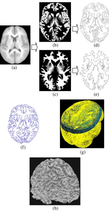
The accurate 3-D model was constructed from 150 cross-sec-tional MRI slices of the brain (which are just 2 mm apart). For each slice, special graphics editing tools were used to accurately detect edges (isolines) of white and gray matters and filter the isolines. These slices were then stacked vertically and lofted before external bounding surfaces of matters were created by using nonuniform rational B-spline (NURBS). Typically, this would, for example, create more than 30000 NURBS surfaces for the white matter which very accurately represents its intri-cate geometric features. These also provide additional flexibility in the FE models to easily take differences in brain geometry into account that may be encountered in realistic geometry brain models. Fig. 1 shows a schematic representation of the process described before.
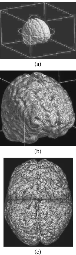
[image:3.595.307.535.99.539.2]The complex polysurfaces [shown in Fig. 2(a) and (b)] ob-tained before by NURBS surfacing are further smoothed and, if required, the number of surfaces is reduced by merging sev-eral surfaces. This is then followed by connecting these surfaces to relevant solid objects. The gray and white matters with 3-D
Fig. 1. Preparation of cross-sectional MRI slices (altogether 150, 2-mm-apart slices) to build a 3-D solid model. (a) Typical MRI slice. (b) Accurate detection of edges of gray and (c) white matters. (d) Resulting edges (isolines) of gray and (e) white matters, (f) “extrusion” of isolines in the third dimension (vertically in the z-direction), (g) 150 edge-detected MRI slices stacked vertically before lofting, and (h) lofted and NURBS surfaced stack of white matter containing 31 000 surfaces.
polygonal meshes are then combined together by a solid mod-eler to obtain the 3-D solid model of the brain shown in Fig. 2(c). It has been found that the large number of polysurfaces of which this solid model is made of can pose substantial problems in ex-porting these data (solid model) to an EM solver which may have limitations in manipulating such models. It is, therefore, recommended that the number of these surfaces should be min-imized without compromising the accuracy of geometric repre-sentation.
Fig. 2. Further processing of lofted and NURBS surfaced stack of MRI slices to obtain a 3-D solid model before subsequent finite-element discretization. (a) 3-D polygonal NURBS surfaces for white and (b) gray matter; (c) resulting solid model of the gray matter after smoothing, reduction, and merging of poly-surfaces (640 poly-surfaces).
hardware for field solution. The resulting 3-D FE model of the brain used in this paper is shown in Fig. 3. A cubic air region, placed sufficiently far away from the brain itself, was used to represent the total problem domain [Fig. 3(a)]. The zero boundary condition was used on all of the surfaces of this cube. For the 3-D FE mesh shown in Fig. 3(b) and (c), tetrahedral FE elements with good aspect ratio and regularity were used to rep-resent the brain geometry and physical properties as accurately as was practicable (defined by a tradeoff between the number of elements and accuracy of topological representation).
Table I shows some of the main parameters for a typical model used in this paper. The seemingly large number of elements (more than 1.35 m) shown is typically required to take various internal and surface geometric features of a human brain accurately into account.
Fig. 3. Full 3-D realistic geometry and realistic material-property brain model. (a) Brain model within the problem domain containing the 3-D surrounding air region and (b) and (c) details of the FE mesh used.
TABLE I
MODELPARAMETERS
III. SOMERESULTS ANDDISCUSSIONS
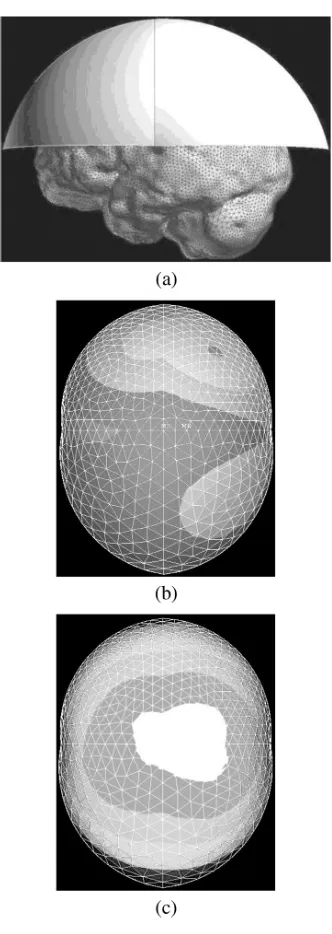
[image:4.595.104.238.105.514.2]Fig. 4. Some of the initial results. (a) 3-D brain model with imaginary “sensor surface” above the head on which some of the modeling results were plotted for comparison and validation purposes. (b) Magnetic-field distribution for a current loop placed vertically and (c) horizontally near the center of the brain.
above the head [Fig. 4(a)] on which some of the modeling re-sults were plotted and compared with known analytical solu-tions for given source configurasolu-tions. Two examples of such so-lutions are shown in Fig. 4(b) and (c). These figures show the magnetic-field distributions for a circular current loop placed near the center of the brain. The particular choice of a circular current loop (up to 10 mm in diameter carrying various currents,
say 1 A for validation with known analytical solutions only) is attributable to the fact that it represents a line source with a lo-calized surface topology. The magnitude and the distribution of the field are in good agreement with the known solution for such configurations. These and other modeling results confirm the ac-curacy and, to some extent, the developed flexibility of the brain model.
IV. CONCLUSION
It is believed that this paper presents the most accurate 3-D realistic FE model of the brain developed so far for solving the forward problem in MFT brain imaging based on MEG. With more than 1.3-m finite elements (extendable up to 5 m), this model provides flexibility in representing the complex internal features and surface topology of the human brain as well as its material inhomogeneity. It can also accommodate, with relative ease, any primary source conductor configurations in terms of its geometry and material properties. To solve the forward problem in MFT, in this paper, only the main body of the brain, in which the flow of biomagnetic currents takes place during cognitive processing, was taken into account. Hence, the skull and other “nonbrain” matters within the skull were justifiably ignored for modeling purposes since they have no influence on the mag-netic-field distribution at the very low frequencies involved.
ACKNOWLEDGMENT
This work was supported in part by the Department for Inno-vation, Universities and Skills (DIUS), U.K., and in part by the British Council under a BRIDGE (British Degrees in Russia) Research Cooperation Grant between City University London and St. Petersburg State Polytechnic University, St. Petersburg, Russia.
REFERENCES
[1] N. von Ellenrieder, C. H. Muravchik, and A. Nehorai, “MEG forward problem formulation using equivalent surface current densities,”IEEE Trans. Biomed. Eng., vol. 52, no. 7, pp. 1210–1217, Jul. 2005. [2] D.-H. Kim, C. Won, and G. E. Georghiou, “Assessment of the
sen-sitivity to field localization of various parameters during transcranial magnetic stimulation,” IEEE Trans. Magn., vol. 43, no. 11, pp. 4016–4022, Nov. 2007.
[3] C. H. Wolters, A. Anwander, X. Tricoche, D. Weinstein, M. A. Koch, and R. S. MacLeod, “Influence of tissue conductivity anisotropy on EEG/MEG field and return current computation in a realistic head model: A simulation and visualization study using high-resolution finite element modeling,”NeuroImage, vol. 30, pp. 813–826, 2006. [4] M. Hamalainen, R. Hari, R. J. Ilmoniemi, J. Knuutila, and O. V.
Lounasmaa, “Magnetoencephalography-theory, instrumentation, and applications to noninvasive studies of the working human brain,”Rev. Modern Phys., vol. 65, no. 2, pp. 413–497, 1993.
[5] R. V. Uitert, D. Weinstein, and C. Johnson, “Volume currents in for-ward and inverse magnetoencephalographic simulations using realistic head models,”Annals Biomed. Eng., vol. 31, pp. 21–31, 2003. [6] J. Haueisen, D. S. Tuch, C. Ramon, P. H. Schimpf, V. J. Wedeen, J. S.