Version: Accepted Version
Proceedings Paper:
Demetriou, D, Nikitas, N and Tsavdaridis, KD (2014) Performance of
proportional-integral-derivative controllers on structures with variable damping active tuned
mass dampers. In: The 6th World Conference on Structural Control and Monitoring. The
6th World Conference on Structural Control and Monitoring - Special Session 12:
Advanced Modeling for Structural Control, 15-17 July 2014, Barcelona, Spain. 6WCSCM .
[email protected] https://eprints.whiterose.ac.uk/
Reuse
Unless indicated otherwise, fulltext items are protected by copyright with all rights reserved. The copyright exception in section 29 of the Copyright, Designs and Patents Act 1988 allows the making of a single copy solely for the purpose of non-commercial research or private study within the limits of fair dealing. The publisher or other rights-holder may allow further reproduction and re-use of this version - refer to the White Rose Research Online record for this item. Where records identify the publisher as the copyright holder, users can verify any specific terms of use on the publisher’s website.
Takedown
If you consider content in White Rose Research Online to be in breach of UK law, please notify us by
1
Abstract: The present study investigates the effectiveness of a Proportional-Integral-Derivative (PID) controlled Variable Damping Semi-Active Tuned Mass Damper (VD-STMD) on reducing the vibration response of an earthquake excited multi-storey structure. The effectiveness of the controlled system is evaluated by comparing the structure’s overall dynamic behavior against that of an equivalent similar structure equipped with a conventional optimally designed passive Tuned Mass Damper (TMD). The numerical simulations show that the structure equipped with the PID controlled VD-STMD has improved vibration attenuation metrics when compared to the one equipped with the optimal TMD. From the numerical simulations, it was also evident that when material degradation and structural damage is considered, the TMD becomes instantly de-tuned resulting in reduced vibration mitigation performance. On the contrary, the VD-STMD controlled system remains insensitive to the stiffness parametric variation, suggesting the suitability of such systems in structural applications sustaining damage or in general change.
I. INTRODUCTION
The drive towards elegant and sustainable structural systems along with the trend for skyward expansion entailed the design of slender and lightweight high-rise structures. Such structures are benefited by lower material, foundation and space requirements, and are also faster to erect when compared to conventionally designed, rigid structures. From a structural point of view, the increased flexibility and lower damping associated with such structures implies inherent problems such as excessive and long pertaining vibrations. Their vulnerability under dynamic loading increases the structure’s failure risk and issues associated with their serviceability. In this regard, over the last decades alternative approaches are constantly investigated so that structural designs fully satisfy both the extra serviceability and sustainability requirements.
To date, most of the research has been focused on concepts of structural control in line with the definition of Yao [1]. Structural control and its notion as an alternative approach for addressing the serviceability and safety problem in structural engineering systems led to the development of a range of passive, active and hybrid techniques for structural vibration mitigation. Amongst the most reliable and effective control techniques is the use of tuned mass dampers (TMDs) as energy absorbing devices. The TMD was firstly introduced in the engineering community by Frahm in 1911[2] and since then a large number of studies have been published validating the applicability and enhanced performance for a combination of different TMD devices and configurations of structural systems [3-6]. While TMDs have been proven to be successful at alleviating structural response under generic dynamic loading, such devices being tuned to a single mode of the structure’s vibration are limited to a narrow band of operating frequencies [7]. This limitation of the TMD is quite significant particularly when dealing with high-rise structures excited in more than the first few modes. An additional and important limitation of the use of TMD is its sensitivity to parametric variation of the structural system. When parametric variation occurs either as a result of material degradation or structural damage (or e.g. due to environmental conditions; see aerodynamic stiffness), a purely passive TMD will unavoidably become de-tuned resulting in reduced vibration attenuation capacity and even in some cases increase of the vibration levels of the system, due to its neighboring side lobes strength [8-10].
Recognizing the limitations of the TMD, many efforts have been made to improve and tailor the system’s performance by incorporating active and semi-active control in the purely passive TMD device. These control methods have the ability of online accessing and altering the system’s dynamic characteristics and in a sense “tune” the TMD in real-time so that it adapts better to the external disturbances as well as cope with any parametric variation in the structural system and in turn maintain desired performance throughout its lifecycle of operation. The first and most effective method of control, namely the active control of TMDs, (ATMDs), act by directly modifying the energy of the system by means of mechanical actuation. Although such systems are typically benefitted by improved vibration attenuation performance, they suffer from high power demands, relevant implementation hurdles and potential unstable operation. On the contrary, Semi-Active-Tuned-Mass-Dampers (STMDs) work on the basis of indirectly applying control forces to the structural system i.e. by varying the stiffness or damping of an element attached to the structure, using methods such as controlling the fluid discharge through an orifice or varying the magnetic field around a ferrous-fluid piston (i.e. Magneto-Rheological (MR) dampers). STMDs have shown comparable performance to ATMDs [10], but have also the benefit of guaranteed bounded-input bounded output stability, lower power demand (an order of
*Research supported by EPSRC/TATA STEEL.
D. Demetriou is with the School of Civil Engineering, University of Leeds, Leeds, LS2 9JT UK (corresponding author, phone: +44 (0)113-343-2901; fax: +44 (0)113-343-2265; e-mail: [email protected]).
N. Nikitas, is with the School of Civil Engineering, University of Leeds, Leeds, LS2 9JT UK (e-mail: [email protected]).
K. D. Tsavdaridis is with the School of Civil Engineering, University of Leeds, Leeds, LS2 9JT UK (e-mail: [email protected]).
Performance of Proportional
-
Integral
-
Derivative Controlled
Variable Damping Tuned Mass Dampers
magnitude less power than the ATMD) [11] and low cost of implementation [12-14].These factors, establish STMDs as an attractive alternative for use in most civil engineering structural systems.
A STMD attains its dynamic tuning and energy dissipation capabilities using variable stiffness (VS), variable damping (VD) or a combination of both elements. Reviewing the equations of motion and the effect of stiffness and damping variation on the dynamic characteristics of the system, it can be observed that stiffness variability is associated with moving the system’s natural frequency outside the resonance range. If that is the case, a method for capturing the instantaneous localized time-varying frequency content of any given signal is essential for the variable stiffness device to make appropriate adjustments. For this reason, over the last years new real time tuning algorithms based on Hilbert Transform (HT) and short time Fourier Transform (STFT) have been developed [10]. On the contrary, when damping variability is considered the change in the energy dissipation capacity of the system is typically exploited. If the damping variability is assumed to influence only the energy dissipation capacity of the system without influencing its frequency response, classical control methods for deriving the required control actions can be used [12]. It is worth noting that although variable damping devices have the capacity of altering the system’s damped natural frequency and re-tune the system, the damping ratio would need to be increased substantially to achieve this objective, something that might defeat the original purpose of using a TMD as a tuning device [10]. In the structural engineering field, most of the studies to date exploit stiffness variation probably due to the ease of introduction of stiffness variability in the system as well as its effectiveness in tuning the system when compared to variable damping methods [15]. Examples of studies on variable stiffness STMD (VS-STMD) are found in [9, 11, 16, 17], whereas examples of studies on variable damping STMD (VD-STMD) can be found in [15, 18-22]. Reviewing these studies it is found that both VD-STMD and VS-STMD have a significant performance advantage over the traditional TMD.
As already discussed, a VD-STMD achieves optimal operation, by varying the device’s parameters via a control method. Three of the most popular control methods are based on: 1) Classical control 2) Neural network control and 3) Fuzzy logic control. In the area of neural network and fuzzy logic control, several studies examining the performance of dynamic vibration absorbers have been undertaken [23-27]. Classical control methods which include both open-loop and closed-loop control is often the preferred approach due to simplicity of implementation and computational efficiency. While open-loop control can be used successfully in many control applications, its use in structural applications is not preferable due to the fact that the dynamic loading is not known a-priori. Consequently, from the two approaches of classical control, closed-loop/feedback control is prevalent in literature.
Amongst the most popular control algorithms developed for closed-loop systems, groundhook control [15, 19-21], clipped optimal control [18, 20, 28, 29] and bang-bang control [30] have been extensively studied in the literature. Another famous control algorithm developed based on classical control theory, is the Proportional-Integral-Derivative controller (PID). PID controllers are amongst the most widely used control loop mechanisms in the industry because of their remarkable effectiveness and simplicity of implementation [31]. As matter of fact, in the refining, chemical and pulp and paper industries, 97% of regulatory controllers utilize PID feedback [32]. Despite the fact that PID controllers represent a great portion of industrial controllers, their use in civil structural control applications is scarce [33]. The rejection of the classical PID controller in structural applications might be primarily linked to the view that complex structural systems with uncertain and varying parameters subjected to unknown loading conditions cannot be captured easily with such controllers [25]. For this reason, a number of researchers suggest that other robust control methods are offered for achieving the control objective [34]. Nevertheless, a few studies can be found in literature examining PID control performance in structural engineering applications. Guclu and Sertbas [34] examined the performance of a five Degree-Of-Freedom (DOF) structure incorporating an active tuned mass damper subjected to earthquake excitation; they observed no significant improvement in structural response, suggesting that robust controllers are preferable. They validate their arguments by comparing the performance of the PID controller with the performance of a sliding mode controller (SMC) demonstrating that the latter controller is much more effective. Guclu and Yazici [35] examined the performance of a PID controller for vibration suppression of a fifteen-DOF structure using an active isolator. The numerical results showed an improved reduction in the displacement response but only minimal effects on the acceleration responses of the top storey. More recently, Casciati and Chen [36] developed a PID controller for implementation in a three storey experimental structure incorporating an ATMD. The experimental results clearly indicated reduction in top floor accelerations. In a similar study, Boujari et al. [37] examined the performance of a three-DOF structure subjected to four real earthquake ground acceleration records. The structure was controlled by an ATMD and the control forces were generated by a PID controller. They observed a significant increase in performance both in terms of acceleration and displacement response reduction.
The paper is structured as follows. The immediately following section presents the procedure followed for the derivation of the semi-active forces and the resulting equations of motion needed to accurately capture the behavior of the semi-actively controlled structural system. Section III describes the controller used for obtaining the forces and in turn the damping variability. The systems used in the numerical simulations are explicitly described in section IV. Section V presents the numerical results for the cases of uncontrolled (no TMD), passive (TMD) and semi-active (PID-controlled VD-STMD) structures. Concluding remarks and recommendations for future work are made in the final section.
II. MODELING THE VD-STMD CONTROLLED SYSTEM
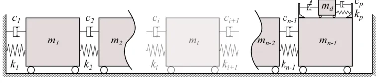
A single mass damper’s operational principle can be easily explained when considering a simple MDOF structure as the one shown in Fig.1. The dynamic behavior of such a system when subjected to an arbitrary disturbance is fully captured by its matrix equation of motion:
Mx( )t Cx( )t Kx( )t Bu t( )Dd( )t , (1)
[image:4.595.118.499.354.438.2]where M, C and K are the n × n mass, damping, and stiffness matrices respectively; x(t) and d(t) are in order the displacement, and external force n × 1 column vectors; u(t) is the single scalar control force and B and D are the n × 1 influence matrices assigning the control and external force contributions respectively to the individual DOFs. For each DOF in x(t) being the displacement of the ith (i=1-n) mass, M trivially becomes diagonal, while for the pure viscous damping considered (and connections as in Fig. 1) the damping matrix C attains a form identical to the symmetric stiffness matrix K. Without any loss of generality the mass damper device is attached to the (n-1)th DOF and its motion constitutes the nth DOF.
Figure 1. Idealised n-DOF structural system equipped with a mass damper
The matrix Eq. (1) could describe a system equipped with any type of viscous dynamic absorbing device. The difference between passive, active and semi-active schemes would exclusively be captured by the nature of the control force u(t). It
would be probably more appropriately for this case to term u(t) interaction force, yet for economy in presentation the term
control is used throughout. To facilitate the derivation of a semi-active control force, it would be beneficial to first consider
the case of a purely passive TMD. When the TMD is attached to the system of interest, the u(t), takes the form of a purely
passive action, up(t), resulting solely from the motion of the absorber’s mass . This passive force which couples the damper to
the rest of the system can be mathematically expressed as:
u t
p( )
c x t
p r( )
k x t
p r( )
. (2)In the equation above, cp is the constant scalar damping coefficient and kp is the constant scalar spring stiffness of the TMD,
while r(t) and xr(t) are respectively the relative velocity and displacement between the nth and (n-1)th DOFs. It should be also
noted that the n-element B becomes [0… 1 -1]T. Next step towards the derivation of the semi-active control force is to formulate an equivalent control force provided by a purely active-TMD (ATMD) [18].When an active control system is considered, the control force takes the form of a desired action, ua(t), determined by a control algorithm such as a Linear-Quadratic-Regulator
(LQR), PID or similar. For an ATMD, the desired force is the summation of the passive forces generated by the mass damper’s motion and an additional external force provided by means of mechanical actuation. Because the dynamic characteristics of the mass damper remain unaltered and the desired interaction force, ua(t), has been already calculated by the control algorithm, the
required actuation force, fa(t) , can be readily determined from:
u t
a( )
c x t
p r( )
k x t
p r( ) f ( )
at
. (3)( ) f ( ) 1 sgn[f ( ) ( )] 2
a r
sa a
t x t
u t t , (4)
sgn( ) 1 for 0
1 for 0
a
q q
q . (5)
The product of fa(t) r (t) is the power, qa, of the whole active system device. Similarly, the power of just the semi-active
component is defined as the product of the force that can be physically translated by the device, usa(t), and its relative velocity,
r :
qsa usa( ) ( )t x tr < 0 (6)
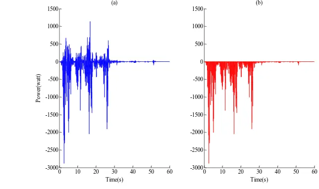
A schematic representation of the power time histories of both an actively and a semi-actively controlled devices is shown in Fig. 2. It can be observed that the active device has the advantage of both producing and consuming power while the semi-active device only consumes power. This verifies the fact that an semi-active control scheme can add energy to the system while a semi-active scheme can only dissipate energy.
Figure 2. Indicative power demand of an a) Active device and a b) Semi-active device
So far, the principle of obtaining a “desired” control force to be provided by a semi-active device has been discussed. When a VD-STMD is considered, the chosen way of achieving optimum performance, is by appropriately timely adjusting the damping coefficient of the device within bands, in order for the required control force to be reached. By referring back to the system presented in Fig. 1, one can express the semi-active damping force contribution as csa(t) r. Inspection of Eq. (6) easily leads to
csa(t)<0. Updating Eq. (3), the resulting overall control force provided at each time instance by a VD-STMD can be expressed
mathematically as:
( )( ( ) ) ( ) ( )
a sa p r p r
u t c t c x t k x t . (7)
In Eq. (7) the time varying semi-active damping coefficient, csa(t), is the only unknown. Therefore, calculating the real-time
variation of the damping coefficient is straight forward.
III. CONTROL STRATEGY
As already discussed in the previous section, obtaining the “desired” control force to be provided by a VD-STMD involves the calculation of an equivalent total active interaction force. In this study, this active force is calculated by a PID controller because of its remarkable effectiveness and simplicity of implementation [31, 33]. A PID controller works on the basis of calculating the required control force based on a calculated feedback error e(t). For a negative feedback system, the error, e(t), is defined as the difference of the output signal, y(t), to a desired reference signal, r(t). It is worth noting that for structural applications, the desired state is the equilibrium position, thus the reference signal takes a constant value of zero. Once the feedback error is calculated from e(t)= r(t)-y(t), the controller’s objective is to minimize the error for the next iteration by appropriately adjusting the inputs ua(t) to the plant. A schematic representation of a negative feedback control loop is shown in
Fig. 3. Using the “textbook” version of the PID controller, the desired control inputs that minimize the feedback error are calculated by [32]:
0 10 20 30 40 50 60
-3000 -2500 -2000 -1500 -1000 -500 0 500 1000 1500
Time(s)
P
o
w
er
(w
at
t)
(a)
0 10 20 30 40 50 60
-3000 -2500 -2000 -1500 -1000 -500 0 500 1000 1500
(b)
[image:5.595.140.462.292.483.2]
0
1 ( )
( )
(
( ) ( ))
tf
a d
in
de t
u t K e t e t dt T
T dx
, (8)where K is the proportional gain, Tin is the integral time, Td is the derivative time and tf is the control time. Using simpler
notation, the above equation can be written as:
0
( )
( ) ( ) ( )
tf
a p in d
de t
u t K e t K e t dt K
dx
. (9)In this equation, Kp= K is the proportional gain, Kin= K / Tin is the integral gain and Kd = Td K is the derivative gain. It can be
observed from the above expressions that the plant input signal, ua(t), is the summation of these three terms: The proportional
(P) term the integral (I) term and the derivative (D) terms. The engineering challenge is to appropriately adjust, i.e. “tune”, the control gains Kp , Kin , Kd such as given a feedback error e(t) at any instance in time the controller outputs will generate
[image:6.595.193.423.313.408.2]desirable plant inputs making the system behave in accordance to predefined performance objectives such as rise time, overshoot, settling time, steady state error etc. Different tuning techniques have been proposed in the literature to achieve these objectives including the popular Ziegler-Nichols and Cohen-Coon methods. In this paper, the PID control gains were obtained manually so as to satisfy strict performance objectives when the system is subjected to unit step input. In regards to this, rise time of less than 0.05s, overshoot less than 10% and settling time less than 1s is selected.
Figure 3. Closed loop negative feedback system
IV. NUMERICAL INVESTIGATION
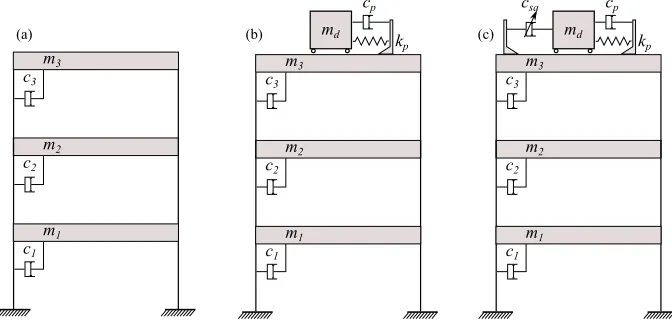
In this section the potential application of a PID controller in a structural system comprising a VD-STMD is investigated. To illustrate the effectiveness of the PID controller at alleviating structural response a three-storey lightly damped structure excited by a number of real earthquake ground motions is considered. The parameters of the structure can be found in Table II at the end of the paper. The dynamic response of this structural system has been previously studied by Boujari et al [37] and the same system has been also used as a simple experimental frame in the structural dynamics and Control/Earthquake Laboratory (SDC/EEL) at the University of Notre Dame. In this study, three alternatives, namely: uncontrolled (no-TMD), passive (TMD) and semi-active (VD-STMD) controlled structures were used for the investigation of the relative performance of the VD-STMD device. For the passive and semi-active variants, the TMD and VD-STMD are placed at the top of the structure as shown in Fig. 4. For the semi-active case, the displacement of the 3rd floor was used as the feedback measurement, y(t), in the PID controller. Since the sensor and the actuator are attached to the same DOF, the resulting semi-active system takes the form of a collocated control setup.
[image:6.595.142.478.601.764.2]In order to quantify the effectiveness of the semi-active system, the integrated time response of the structure equipped with a VD-STMD is compared with the integrated time response of the same structure equipped with a TMD. As earlier stated, the TMD was tuned optimally i.e. the dynamic characteristics of the damper have been selected in such way that its vibration attenuation performance is maximized. In this context, for optimal performance the mass ratio, µ, of the TMD to the total structural mass (i.e. µ =md/m3) is taken as 1% (this being a rather small and practical value) while the tuning frequency was
calculated using the relationship given by Den Hartog [38]:
1 1 1 d opt str f f
f , (10)
where fopt is the optimal frequency ratio, fd is the frequency of the damping device andfstr is the structural frequency of the
vibration mode to be controlled. Because the objective of the study is to control top-storey responses, the TMD is tuned to the first fundamental frequency of the structure (the lowest frequency with the largest amplitude on the storey of interest) .After examining the system’s eigenvalues the fundamental frequency,fstr , was calculated to be approximately 5.4 Hz (the others at
15.8 Hz and 23.6 Hz). From this, the stiffness of the mass damper connection, kp, required to achieve optimal tuning was readily
calculated by:
2
p d d
k m f . (11)
Unlike the stiffness, the optimal damping ratio of the TMD is found by trial and error to be 8% of the critical damping. While the TMD and STMD share the same stiffness characteristics, the active damping component, csa(t),of the VD-STMD ranges
from 0 to 100% of the critical damping. Its passive damping component, cp, is kept at 2 Ns/m, which is equivalent to 1% of
critical damping. The stiffness, damping and control force matrices of the passive and semi-actively controlled structures can thus be calculated as:
1 1 2 2 1 2 2
2 2 2 3 3 2 2 3 3
3 3 3 3 3
0
0 0 0 0 0 0 0 0
0
0 0 0 0 0 0
, , , ( ) , ( )
0 0 0 0 0 0 0
0 0 0 0 0 0 0 0 0 0 0
M K C B p B a
p a
p
d a
m k k k c c c
m k k k k c c c c
u t u t
u
m k k c c u
u
m u
, (12)
where up and ua are given by Eq. (2) and Eq. (7) respectively.
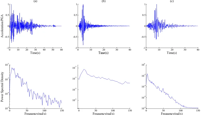
[image:7.595.115.504.539.763.2]Each of the three different models in Fig. 4 was subjected to the inherently non-stationary earthquake time histories of the 1940 El-Centro, Northridge and Loma Prieta. Fig.5 presents the acceleration time histories along with the power spectral density for each of the three earthquakes. The earthquakes were selected so that their frequency content could excite the modes of the system in qualitatively different ways. More information about the selected earthquakes can be found in Table III in the Appendix.
Figure 5. Time acceleration histories and auto-power spectral densities of (a) 1940 El Centro, (b) Loma Prieta and (c) Northridge earthquakes
0 10 20 30 40 50 60
-1 -0.5 0 0.5 1 (a) Time(s) A c c e le ra ti on/ P G A
0 10 20 30 40
-1 -0.5 0 0.5 1 (b) Time(s)
0 10 20 30 40
-1 -0.5 0 0.5 1 (c) Time(s)
0 50 100 150
10-5 10-4 10-3 10-2 Frequency(rad/s) P ow e r S pe c tr a l D e ns it y
0 50 100 150
10-8 10-6 10-4 10-2
Frequency(rad/s)
0 50 100 150
As a final step, the performance of the passive and semi-active devices when material degradation and/or damage take place is investigated. To adequately capture these phenomena, the stiffness of the primary structure has been decreased uniformly in 5% steps to a maximum of 25% reduction of the initial nominal stiffness.
V. SIMULATION RESULTS
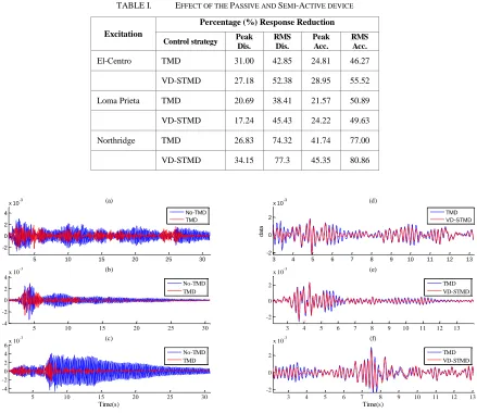
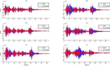
[image:8.595.92.531.320.700.2]In order to get illustratively the insights on the performance of the PID-controlled VD-STMD structural system, the comparison with its uncontrolled and passively controlled counterparts should focus on response metrics and attributes of the interaction forces. The performance comparison was based on four criteria namely, peak displacement response, peak acceleration response, rms displacement response and rms acceleration response. Table I summarizes the percentage response reduction of each of the passively and semi-actively control schemes when compared to the response of the uncontrolled structure. To aid the comparison, the displacement response of the 3rd floor for each of the three earthquakes is shown in Fig. 6. For clarity, Figs. 6 (d)-(e) present only a selected part with considerable oscillatory amplitude to aid the distinction of the TMD and VD-STMD equipped systems. Complementing the results in the time-domain, the measured frequency response functions of the system subjected to a chirp signal with a frequency range of 0.1 – 40 Hz were obtained and demonstrated in Fig. 7. This should give indicatively the full dynamic information for both the linear uncontrolled and TMD systems as well as for the piece-wise linear VD-STMD system.
TABLE I. EFFECT OF THE PASSIVE AND SEMI-ACTIVE DEVICE
Excitation
Percentage (%) Response Reduction
Control strategy Peak Dis.
RMS Dis.
Peak Acc.
RMS Acc.
El-Centro TMD 31.00 42.85 24.81 46.27
VD-STMD 27.18 52.38 28.95 55.52
Loma Prieta TMD 20.69 38.41 21.57 50.89
VD-STMD 17.24 45.43 24.22 49.63
Northridge TMD 26.83 74.32 41.74 77.00
VD-STMD 34.15 77.3 45.35 80.86
Figure 6. Displacement time histories of the 3rd storey of the buildings in Fig. 5; Plots (a)-(c) show the full time history under the El Centro, Loma Prieta and
Northridge earthquakes respectively. Plots (d)-(f) focus on limited portions of the the time histories for the same earthquakes
5 10 15 20 25 30
-2 0 2 4
x 10-3
d
a
ta
(a)
3 4 5 6 7 8 9 10 11 12 13 -2
0 2
x 10-3
d
a
ta
(d)
5 10 15 20 25 30
-4 -2 0 2
4x 10
-3 (b)
x
(m
)
3 4 5 6 7 8 9 10 11 12 13
-2 0 2
x 10-3 (e)
5 10 15 20 25 30
-4 -2 0 2 4
6x 10
-3
Time(s)
x
(m
)
(c)
3 4 5 6 7 8 9 10 11 12 13
-2 0 2
x 10-3
Time(s) (f)
No-TMD TMD No-TMD TMD
TMD VD-STMD No-TMD
TMD
TMD VD-STMD
Figure 7. Frequency response estimates for the structure under the influence of a) TMD and b) VD-STMD devices
Figure 8. Perfrormance of PID controlled STMD vs TMD at reduced structural stiffness: (a) 0% - no reduction (b) 5% (c) 10%(d) 15%(e) 20% (f) 25%
Table I and Figs. 6 and 7 illustrate that the vibration attenuation performance of a VD-STMD when compared to the optimal TMD is better averaging an additional 5-10% reduction in RMS displacement response. While this demonstrates the potential of the PID-controlled VD-STMD device at alleviating vibrations, the TMD showed a slightly better performance when only peak ground displacements are considered. Yet, obviously the main threatening parameter when considering vibration cycles is their longevity rather than instantaneous single peak. When damage and/or material degradation occurs in the structural system, the TMD quickly becomes detuned resulting in a significantly reduced vibration attenuation capacity. On the contrary, the PID controlled VD-STMD is shown to be insensitive to the parametric variation and managed to maintain satisfactory performance.
0 5 10 15 20 25 30
10-5 10-4 10-3 10-2 10-1 Frequency (Hz) C P S D(i n p u t-o u tp u t) / P S D(i n p u t) No-TMD VD-STMD TMD
5 10 15 20 25 30 35 40
-3 -2 -1 0 1 2
x 10-3
x
(m
)
(a)
0 5 10 15 20 25 30 35 40
-4 -2 0 2
x 10-3 (d)
0 5 10 15 20 25 30 35 40
-3 -2 -1 0 1 2
x 10-3 (b)
x
(m
)
0 5 10 15 20 25 30 35 40
-4 -2 0 2
x 10-3 (e)
0 5 10 15 20 25 30 35 40
-3 -2 -1 0 1 2
x 10-3 (c)
Time(s)
x
(m
)
5 10 15 20 25 30 35 40
-4 -2 0 2
x 10-3 (f)
Figure 9. (a) Bang bang nature of the varying damping coefficient; (b) Forces provided by PID controlled STMD vs TMD; (c) Power of TMD vs VD-STMD
The VD-STMD outperformed the TMD, due to its ability of varying its damping coefficients in real time. The PID calculated actions, varied the damping coefficients in such a way that maximum energy dissipation occurs. As it is shown in Fig. 9a, the damping variation is of bang bang nature i.e. the damping coefficient moves from a minimum to a maximum value. This effect is seen and studied by various researchers [39] who mathematically verify that for second order systems minimum settling times can be achieved when the damping is of this nature. As a matter of fact, this observation is the basis of the development of control algorithms based on groundhook, skyhook and bang-bang control. Fig. 9b represents the total force up(t) and usa(t) provided by both the passive and semi-active damper respectively. The forces provided by the two
devices are of the same magnitude,in order to illustrate the effect of the semi-active device in dissipating energy, the power absorbed by each device was considered. Fig. 9c shows the power consumption of the two devices,however for clarity and illustration purposes, the cumulative power absorbed by each system configuration was examined in Fig. 10.
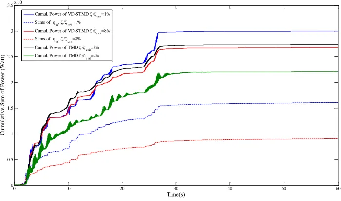
Figure 10. Cummulative power of TMD vs VD-STMD for varying passive damping components, cp
By examining Fig. 10 it is obvious that the total energy (defined as the area under the power vs time curve) absorbed by the VD-STMD, is larger than the energy absorbed by the passive device even at its optimum damping ratio of / crit =8%. In the
same figure, the power ,csa(t) r , absorbed solely by the semi-active component of the VD-STMD is also presented. It can be seen that when the passive damping component of the VD-STMD, cp ,takes a value of 2 Ns/m equivalent to / crit =1% , the
5 10 15 20 25 30
-100 0 100 (b) D am p er F o rc e( N )
1 2 3 4 5 6 7 8 9 10
0 100 200 (a) V ar ia b le d am p in g co ef fi ci en t (N s/ m )
5 10 15 20 25 30
-2 0 2 4 6 Time (seconds) P o w e r( Wa tt ) (c) TMD VD-STMD TMD VD-STMD
0 10 20 30 40 50 60
0 0.5 1 1.5 2 2.5 3 3.5x 10
4 Time(s) Cum ul a ti ve S um of P ow e r (W a tt )
Cumul. Power of VD-STMD /
crit=1%
Sums of qsa, /
crit=1%
Cumul. Power of VD-STMD /
crit=8%
Sums of qsa, /
crit=8%
Cumul. Power of TMD /
crit=8%
Cumul. Power of TMD /
[image:10.595.134.484.499.706.2]contribution of the semi-active component , csa(t) r ,to the energy dissipation of the system is considerably higher (almost double) compared to the system with passive damping, cp ,and a value of 16.3 Ns/m which is equivalent to / crit =8% (equal
to the TMD damping value). In turn it can be observed that the energy dissipation capacity of the semi-actively controlled system with, cp = 16.3 Ns/mhas similar energy dissipation capacity with the purely passive TMD controlled system. The
reader can also realize the method employed for manualy obtaining the optimum damping ration of the TMD. It can be seen that the energy consumed by the damper when / crit =8% is considerably higher compared to the TMD with / crit =2%.
VI. CONCLUSION
In this study, the performance of a PID controlled VD-STMD on enhancing the vibration performance of a multi-storey structure has been investigated. From the numerical simulations, an increase of 5-10% in the system’s vibration attenuation capacity was evident in terms of rms values. To the authors’ belief this might look limited to justify the use of sophisticated equipment for relatively small performance gains; still with the development of very cost efficient control solutions this should definitely be considered as part of the future civil engineering design agenda. Further, when long term performance of both the TMD and VD-STMD was considered by accounting material degradation and damage in the system, the performance of the VD-STMD was significantly better than that of the TMD, pointing out that such devices are not sensitive to parametric variations of the structural system. And it is not only damage owing to shock effects that may alter a system’s dynamic attributes. With that in mind, future work needs to be focused on dealing with:
1. The applicability of such systems in high-rise structures where high-order effects are present.
2. The effect of such systems on controlling a certain mode of vibration other than the first one using the same collocated setup.
3. Performance gains when different tuning methods are employed.
4. Sensitivity of the system to sensor noise, signal delay and actuator dynamics. 5. The effect of mass variation of the VD-STMD compared to the traditional TMD. 6. The cost of implementation of PID vs classical controllers
REFERENCES
[1] Yao JTP. Concept of Structural Control. Journal of Structural Division. 1972:1567-74. [2] Frahm H. Device for damping vibration of vodies. United States: US Patent; 1911.
[3] Xu YL, Samali B, Kwok KC. Control of along-wind response of structures by mass and liquid dampers Journal of Engineering Mechanics. 1992;118:20-39.
[4] Ghosh A, Basu B. A closed-form optimal tuning criterion for TMD in damped structures. Structural Control and Health Monitoring. 2007;14:681-92.
[5] Casciati F, Giuliano F. Performance of multi-TMD in the towers of suspension bridges. Journal of Vibration and Control. 2009;15:821-47. [6] Marian L, Giaralis A. Optimal design of a novel tuned mass-damper-inerter (TMDI) passive vibration control configuration for stochastically support-excited structural systems. Probabilistic Engineering Mechanics. 2014.
[7] Connor JJ. Introduction to Structural Motion Control. Upper Saddle River,New Jersey 07458: Prentice Hall; 2003.
[8] Sun JQ, Jolly MR, Norris MA. Passive,Adaptive and Active Tuned Vibration Absorbers-A Survey. Journal of Mechanical Design 1995;117:234-42.
[9] Nagarajaiah S, Sonmez S. Structures with Semiactive Variable Stiffness Single/Multiple Tuned Mass Dampers. Journal of Structural Engineering 2007;133.
[10] Nagarajaiah S. Adaptive passive, semiactive, smart tuned mass dampers: identification and control using empirical mode decomposition, hilbert transform, and short-term fourier transform. Structural Control and Health Monitoring. 2009;16:800-41.
[11] Nagarajaiah S, Varadarajan N. Short time Fourier transform algorithm for wind response control of buildings with variable stiffness TMD. Engineering Structures. 2005;27:431-41.
[12] Hrovat D, Barak P, Rabins M. Semi-Active Versus Passive or Active Tuned Mass Dampers For Structural Control. Journal of Engineering Mechanics. 1983;109:691-705.
[13] Franchek MA, Ryan MW, Bernhard RJ. Adaptive Passive Vibration Control. Journal of Sound and Vibration 1995;189:565-85.
[14] Jalili N. A Comparative Study and Analysis of Semi-Active Vibration-Control Systems. Journal of Vibration and Acoustics. 2002;124:593. [15] Liedes T. Improving the Performance of the Semi-Active Tuned Mass Damper. Oulu: University of Oulu; 2009.
[16] Bonellol P, Brennan MU, Elliott SJ. Vibration control using an adaptive tuned vibration absorber with a variable curvature stiffness element. Smart Materials and Structures 2005;14:1055-65.
[17] Chen SM, Hung Cf, Chang LM, Chang SH, Zeng JH, Lu TR. Semi-Active Tuned Mass Damper for Vibration Control in High-Tech Fab. Second International Conference on Mechanical,Production and Automobile Engineering(ICMPAE'2012). Singapore2012.
[18] Pinkaew T, Fujino Y. Effectiveness of semi-active tuned mass dampers under harmonic excitation. Engineering Structures. 2001;23:850-6. [19] Koo JH. Using Magneto-Rheological Dampers in Semiactive Tuned Vibration Absorbers to Control Structural Vibrations. Blacksburg,Virginia: Virginia Polytechnic Institute and State University; 2003.
[20] Ji HR, Moon YJ, Kim CH, Lee IW. Structural Vibration Control Using Semiactive Tuned Mass Damper. The Eighteenth KKCNN Symposium on Civil Engineering-KAIST6. Taiwan2005.
[21] Kang J, Kim H-S, Lee D-G. Mitigation of wind response of a tall building using semi-active tuned mass dampers. The Structural Design of Tall and Special Buildings. 2011;20:552-65.
[22] Pastia C, Luca SG. Vibration Control of Frame Structure Using Semi-Active Tuned Mass Damper. Buletinul Institutului Politehnic Din Iasi; 2013. [23] Samali B, Al-Dawod M. Performance of a five-storey benchmark model using an active tuned mass damper and a fuzzy controller. Engineering Structures. 2003;25:1597-610.
[24] Samali B, Dawod MA, Kwok KC, Naghdy F. Active Control of Cross Wind Response of 76-Story Tall Building Using a Fuzzy Controller. Journal of Engineering Mechanics. 2004;130:492-8.
[25] Yang SM, Chen CJ, Huang L. Structural Vibration Suppression by a Neural-Network Controller with a Mass-Damper Actuator. Journal of Vibration and Control. 2006;12:495-508.
[26] Owji HR, Shirazi AHN, Sarvestani HH. A Comparison between a New Semi-Active Tuned Mass Damper and an Active Tuned Mass Damper. Procedia Engineering. 2011;14:2779-87.
[27] Pourzeynali S, Lavasani HH, Modarayi AH. Active control of high rise building structures using fuzzy logic and genetic algorithms. Engineering Structures. 2007;29:346-57.
[28] Dyke SJ, Spenser BF, Quast P, Kaspari DC, Sain MK. Implemetation of an AMD Using Acceleration Feedback Control. Microcomputers in Civil Engineering. 1996.
[29] Dyke SJ, Spencer BF, Quast P, Sain MK, Kaspari DC, Soong TT. Acceleration Feedback Control of MDOF Structures. Journal of Engineering Mechanics. 1996;122:907-18.
[30] Wu Z, Soong TT. Modified Bang-Bang Control Law For Structural Control Implementation. Journal of Engineering Mechanics. 1996;122:771-7. [31] Astrom KJ, Hagglund T. PID Controllers:Theory,Design and Tuning. NC: ISA and Research Triangle; 1995.
[32] Astrom KJ, Murray RM. Feedback Systems-An introduction for scientists and Engineers. New Jersey 08540: Princeton University Press; 2012. [33] Etedali S, Sohrabi MR, Tavakoli S. An Independent Robust Modal PID Control Approach for Seismic Control of Buildings. Journal of Civil Engineering and Urbanism. 2013;3:279-91.
[34] Guclu R, A. S. Evaluation of Sliding Mode and Proportional-Integral-Derivative Controlled Structures with an Active Mass Damper. Journal of Vibration and Control. 2005;11:397-406.
[35] Guclu R, Yazici H. Fuzzy Logic Control of a Non-linear Structural System against Earthquake Induced Vibration. Journal of Vibration and Control. 2007;13:1535-51.
[36] Casciati S, Chen Z. An active mass damper system for structural control using real-time wireless sensors. Structural Control and Health Monitoring. 2012;19:758-67.
[37] Boujari M, Ghorbani-Tanha AK, Rahimian M, Rahami H. Two Degrees of Freedom PID Control for Active Vibration Control of Structures. 15 int WCEE. Lisbon2012.
[38] Hartog D. Mechanical Vibrations. New York: McGraw Hill; 1956.
APPENDIX
The intention is for a reader to be able to reproduce all presented results. To this purpose all the required information for the studied models are provided within the text and the Appendix herein.
TABLE II. PARAMETERS OF STRUCTURAL SYSTEM
Parameter
Structural configuration
No-TMD TMD VD-STMD
m1(kg) 98.3 98.3 98.3
m2(kg) 98.3 98.3 98.3
m3(kg) 98.3 98.3 98.3
md(kg) - 3 3
k1(kN/m) 516 516 516
k2(kN/m) 684 684 684
k3(kN/m) 684 684 684
kp(kN/m) - 3.53 3.53
c1(Ns/m) 125 125 125
c2(Ns/m) 50 50 50
c3(Ns/m) 50 50 50
cp(Ns/m) - 16.3 2
csa(Ns/m) - - PID calculated
TABLE III. SELECTED GROUND MOTIONS
Excitation
Earthquake Characteristics
Magnitude (M) Epicentral
Distance(km)
Peak Ground Acceleration(g)
Peak Ground Displacement (cm)
Peak Ground Velocity(cm/s)
El-Centro 6.95 12.99 0.35 6.12 38.55
Loma Prieta 6.90 28.64 0.47 8.03 33.90
Northridge 6.69 40.68 0.57 4.21 52.10
[image:13.595.107.511.162.444.2]