Interpolation of Sensory Data in the Presence of Obstacles
Dongzhi Zhang and Ickjai Lee
School of Business (IT), James Cook University, Cairns, Queensland, Australia [email protected],[email protected]
Abstract
Due to the inherent discrete nature of sensing, interpolation is a key activity in sensing. In-terpolation in urban computing faces an unprecedented inference issue that was not present in large scale traditional sensing environments. Obstacles such as buildings and walls are preva-lent in urban sensing, and it is important to consider them in urban sensing interpolation. This paper introduces an obstacle handling interpolation in urban sensing where obstacles are present. Experimental results demonstrate that our proposed method outperforms traditional well-known interpolation methods, and test statistics verifies our method significantly improves performance at the expense of small amount of extra time.
Keywords: Interpolation, Obstacle, Sensory data, Urban sensing
1
Introduction
Sensing becomes an important task in urban computing as various sensors are placed in urban settings. As sensors are discretely located, and they cannot cover the entire study area, there is a strong need for estimating values where sensors are not located. That is, it is required to build a continuous sensor map (2.5D contour map) from a set of discrete sensors in many situations. Interpolation is a method of measuring value of a non-sampled point from a set of discrete sensory points, and it is one of the widely studied areas in sensor networks. Therefore, interpolation in urban computing is becoming an increasingly important task as more urban sensors are adopted. One important characteristic that makes interpolation in urban sensing unique and different from interpolation in traditional sensor settings is the presence of obstacles such as walls, buildings and doors. In traditional sensor settings, scales are large and thus obstacles do not directly interfere interactions among sensors. However, this is not the case in urban sensing where scales are small and obstacles block interactions. For instance, sensors for air temperature in a large scale environmental setting are not significantly disturbed by obstacles whilst sensors in urban settings are greatly affected by buildings, walls and other obstacles present.
Interpolation in the presence of obstacles in these urban sensing has attracted no attention in the research field, and this paper is going to investigate effective interpolation approaches in the presence of obstacles for urban sensing. This paper first reviews popular interpolation
Volume 29, 2014, Pages 2496–2506
ICCS 2014. 14th International Conference on Computational Science
methods and obstacle handling techniques, and then proposes an obstacle handling interpolation method based on the most popular interpolation method (inverse distance weighting) with three obstacle handling detour algorithms (A*, Dijstra with ant colony optimization and constrained Delaunay triangulation). Experimental results highlight the promising performance of our proposed methods over traditional interpolation approaches. Various performance measures such as root mean square error, mean absolute error, and Index of Agreementdvalue confirm that our method is well suited for urban sensing environments where obstacles are present. Statistical test verifies the significance of our finding. The rest of paper is organized as follows. Section 2 briefly reviews interpolation and obstacle handing approaches. Section 3 introduces a framework of our proposed method and system, and Section 4 presents experimental results whilst Section 5 draws conclusive final remarks.
2
Preliminaries
2.1
Interpolation
Interpolation is a method of measuring values of non-sampled data from a set of discrete sensory data. In recent years, data interpolation is becoming increasingly important in sensor network and urban sensing. It is required since sensors do not continuously cover the study region, but discretely sense the region. It is an essential process for sensor networks and there exist many interpolation approaches for discrete sensory datasets.
Nearest Neighbor (NN) interpolation is the simplest method for spatial interpolation data. It was commonly used for climatology field in the earlier application domain [13, 16, 17]. NN is also known as Thiessen Polygon method. This generates one polygon for each of the sample point which is located in the center of the polygon. In each polygon, all points are the nearest to its enclosed sample point other than to any other sample points.
Spline function method belongs to mathematical function interpolation with the first deriva-tive and second derivaderiva-tive to be continuous in piecewise polynomial, approximation datum stronghold, and produces smooth and interpolation curve. The polynomials are described by pieces of a line or surface (i.e., they are exactly fitted to a small number of data points) and are integrated so that they can be joined smoothly [1].
The Natural Neighbors (NaN) method combines the features of NN and triangulated irreg-ular network [17]. NaN interpolation is based on Thiessen polygon, a triangulated network of discrete points. In the process of estimating a non-sampled value, the non-sampled point is inserted into the tessellation and then the non-sampled value is calculated by sample points within its adjacent polygons. For each neighbor, the area of the part of its original polygon is integrated in the tile of the new point being calculated. These areas are scaled to sum to 1 and are used as weights to respond to the corresponding sampled data [17].
Linear interpolation is one of the simplest interpolation methods. There is a polygonal line generated when linear interpolation is applied for a sequence of points. In the polygonal line, each straight line segment links two consecutive points of the sequence.
There is a very small difference among them, so the generated interpolation surfaces are about the same.
The Inverse Distance Weighting (IDW) is the most commonly used spatial interpolation method for earth science. IDW method estimates the value at a non-sampled point using a linear combination of values at sampled points weighted by an inverse function of the distance from the non-sampled point to the sampled points. It is based on the principle of similarity. If two objects are closer to each other, their properties are more similar. If two objects are farther away, the similarity is less likely. The weight formula is:
λi= 1/d
p i
n
i=11/dpi
, (1)
where di is the distance between estimated value x0 and the sample value xi, p is a power estimated value estimated valuex0and the sampled parameter andnrepresents the number of sampled points for estimating. The main factor that affects the accuracy of IDW is the value of the power parameter [13]. The weight of each observation is determined by the distance between interpolated points: the shortest distance, the larger weight, the longer distance, and the smaller weight. They are inversely related as weight decreases while the distance increases. So there are heavier and more considerable influencies for closer sample points for the estimation [13]. Notably, the distance function is non-linear. The choice of power parameter and radius of area is arbitrary [17]. The most popular choice of pis 2 and the resulting method is often called inverse square distance or inverse distance squared. The power parameter can also be chosen on the basis of error measurement, such as minimum mean absolute error, resulting the optimal IDW [4]. The smoothness of the estimated spatial continuous surface increases with the power parameter increasing. It is found that the estimated results become less satisfactory when p is 1 and 2 comparing with pequals to 4 [16]. IDW is regarded as moving average when p is 0 [2, 12, 14]. It becomes linear interpolation whenpis 1 and “weighted moving average” when pis not equal to 1 [1]. A detailed comparison of interpolation methods suggests that IDW is a solid candidate for interpolation in the presence of obstacles, thus, it is chosen as a default method for obstacle interpolation in this study.
2.2
Obstacle Handling Approaches
There are unique characteristics of sensing in urban sensing environments that are different from traditional environments. One of them is the presence of obstacles such as walls or build-ings. There are three approaches to deal with this issue of obstacle avoidance: Constrained Delaunay Triangulation (CDT), Dijkstra-Ant Colony Optimization (Dij-ACO) and A*. Dijk-stra’s algorithm [6] is also known as the single source shortest path problem and a graph from one vertex to the rest to solve the shortest path problem. The algorithm finds the shortest path from a source node to every other node. It has been widely used for many applications, and many implementations are available for use. Please refer to [6] for more details. Ant Colony Algorithm (ACO) is one of the latest development to simulate ants foraging behavior bionic optimization algorithm [7]. There is a highlighted applicable characteristic of ACO algorithm to solve combinatorial optimization problems [3, 5, 10]. Dij-ACO includes three steps: (1) estab-lishing a free space model in the presence of obstacles according to MAKLINK graph theory [9]; (2) using the Dijkstra algorithm to find a sub-optimal collision-free path; (3) utilizing the ACO algorithm to optimize the location of the sub-optimal path for generating the globally optimal path (detour distance).
performance and accuracy. A* is the shortest path finding algorithm which uses heuristic search technique to find the least-cost path from the start node to the target node. The classic representation of A* algorithm is as follows:
f(x) =g(x) +h(x), (2)
wheref(x) is called the distance-plus-cost heuristic function orF cost, it is equal to path-cost functiong(x) plus heuristic functionh(x). The path-cost functiong(x),Gcost, it is the actual total cost of the path from the start node to current node x. The heuristic function h(x) is the estimated cost or H cost, it is the path cost from current node xto the target node. h(x) is an admissible heuristic estimation. A heuristic function can be accepted if the cost of path estimation never exceeds the lowest-cost path. The h(x) is an element of f(x), f(x) is dependable on h(x) for the lowest cost of path. It means when h(x) is accepted, there is a shortest path generated from A*, if exists. Therefore,h(x) must not overestimate the cost.
With the rapid development of computer software and analysis of more complex objects, Delaunay Triangulation (DT) plays a significant role in visualization, environmental science and sensor networks [15]. DT can be used to generate a continuous surface from a set of data sample points by creating a triangular mesh or surface of triangular planes connecting sample points. DT is considered to be a desirable method for creating natural-looking surfaces because minimum interior angles of all triangles are maximized and triangles are as equiangular as pos-sible. Thus long and thin triangles are avoided. DT is a regular triangulation, the high quality triangulate net can be created, but there are some restrictions in practice, such as inability to represent multiply-connected complex regions and all kinds of obstacles. Constrained Delaunay Triangulation (CDT) overcomes some of these restrictions [8, 9]. CDT is based on DT, but considers obstacles. Thus, CDT can be used solve the obstacle issue. Note that, CDT inherits many sound mathematical DT properties.
3
Framework of Interpolation in the Presence of
Obsta-cles
The process of interpoation in the presence of obstacles consists of three main parts: (1) input: urban sensor data and obstacles; (2) interpolation in the presence of obstacles: three methods comprising of IDW with CDT, IDW with Dijkstra with ACO, and IDW with A*; (3) output: producing experimental results and validation. The algorithms are designed and implmented within MATLAB environments, and also evaluation measures and test were conducted with MATLAB codes. As briefly explained in Section 2, IDW is the most widely used and most flexible, and does not require a model that makes it extensible. It has outstanding effectiveness and accuracy. Figure 1 displays a framework of interpolation in the presence of obstacles in this paper.
4
Experimental Studies
4.1
Dataset
Figure 1: Framework of interpolation in the presence of obstacles.
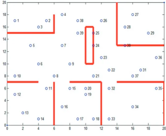
[image:5.544.132.401.268.489.2]temperature sensors. Blue circles denote sensors, red lines represent obstacles and their physical locations.
Figure 2: Dataset(|n|=39).
Temperature values of sensors are shown in Table 1 which illustrates the distribution of temperature values over the study region. Note that the dataset was created based on the fact that the room temperature is not constant in the room due to inconsistent direct and indirect sun light and also air-conditioning in some closed rooms and areas.
Table 1: Sensor values of dataset (Sensor: sensor ID, Temp: temperature in celsius).
Sensor Temp Sensor Temp Sensor Temp Sensor Temp Sensor Temp
1 30 2 31 3 30 4 31 5 32
6 31 7 32 8 30 9 31 10 32
11 26 12 25 13 25 14 25 15 27
16 28 17 27 18 27 19 28 20 27
21 30 22 31 23 31 24 30 25 31
26 32 27 36 28 35 29 36 30 34
31 30 32 32 33 31 34 32 35 33
36 31 37 31 38 32 39 31
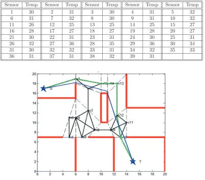
Figure 3: MAKLINK Dij-ACO shortest path with the dataset.
4.2
Validation Measures
The error analysis is carried out between actual sample and interpolated observation values by three statistical methods: the Root-Mean-Square Error (RMSE), the Mean Absolute Error (MAE) and Index of Agreementd(higherdvalue) to describe average model-performance error are examined. Lower MAE and RMSE values and higherdvalue are for better performance.
RMSE is used to measure the success rate of numeric prediction. It is a significant statistical method for error analysis that is the square root of the square of the difference between estimated point and interpolated point, the mathematic formula is as follows:
RM SE=
n
i=1(xi−yi)2
n , (3)
wherexi is the value of i-th point in sample setX,yi is the value of y-th point in sample set
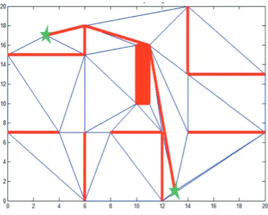
Figure 4: CDT shortest path with the dataset.
Figure 5: A* shortest path with the dataset.
MAE is another significant statistical method for error analysis. MAE is a quantity used to measure how close forecasts or predictions are to the eventual outcomes. The mathematic formula is as follows:
M AE = 1
n n
i=1
|xi−yi|, (4)
where xi is the value ofi-th point in sample setX, yi is the value ofy-th point in sample set
Y, nis the total number of sample points inX andY.
[image:7.544.137.399.323.506.2]degree between actual sample value and interpolated data value.
d= 1−[
n
i=1(xi−yi)2
n
i=1(|xi−μs|+|yi−μs|)2], (5)
where xi is the value of i-th point in sample setX, yi is the value ofi-th point in sample set
Y,nis the total number of sample points inX andY. μs is the mean of the estimated point values. Thedis a dimensionless parameter that varies from 0 to 1.
4.3
Experimental Results
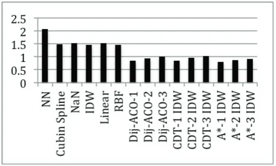
[image:8.544.131.410.286.454.2]Three statistical methods are used for comparison of accuracy, including RMSE, MAE and higher d value. Lower RMSE and MAE values and higher value of d are used for better performance. Six existing interpolation methods (NN, Cubic Spline, NaN, IDW, Linear, RBF) are selected to compare with Dij-ACO-IDW, CDT-IDW and A*-IDW. Three values of neighbors were utilized for IDW namely 1, 2 and 3. For instance, Dij-ACO-1 IDW means that Dijstras shortest algorithm is combined with ACO with the first nearest neighbor of IDW.
Figure 6: Bar chart of RMSE values.
Figure 7: Bar chart of AME values.
Figure 8: Bar chart of Index of Agreementdvalues.
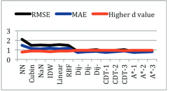
well. Figure 9 summarizes performance measures with a line graph. Individually, comparing among CDT, Dij-ACO and A*, in RMSE, MAE and higher d value statistics, A* with IDW obtains the best accuracy. Dij-ACO with IDW is better than CDT with IDW.
5
Final Remarks
[image:9.544.129.407.272.443.2]Figure 9: Line graphs of RMSE, MAE, and Index of Agreementdvalues.
display interesting findings, and demonstrate the superiority of our approaches over traditional approaches. Various error measures verify our obstacle handling methods outperform tradi-tional non-obstacle handing approaches. Statistical validation verifies the overall performance improvement is significant with 99% of confidence with our dataset. However, more compre-hensive experiments are required to confirm this. Current study could be expanded into few directions. First, one needs more experiments with various urban environmental sensing set-tings. Also, it needs to include various types of obstacles not only physical linear obstacles, but complex arbitrary shaped obstacles. Second, a continuous map generation based on obstacle interpolation would generate an interesting and useful knowledge base that could be used for various decision-making. Third, extensions of obstacle handing interpolation to other inter-polation methods such as areal stealing interinter-polation and kriging are the next step to move forward.
References
[1] P. A. Burrough and R. A. McDonnell. Oxford University Press, 1998.
[2] D. J. Brus, J. J. De Gruijter, B. A. Marsman, R. Visschers, A. K. Bregt, A. Breeuwsma, and J. Bouma. The performance of spatial interpolation methods and choropleth maps to estimate properties at points: A soil survey case study. Environmetrics, 7(1):1–16, 1996.
[3] S. Chen and S. Smith. Commonality and genetic algorithms. Technical Report CMU-RI-TR-96-27, Carnegie Mellon University, 1996.
[4] F. C. Collins and P. V. Bolstad. A comparison of spatial interpolation techniques in temper-ature estimation. In Proceedings of the Third International Conference on Integrating GIS and Environmental Modeling, Santa Fe, NM, Santa Barbara, CA, 1996.
[5] G. di Caro and M. Dorigo. Antnet: Distributed stigmergetic control for communications networks.
Journal of Artificial Intelligence Research, 9:317–365, 1998.
[6] E. Dijkstra and J. M. Thomas. An interview with edsger w. dijkstra. Communications of the ACM, 53(8):41–47, 2010.
[7] M. Dorigo, V. Maniezzo, and A. Colomi. Ant system: Optimization by a colony of cooperating agents. IEEE Transactions on SMC, 26(1):8–41, 1996.
[9] L. D. Floriani and E. Puppo. Constrained delaunay for multiresolution surface description. In Proceedings of the 9th International Conference on Pattern Recognition, pages 566–569, 1988. [10] M. K. Habib and H. Asama. Efficient method to generate collision free paths for autonomous mobile
robot based on new free space structuring approach. InProceedings of IEEE/RSJ International Workshop on Intelligent Robots and Systems, pages 563–567, 1991.
[11] P. E. Hart, N. J. Nilsson, and B. Raphael. A formal basis for the heuristic determination of minimum cost paths. IEEE Transactions on Systems Science and Cybernetics, 4(2):100–107, 1968.
[12] E. Hosseini, J. Gallichand, and J. Caron. Comparison of several interpolators for smoothing hydraulic conductivity data in south west iran. In American Society of Agricultural Engineers, volume 36, pages 1687–1693, 1993.
[13] E. H. Isaaks and R. M. Srivastava. Applied Geostatistics. Oxford University Press, 1998.
[14] G. M. Laslett, A. B. McBratney, P. J. Pahl, and M. F. Hutchinson. Comparison of several spatial prediction methods for soil ph. Journal of Soil Science, 38:325–341, 1987.
[15] F. De Rienzo, P. Oreste, and S. Pelizza. Subsurface geological-ggotechnical modeling to sustain underground civil planning. Eigineering Geology, 96(1):187–204, 2008.
[16] B. D. Ripley. Spatial Statistics. Wiley & Sons, 1981.