M u ltic o m p u te r s
G a v in C o n s ta n tin e M ic h a e l
A thesis submitted for the degree of
Doctor of Philosophy of
The Australian National University
Except where otherwise indicated, this thesis is my own original work.
This thesis considers problems in process and data partitioning when compiling programs for distributed-memory parallel computers (or multicomputers). These partitions may be specified by the user through the use of language constructs, or automatically determined by the compiler.
Data and process partitioning techniques are developed for two models of compilation. The first compilation model focusses on the loop nests present in a serial program. Executing the iterations of these loop nests in parallel accounts for a significant amount of the parallelism which can be exploited in these programs. The parallelism is exploited by applying a set of transformations to the loop nests. The iterations of the transformed loop nests are in a form which can be readily distributed amongst the processors of a multicomputer. The manner in which the arrays, referenced within these loop nests, are partitioned between the processors is determined by the distribution of the loop iterations. The second compilation model is based on the data parallel paradigm, in which operations are applied to many different data items collectively. High Performance Fortran is used as an example of this paradigm.
Novel collective communication routines are developed, and are applied to provide the communication associated with the data partitions for both com pilation models. Furthermore, it is shown that by using these routines the communication associated with partitioning data on a multicomputer is greatly simplified. These routines are developed as part of this thesis.
A c k n o w le d g e m e n ts
I should like to express my indebtedness and great appreciation to the following people who have helped during the execution of the work reported in this thesis...
T o Richard Brent, Brian Molinari and Robin Stanton for their encouragement and counsel.
T o Chris Johnson, Brendan McKay, John Zigman for their fruitful discussions and advice.
T o Peter Bailey, Trevor Vickers and Emma Yarrow for their comments on various drafts.
T o Sally Begg and Kath Read for administrative assistance.
T o David Hawking, David Walsh and the programming staff for technical as sistance.
A b stract iii
A ck n ow led gem en ts iv
C on ten ts v
F igures viii
G lossary o f sym b ols x
C hap ter 1: In tro d u ctio n 2
1.1 Compilation for m ulticom puters... 2
1.2 Research program m e... 3
1.3 Thesis stru c tu re ... 4
C hap ter 2: C om p ilers for m u ltico m p u ters 6 2.1 Parallel architectures and exploiting parallelism ... 6
2.1.1 Parallel architectures... 7
2.1.2 Moving information a r o u n d ... 9
2.1.3 Exploiting p a ra lle lism ... 9
2.2 Restructuring c o m p ile rs... 10
2.2.1 Loop transformation and restru ctu rin g ... 11
2.2.2 General program transform ations... 12
2.2.3 Restructuring programs for m ulticom puters... 13
2.2.4 Case studies... 14
2.3 Multicomputer compilers ... 15
2.3.1 Transformation driven c o m p ile rs ... 16
2.3.2 Language driven compilers ... 17
2.3.3 Analysis driven c o m p ile rs... 19
Contents VI
C h a p te r 3: C o m m u n ic a tio n ro u tin e s 22
3.1 Fujitsu AP1000 arch itectu re... 22
3.1.1 System configuration... 22
3.1.2 Cell a rc h ite c tu re ... 24
3.2 Stride message tra n sfe r... 25
3.2.1 Addressing elements of a two-dimensional a r r a y ... 25
3.2.2 Stride message transfer o p eratio n ... 27
3.3 Collective communication r o u ti n e s ... 30
3.3.1 Generalised addressing of array elem ents... 32
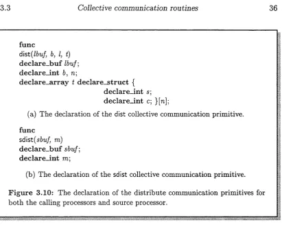
3.3.2 Distribute collective communication ro u tin e ... 35
3.3.3 Concatenate collective communication routine... 40
C h a p te r 4: Im p lic it d a ta p a rtitio n in g 47 4.1 Loop s t r u c t u r e ... 47
4.1.1 The iteration sp a c e ... 48
4.1.2 Array access function ... 50
4.2 Tiling loop iteration s p a c e ... 51
4.2.1 Normalising the loop n e s t ... 51
4.2.2 Deriving the tile s p a c e ... 52
4.2.3 Allocating tiles to p ro c e s s o rs ... 55
4.2.4 Allocating iterations to p ro c e ss o rs ... 56
4.3 Implicit data distribution and retriev al... 57
4.3.1 Determining the array read s e t ... 60
4.3.2 Deriving the array receive p a rtitio n ... 63
4.3.3 Determining the array write s e t ... 66
4.3.4 Deriving the array send p a rtitio n ... 68
C h a p te r 5: E x p licit d a ta d is trib u tio n : th e H PF d irectiv es 71 5.1 Data distribution m o d e l... 72
5.2 The align d ire c tiv e ... 73
5.2.1 Exact match ... 73
5.2.2 Intra-dimension alignm ent... 74
5.2.3 Inter-dimension alignm ent... 75
5.3 The processors d ire c tiv e ... 75
5.4 The distribute d i r e c tiv e ... 76
5.4.1 Cyclic distribution f o r m a t... 77
5.4.2 Block distribution f o r m a t ... 78
5.4.3 * distribution fo rm a t... 80
5.5 Explicit data d is tr ib u tio n ... 80
5.5.1 Allocating array data to abstract processors... 81
5.5.2 Allocating abstract processors to the target multicomputer . . . 84
5.5.3 Allocating array data to physical processors... 88
C h a p te r 6: E x p e rim e n ta l re s u lts 96
6.1 Structure of the experimental com piler... 97
6.2 Performance study method ... 99
6.2.1 Performance m easurem ent... 99
6.2.2 Analysis and comparison ... 100
6.3 Automatic data partitioning resu lts... 100
6.3.1 Matrix m u ltip lic a tio n ... 100
6.3.2 Computation of the Mandelbrot f r a c t a l ...104
6.4 NCAR Community Climate M o d e l...108
6.4.1 Brief overview of the m o d e l... 109
6.4.2 Parallel implementation of the m odel...109
6.4.3 Analysis of the parallel m o d e l... I l l C h a p te r 7: C onclusions 115 7.1 Future re s e a rc h ...115
7.2 The contributions of this t h e s i s ... 116
A p p e n d ix A: M em o ry space a llo c atio n fu n ctio n 120 A p p e n d ix B: C o m m u n ic atio n o p e ra tio n s specification 123 B.l Distribute communication ro u tin e... 123
B. 2 Concatenate communication r o u t i n e ... 125
A p p e n d ix C: P se u d o co d e d e sc rip tio n 127 C. l Declaration of variables ...127
C.1.1 I n te g e r s ...127
C.1.2 Single dimension a r r a y s ... 128
C .l.3 S tru ctu res... 128
C .l.4 Buffers... 128
C.2 L o o p s ...129
C.3 Conditional Statements ...130
C. 4 Declaring r o u t i n e s ... 130
A p p e n d ix D: S y n ta x of th e H P F d irectiv es 132 D. l The distribute d ir e c tiv e ...132
D.2 The align d ire c tiv e ... 134
D. 3 The processors d ire c tiv e ...135
A p p e n d ix E: A co m p iler g e n e ra te d p ro g ra m 136 E . l Host p ro g ra m ... 136
E.2 Host lib r a r y ... 136
E.3 Cell p r o g r a m ... 137
E.4 Cell l i b r a r y ... 137
F ig u re s
2.1 Parallel computer a rc h itec tu re s... 7
3.1 Fujitsu AP1000 system desig n ... 23
3.2 Fujitsu A P I000 cell architecture ... 24
3.3 Layouts for a two-dimensional a r r a y ... 26
3.4 Access pattern for the stride message transfer o p e r a tio n ... 28
3.5 Stride message transfer o p e ra tio n ... 29
3.6 Function sdma ... 30
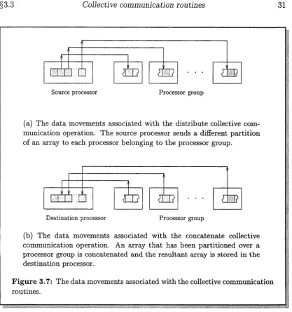
3.7 Data movements associated with collective communication ro u tin es... 31
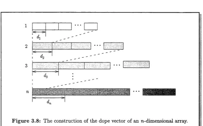
3.8 Dope vector of an rc-dimensional a r r a y ... 33
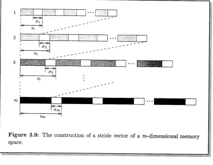
3.9 Stride vector of a m-dimensional memory s p a c e ... 35
3.10 Declaration of the distribute communication r o u t i n e ... 36
3.11 Examples of the distribute collective communication ro u tin e ... 37
3.12 Function d i s t ... 39
3.13 Declaration of the concatenate communication p rim itiv e ... 41
3.14 Examples of concatenate collective communication ro u tin e ... 42
3.15 Function d c o n c a t... 45
4.1 Perfectly nested loop n e s t ... 48
4.2 Example perfectly nested loop n e s t ... 49
4.3 Normalised loop n e s t ... 52
4.4 Tiled loop n e s t ... 53
4.5 Example tiled loop n e s t ... 54
4.6 Partition of a tiled loop nest executed by a processor... 55
4.7 Example partition of a tiled loop nest executed by a processor ... 56
4.8 Allocation of loop iterations to p ro c e sso rs... 57
4.9 Array reference enclosed in a tiled loop nest... 58
4.10 Tiled and partitioned iteration and data s p a c e s ... 59
4.11 Array reference enclosed in a partition of a tiled loop n e s t ... 62
4.12 Partitioning array data ... 66
4.13 Retrieving modified array d a t a ... 70
5.1 HPF Data Distribution M odel... 72
5.2 Example CYCLIC array d is trib u tio n ... 78
5 . 3 Example BLOCK array d i s t r i b u t i o n... 7 9 5.4 HPF code fragment involving distribute directives... 82
5.5 Block index set resulting from a HPF distribution... 83
5.6 Allocation of abstract processors to physical processors... 86
5.7 Example allocation of abstract processors onto physical p ro c e ss o rs ... 87
5.8 Allocation of array data to physical processors ... 88
5.9 HPF code fragment involving the align and distribute directives... 92
5.10 Transformation of the source array data sp ace... 95
6.1 Architecture of the experimental c o m p ile r... 98
6.2 Execution times for matrix m u ltip lica tio n ...102
6.3 Performance of matrix multiplication ... 103
6.4 Execution times for Mandelbrot fractal... 106
6.5 Performance of Mandelbrot fractal p ro g ra m ...107
6.6 Decomposition of the CCM1 d o m a in ... 110
6.7 Execution times for the NCAR CCM1 ... 112
G lo s s a ry o f sy m b o ls
G e n e r a l S p a c e s R
R n Z Z n
T h e set o f all real n u m b ers
T h e set o f all n -d im e n sio n a l rea l vectors T h e set o f all n a tu r a l n u m b ers (in c lu d in g 0) T h e set o f all n -d im e n sio n a l in te g e r vectors L o g i c a l r e l a t i o n s
a => b a V b a A b 3 a V a
a im plies 6; b if a; a only if b a or b
a a n d b
T h e re e x ists a n a For all a
S e t s { a , 6 , c } 0 a £ B A H B A C B
{ a e X | P ( a ) }
A set c o n ta in in g a, b a n d c T h e e m p t y s e t, {}
a is a n e le m en t of B A in te rse c tio n B A is a s u b s e t of B
T h e s u b s e t o f th e se t X sa tisfy in g th e p ro p e rty P F u n c t i o n s
T \ X -> Y T ~ l one-to-one
A fu n c tio n T a ssig n in g a value in Y to every elem ent in T h e inverse of T \ T ~ l : Y —> X
T is one to one if a n d only if T ( a ) is different for every value of a; T ( x ) = T ( y ) => x = y.
G en eral op erators
n
E
V ector op erators a
0 1 a < b a / 6 a * b a — b a 4" b a ■ b a div b a mod b
a _b_
a ' b
Product Sum
The n-dimensional vector (ai , <22,..., a n )
The n-dimensional vector ( 0 , 0 , . . . , 0) The n-dimensional vector ( 1 , 1 , . . . , 1) a i < &i A 02 < bo A . . . A a n < bn
A 0-2 ~f~^2 A . . . A CLji bn
(a \6i, 0 2 ^ 2 , . . . , a n bn )
(ai — &i, Ü2 — 62,. • •, an — &„) (ai 4- 61, 02 4- ^25 • • • 5 an 4- bn) (di b\ 4- a262 + . . . 4- 0Ln bn)
1
I n tr o d u c tio n
1.1
C o m p ila tio n for m u ltic o m p u te r s
Multiprocessor systems are classified into two categories, namely shared-memory parallel computers (or multiprocessors) and distributed-memory parallel com puters (multicomputers). Multiprocessors provide all processors with uniform access to a common global memory. The Alliant FX/2800, the Sequent Balance [122], the Cedar [76] and the IBM RP3 [102] are examples of multiprocessors. In a multicomputer the memory is distributed among the processors, each of which has access only to its local component. For example, the Connection Machine CM-5 [124], the IBM SPl, the IBM SP2 and the Fujitsu AP1000 [64] are all multicomputers.
In the context of building massively parallel systems, multicomputers offer an advantage in terms of cost and scalability. When the system size grows the system does not suffer from the memory contention as in large multiprocessors be cause the physical memory modules are local to the processors. However, writing efficient programs for multicomputers is a great challenge for the programmer.
The following issues arise in programming multicomputers:
• Process partitioning: parallelism must be made explicit in the program. This involves breaking a computation into a collection of tasks which are assigned to different processors and executed in parallel.
• Data partitioning: since there is no global memory on a multicomputer, the data structures (such as arrays) in a program must be partitioned and distributed to the processors.
• Communication and coordination: the distributed tasks in a parallel com putation generally need to share data or synchronise with each other.
§1.2 Research program m e 3
The naive approach to programming multicomputers involves programming each processor with a conventional language, such as C or Fortran, using explicit communication commands in the program for sending and receiving messages. There are at least two difficulties associated with this approach: (1) machine ef ficiency may be very low if the computation is dominated by communication and synchronisation: and (2) the user is forced to manually partition processes and data, explicitly manage communication among processes and be aware of all data movements in the program. The advantage of this approach is that the program ming model matches the machine architecture, requiring the implementation of fewr new compilation techniques. Almost all commercial multicomputers support this approach. For example, C and Fortran with message passing primitives are available on the Fujitsu AP1000 and the Connection Machine CM-5.
One approach to overcoming the difficulties associated with programming a multicomputer is to emulate a shared-memory facility, known as virtual shared memory [2, 16, 24, 28, 32, 67, 82, 87]. However the overhead of supporting such a virtual shared memory, especially when the multicomputer consists of a large number of processors, may greatly offset the benefits of this solution.
Another approach to programming multicomputers employs a compiler to do much of the work. The mechanisms by which parallelism is achieved are either explicit or implicit. Implicit parallelism relies on the compiler to automatically uncover and exploit parallelism through comprehensive analysis of the structures inherent in serial computations. Explicit parallelism requires the user to invoke the parallelism in a computation through the use of some language construct.
The compiler generates an appropriate parallel program for the target mul ticomputer. For most compilers this parallel program corresponds to the single program multiple data (SPMD) model [66], where all processors execute the same program but operate on distinct data items. The user is relieved of the bur den of generating explicit message passing primitives. Research efforts include the Fortran D compiler [57, 58], Superb [131], Parafrase-2 [105, 106] and High Performance Fortran (HPF) [53]. Commercially available compilers for multicom puters which use this approach include MIMDizer [117] and Aspar [62].
The compilation approach to programming multicomputers can be viewed as a means of restructuring existing sequential programs into a form more amenable to multicomputer architectures, as well as encouraging the development of new programs. However, questions related to compilation techniques for multicom puters are still largely unanswered. The many challenges and promises of the compilation approach are the motivations for this thesis.
1.2
R esearch program m e
experimental context for this thesis is the development of a compiler for the Fujitsu AP1000 multicomputer.
To this end two models of compilation for multicomputers are examined. The first compilation model focusses on the loop nests present in a serial program. Executing the iterations of these loop nests in parallel accounts for a significant amount of the parallelism which can be exploited in these programs. The par allelism is exploited by applying a set of transformations to the loop nests. The iterations of the transformed loop nests are in a form which can be readily dis tributed amongst the processors of a multicomputer. The manner in which the arrays, referenced within these loop nests, are partitioned between the processors is determined by the distribution of the loop iterations. The second compilation model is based on the data parallel paradigm, in which operations are applied to many different data items collectively. High Performance Fortran is used as an example of this paradigm. HPF provides the user with explicit control over the data partitioning utilising data alignment and distribution compiler directives.
Collective communication routines are developed, and are applied to provide the communication associated with the data partitions for both compilation mod els.
1.3
T h e s is str u c tu r e
The body of this thesis is divided into seven chapters.
• Chapter 2 discusses previous work of relevance to the development of tech niques for programming multicomputers. The discussion focusses on par allel language models, restructuring compilers and compilers developed specifically for multicomputers. Several major research projects are de scribed.
• In chapter 3, the collective communication routines distribute and concat enate are introduced. These form the basis of the data partitioning methods outlined in the subsequent chapters of this thesis. A new message handling mode for the Fujitsu AP1000, called stride message transfer This message handling mode subsequently supports the implementation of the collective communication routines on the Fujitsu AP1000. An overview of the ar chitecture of the Fujitsu AP1000 together with the implementation of the collective communication routines on this multicomputer is incorporated in this discussion.
§1.3 Thesis structure 5
that it is possible to retrieve these elements back into a single array by a single operation using the collective communication routine concatenate. • The High Performance Fortran (HPF) data distribution model is introduced
in chapter 5. The focus of this discussion is the implementation of this model using the distribute collective communication routine. A new meth odology for analysing the HPF alignment and distribute compiler directives is developed. This methodology is then used to implement the HPF data distribution model on the Fujitsu AP1000.
• Chapter 6 introduces an experimental compiler for the Fujitsu AP1000 which implements the process and data partitioning techniques developed in chapters 4 and 5. The results of a series of test cases, conducted using this compiler, which are designed to demonstrate the effectiveness of these techniques are reported.
This chapter examines alternative approaches to the compilation of programs for multicomputers. A model which establishes the place of such compilation in the wider context of parallel computing is presented in §2.1. Restructuring compilers, designed to automatically transform a sequential program to a semantically equi valent parallel program for a multicomputer, are described in §2.2. A description of compilers developed specifically for multicomputers then follows.
2.1
P a r a lle l a r c h ite c tu r e s an d e x p lo itin g
p a r a lle lism
For descriptive purposes through this chapter the following three layered model has been adopted
Programming model/High level language
Communication model/Low level language
Parallel architecture
Whilst being limited this model is sufficient for the exposition. Compiling pro grams for multicomputers can be viewed as mapping the parallelism exploited in a program, using some high level language, to its implementation on a parallel architecture. The remainder of this section discusses each layer of the model.
§2.1 Parallel architectures and exploiting parallelism 7
Memory
Processors
• • •
Processor interconnect network
□
□
_
I
|
□
r
□
L
□
n
_
1 i • • • □ □ _ I i(a) Architecture of a shared-memory parallel computer or mutlipro- cessor. A single bus is used to connect the processors and memory. Processors often have substantial cahces providing closely coupled private memory.
Processors
Memory
Processor interconnect network
I
□
□
□
□
□
□
. . .□
□
. . .
r
“
n
rr-
-
-
-
nr. —
T
-rr-
-
-
-
-
-
-
-
-
-
-
-
-
-
-
-
-' M em ory in terco n n ect netw ork >
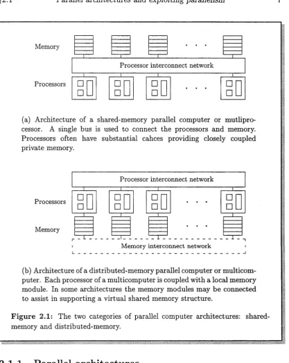
(b) Architecture of a distributed-m emory parallel computer or multicom puter. Each processor of a multicomputer is coupled w ith a local memory module. In some architectures the memory modules may be connected to assist in supporting a virtual shared memory structure.
F igure 2.1: The two categories of parallel computer architectures: shared- memory and distributed-memory.
2 .1 .1 P a r a lle l a r c h ite c tu r e s
In this discussion parallel architecture refers to the method by which the pro cessors and memory are connected to realise the parallel computer. The parallel architecture must be taken into account by the software.
[image:18.537.63.481.68.594.2]no need to explicitly move data from processor to processor. The greatest weak ness of bus-based multiprocessor designs is that the bandwidth of the bus does not scale. As the number of processors increases it becomes more likely that when one processor requires the bus, another will already be using it. This contention is the major limitation of the practical size of based-based multiprocessors. Given current implementation techniques, this limitation leads to a machine of a few tens of processors.
One solution to this single-bus bottleneck is to provide multiple communica tion paths between the processors and memory. A crossbar switch will connect each processor directly with every memory module, so contention is entirely elim inated. This is the most efficient interconnection mechanism. However, the cost of connecting n processors with m memory modules—which can be expressed as a function of the number of cross-points required in the switch—is O(nm), compared with 0(n) for the bus. Hence, the architecture becomes costly to implement as the number of processors increases.
Instead of viewing the close connection between each processor and memory as merely a means of eliminating memory contention, a distributed-memory parallel computer (or multicomputer) uses it as a basic building block. Each processor of multicomputer is coupled with a local memory module. This processor/memory combination is replicated and interconnected by a network. Figure 2.1 schemat ically illustrates a typical multicomputer architecture. Each processor can only directly access its own local memory module. The processors typically com municate and coordinate by transmitting data between senders and receivers. Most frequently this is done by some form of message passing of which there are many different variants (see §2.1.2). As the number of processors in a multicom puter increases it does not suffer from the memory contention present in large multiprocessors because the memory modules are local to the processors. The implementation of this architecture leads to machines comprised of thousands of processors.
Of course, it is also possible to emulate shared memory on a multicomputer, referred to as virtual shared memory. Virtual shared memory masks both the sep arate processor address spaces and the communication between processors, and may be implemented in hardware or software. Systems such as Alewife [24],
§2.1 Parallel architectures and exploiting parallelism 9
2 .1 .2 M o v in g in fo r m a tio n a r o u n d
The processors of a parallel computer cooperate to solve a common task. A pro gram is run as a system of parallel processes, where each process is the execution of a sequential instruction stream and has its own private memory space. Dur ing execution the problem of communication between processes arise. There are wide variety of methods used to support communication between processes. The method chosen inherently reflects the underlying parallel architecture.
In a shared-memory architecture processors communicate via shared data structures. One process updates or writes a data value which is then read by another process. Since several processes may execute simultaneously and require access to the shared data, problems of data coherency arise. These are solved by serialising access to shared data; often managed through a protection mechanism, such as locks, semaphores [34] or critical regions [19], which indicate the data is being accessed by a process. An alternate solution is to adopt a coherent programming model such as monitors [60] or transactions [88, 95].
Processes may only communicate by transmitting data between different mem ories on a distributed-memory machine. In the simplest case, one process sends a message and another process receives it. Many extensions exist which ex pand the number of senders (scatter-gather routines) or receivers (broadcast or multicast routines). Collective communication, one such extension, is defined as communication which involves a group of processes, and is developed in chapter 3. There are a number of alternate mechanisms used to send or receive data. For example, a message may be buffered in the sender or receiver, or the message may be sent synchronously or asynchronously. These mechanisms are addressed and supported in the recent standardisation of a message passing interface for parallel computing (MPI) [94]. Message passing may also be used on top of a shared-memory architecture in order to support particular models of interaction, such as pipelining or client-server systems.
2 .1 .3 E x p lo itin g p a r a lle lis m
The mechanisms by which parallelism is achieved can be either implicit or explicit. Implicit parallelism is used primarily as a technique to gain speedup without user intervention. Typically this is performed at the compilation phase of a se quential program. Compilers which exploit implicit parallelism are known as restructuring compilers. These compilers are based on the premise that the ex ploitable parallelism that scale with the problem size is largely present in loops
(see §2.2).
write parallel programs as no language or compiler support is available. Altern atively, the Linda model [23] provides a global shared memory called the tuple space; processes can read, input and output tuples from the tuple space.
Imperative languages, such as C or Fortran, are probably more widely used for explicit parallel programming than any other language style. Since they were not originally designed as parallel languages, the ability to specify parallel computa tion is achieved by using them with message passing libraries, such as MPI, or by adding parallel extensions to their syntax. Some examples of the latter include C* [51, 52, 111], High Performance Fortran [53] and Fortran D [39, 56, 57, 58]. Numerous compilers which support this model of parallel programming have been developed (see §2.3).
2.2
R e s tr u c tu r in g co m p ilers
The earliest significant research in restructuring compilers is documented in [78, 77, 98, 99]. Restructuring compilers, such as Parafrase-2 [105, 106], PFC [8, 10], Ptran [5] and Parascope [20], transform code written in a conventional programming language into an equivalent program that can be executed on a parallel architecture. This is accomplished using program transformations, based upon dependence analysis [14, 108], to expose and exploit the hidden parallelism present in the input program.
For a transformation to be valid it must preserve the semantics of the pro gram. A dependence is a relationship between two computations that places constraints on their execution. Dependence analysis [14, 129] identifies these re lations, which are then used to determine whether a particular transformation can be applied without changing the semantics of the program. Dependence rela tions can be manipulated as the program is transformed so that the dependences in the transformed program can be obtained from the dependences in the original program.
For a restructuring compiler to apply a transformation to a program, it must do three things:
1. Decide upon a part of the program to transform and an appropriate program transformation to apply;
2. Verify that the transformation does not change the semantics of the pro gram;
3. Transform the program.
§2.2 Restructuring compilers 11
2 .2 .1 L o o p tr a n s fo r m a tio n an d r e s tr u c tu r in g
Loop level parallelism accounts for most parallelism which can be exploited in scientific code by restructuring compilers [29]. Therefore, the major goal of re structuring compilers is to discover and exploit parallelism in loops.
Two iterations of a loop can be executed in parallel in there is no dependence relation from one iteration of the loop to another iteration of the loop. The trans formations discussed in this section are applied to enable the iterations of a loop to be executed in parallel. The transformations discussed here are summarised by Aho et al. [3].
Many of the transformations presented in this section are only applicable to perfectly nested loop nests. A loop nest is perfectly nested if the body of every loop other than the innermost loop consists of only the next loop in the nest (see §4.1).
L o o p in te r c h a n g e
Loop interchange exchanges the position of two loops in a perfectly nested loop, generally moving one of the outer loops to the innermost position [10, 9, 129]. Interchange is one of the most powerful of the loop transformations because it can enable vectorisation or parallelisation of a loop nest.
L o o p sk e w in g
Loop skewing is an enabling transformation that is primarily useful in combina tion with loop interchange [80, 96, 129]. Loop skewing is used to handle wavefront computations, so called because the updates of the array propagate like a wave across the iteration space.
An alternative method for handling wavefront computations is supernode par titioning [63].
S tr ip m in in g
Strip mining is a method of adjusting the granularity of an operation [1, 7, 89]. One of the most common uses of strip mining is to choose the number of inde pendent computations in the innermost loop of a nest.
L o o p tilin g
L oop d istr ib u tio n
Loop distribution (also known as loop fission or loop splitting) breaks a single loop into many. Each of the new loops has the same iteration space as the original loop, but contains a subset of the statements present in the original loop [75, 96]. Loop distribution may used to create a perfectly nested loop nest, to which other distributions (such as loop interchange) may be applied.
L oop u n ro llin g
Loop unrolling replicates the body of a loop n times and iterates by step n instead of 1. It is a fundamental technique for exploiting instruction level parallelism. Most restructuring compilers unroll the innermost loop of a loop nest.
L oop co a lesc in g
Loop coalescing combines a loop nest into a single loop [104]. It used primarily to improve the scheduling of a loop on a parallel machine.
L oop n o r m a lisa tio n
Loop normalisation converts all loops so that the iterations start at one (or zero) and are incremented by one [10]. The most important use of normalisation is to permit the compiler to apply other transformations that may require normalised iteration ranges.
L oop sp rea d in g
Spreading takes two serial loops and moves some of the computation from the second to the first so that the bodies of both loops can be executed in parallel [49].
S calar e x p a n sio n
Loops often contain variables that are used as temporaries within the loop body. Such variables create a dependence relation that prevents the loop being paral lelised. Allocating one temporary for each iteration removes the dependence and makes the loop a candidate for parallelisation [98, 129].
2 .2 .2 G e n e r a l p r o g r a m tr a n s fo r m a tio n s
§2.2 Restructuring compilers 13
C o n s t a n t p r o p a g a tio n
Constant propagation [21, 128] is one of the most important transformations that a restructuring compiler can perform. Typically programs contain many constants; by propagating them through the program, the compiler can do a signi ficant amount of precomputation. More important, the propagation reveals many opportunities where other transformations can be applied. For example, loops may contain constants in their bounds which can be eliminated using constant propagation. These may then be transformed using transformations outlined in
§2.2.1.
P r o c e d u r e in lin in g
Procedure inlining replaces a procedure call with a copy of the body of the called procedure [6, 13, 118]. Each occurences of a formal parameter is replaced with a version of the corresponding actual parameter. When a procedure is inlined, all overhead for the invocation is eliminated. More importantly it improves compiler analysis. In many circumstances a loop containing a procedure call cannot be parallelised because its behaviour is unknown. After the procedure is inlined the behaviour of the loop can be analysed and if possible parallelised.
An alternative to inlining is to perform interprocedural analysis. The ad vantage of interprocedural analysis is that it can be applied uniformly, since it does not cause code expansion the way inlining does. However, interprocedural analysis significantly increases the complexity of the restructuring compiler.
2 .2 .3 R e s t r u c t u r in g p r o g r a m s for m u ltic o m p u te r s
Restructuring compilers can assist the programming process on multicomputers. Clearly, the main goal of restructuring compilers is to detect and exploit hidden parallelism present in a program. On multicomputers non-local memory access costs are much higher than those for local memory. This must be taken into account when applying the transformations of the type present in restructuring compilers to programs for multicomputers.
Compilation techniques have been developed to improve data locality. These techniques can enhance temporal and spatial locality of scientific codes. The ex ploitation of parallel loops, detected using data dependence analysis, combined with these data locality optimisations is an effective approach to compiling pro grams for multicomputers.
Though this compilation approach effectively reduces non-local memory ac cesses, some limitations still persist. Such an approach has proven inefficient because the resulting data partition may be highly complex and may frequently change between loop nests. Additionally, no compiler support is provided for generating or optimising the required communication. These problems are ad dressed in chapter 4 using the collective communication operations developed in chapter 3.
2.2.4
C ase s tu d ie s
Parafrase-2 and PFC are discussed to illustrate the use of program transformations in restructuring compilers.
P a r a f r a s e - 2
Parafrase-2 was the first restructuring compiler to address the problem of sys tematically transforming sequential Fortran programs into parallel programs for a variety of architectures. These architectures include register-to-register and memory-to-memory vector processors, array processors and shared-memory ma chines.
Parafrase-2 is organised a series of passes through the input program. Each pass applies some program transformation. These passes are assembled into a sequence by the user. When applied to a Fortran program Parafrase-2 yields a semantically equivalent parallel program. Altering the sequence of these passes allows the resulting program to be tailored to a specific architecture.
Parafrase-2 performs comprehensive data dependence analysis, primarily the GCD and Banerjee tests [14], on the input program to detect hidden parallel ism. A series of transformations are then applied to create the final program. These transformations are classified into three classes: architecture independent transformations, intermediate transformations and machine dependent trans formations.
• Architecture independent transformations do not require any knowledge of the target architecture. These include scalar dataflow analysis, scalar renaming, scalar expansion and subroutine expansion.
• The intermediate transformations adapt the program to the requirements of the target architecture ignoring the specific attributes of the target machine. • The machine dependent transformations adapt the program to the require
ments of the target machine.
§2.3 Multicomputer compilers 15
PFC
PFC (Parallel Fortran Converter) is an automatic source-to-source vectoriser de signed to translate Fortran 77 into Fortran 8x. PFC was initially based on Parafrase.
PFC initially transforms the input program into an internal representation which is essentially based upon an abstract syntax tree and the associated symbol table. Each transformation performed by PFC manipulates this internal repres entation.
PFC transforms the input program into the final program in four steps, where each step consists of one or more passes over the program.
• Step one: interprocedural analysis is performed; the call graph is construc ted.
• Step two: standard transformations are applied; These include if-conversion, do-loop normalisation, induction variable recognition and substitution, for ward substitution, constant propagation, and recognition and deletion of dead code.
• Step three: dependence analysis is performed; dependence analysis applies the separability, GCD and Banerjee tests (the latter with an adaptation for triangular loops).
• Step four: vector code is generated; scalar expansion and renaming, and loop interchange have been built into the code generator.
2.3
M u ltic o m p u te r co m p ilers
Compilation techniques for multicomputers start much later than the efforts tar geted at restructuring compilers [22, 30, 112, 131]. Multicomputer compilers achieve performance through the compile-time optimisation of both parallelism and interprocessor communication. For the purposes of this discussion they are classified as follows:
• Transformation driven: First generation systems that perform optimising transformations on naive run-time resolution code.
• Language driven: Aspects of multicomputer architectures can be modelled by extending a standard programming language. These extensions per mit the programmer to formulate parallel algorithms explicitly. Language driven systems rely on the language extensions to guide the compilation and optimisation process.
It should be noted that such a classification is fluid. A number of systems are evolving, including simple language translators and complex tools that perform impressive compile-time analysis and optimisations. The following sections de scribe compilers representative of each of these groups.
HPF has been adopted as a defacto standard by many researchers developing multicomputer compilers. Therefore, it is used throughout this section as a point of comparison with the compilers presented.
2 .3 .1 T r a n s fo r m a tio n d r iv e n c o m p ile r s
The earliest multicomputer compilers are Superb and Id Nouvea. These compilers perform extensive compile-time analysis but adopt a rather cumbersome compil ation approach. Both systems first insert guards and element-wise messages to generate a naive program performing run-time resolution.
To produce a more efficient program, transformations are then applied to this naive program. In order to apply these transformations, the compiler must keep track of intermediate program versions. The presence of guards and explicit communication affects the program’s semantics in ways that are difficult to as certain. This is particularly the case in trying to assess whether the application of a program transformation would cause deadlock [48]
S u p e r b
Superb [45, 46, 131] is a semi-automatic parallelisation tool designed for MIMD multicomputers. Each node of the multicomputer contains a pipelined vector unit. Program transformation is performed in two distinct phases. Firstly, the coarse grained parallelism present in the program is determined, and the compu tation partitioned over a set of processors. Secondly, the code for each processor is vectorised. Dependence analysis [14, 129] guides these program transforma tions l .
Superb supports user-specified data distribution, through the use of contigu ous rectangular distributions. Unlike HPF [53], Superb does not support data alignment, cyclic distributions or dynamic data decomposition. Superb origin ated overlaps as a means to both specify and store nonlocal data accesses, and hence avoid locality checks during execution.
Once program analysis and transformation is complete, the necessary com munication is automatically generated and vectorised using data dependence information. Computation is partitioned via explicit guards, which may be elim inated by loop bounds reduction [47]. Superb performs interprocedural data flow analysis of parameter passing. The algorithm is similar to the that used in the Fortran D compiler but less involved, since Superb does not provide dynamic data decomposition.
§2.3 Multicomputer compilers 17
Id N o u v e a
Id Nouvea [103, 110] is a functional language extended with single assignment arrays called I-structures. Simple user specified block data distributions are provided. Send and receive communication primitives are inserted to commu nicate each non-local array access, resulting from the specified data distribution. Global accumulation and reduction operators are supported. The use of the I-structure representation considerably simplifies the program analysis. Unlike other systems, the compiler typically generates a distinct program for each pro cessor.
2 .3 .2 L a n g u a g e d r iv e n c o m p ile r s
Language driven compilers target programs containing explicit parallelism, data distribution and potential user specified communication. Compilation is lim ited to partitioning the computation across the processors, and automatically detecting the communication generated by the resulting process partition. Im plementation of the communication is based on matching language features or on user annotations to routines available in the run time system.
Some of these languages specify parallelism utilising a local view of computa tion, where the user specifies computation for a single data point of the problem, and relies on the compiler and run-time system to replicate this computation for all data points of the problem [51, 115]. Comparatively, HPF supports a global view of computation where the user specifies the entire computation, relying on the compiler to partition the computation across the processors of a multicom puter. This is illustrated in the discussion of developed for HPF in chapter 5.
C ry sta l
Crystal [31, 83, 84, 85, 86] is a high-level function language. As such, the compiler possesses significantly different program analysis techniques from those used for compiling imperative languages such as Fortran. The compiler performs compile time analysis and optimisation that pioneered both automatic data decomposition and techniques for collective communication generation.
K a li
Kali [68, 69, 71, 72, 73, 93] is a Fortran based language. The compiler developed for Kali was the first system to support both regular and irregular computations on MIMD multicomputers. The user of the Kali system specifies the following information: the processor array on which the program is to be executed; the distribution of the data structures across these processors, using block, cyclic or user specified arbitrary distributions; and the parallel loops and their decompos ition onto the processor array. Interprocessor communication is then generated automatically based on the parallel loop and data decompositions.
C M F o r t r a n
CM Fortran [4, 123] is an implementation of Fortran 77 extended with vector notation, data layout and alignment specification. The user explicitly specifies data-parallelism via array assignments and the f o r a l l loop construct. The compiler distributes the data arrays and generates communications. It also automatically aligns arrays based on the analysis of the usage patterns of ar ray occurrences. The compiler relies heavily on the underlying SIMD architecture of the Connection Machine, and hence does not address many issues that are critical to MIMD computers.
F o r t r a n D
Fortran D [39, 56, 57, 58] is a version of Fortran 77 augmented with powerful data decomposition specifications. The decomposition statement is used to declare a problem domain for each computation; the align statement is used to specify how arrays should be aligned with respect to one another; and the distribute statement is used to map the problem and its associated arrays to the phys ical machine. Fortran D is designed to provide an efficient machine-independent parallel programming model.
C *
C* [51, 52, 111] is an extensions of C that supports SIMD data parallel programs. It provides a local view of the computation. The only mechanism by which par allelism is achieved is through the simultaneous application of a single operation to an entire data set. Parallel computations are specified as actions on a domain. Data is described as either mono (local) or poly (distributed). There are no align ment or distribution specifications. The compiler automatically determines the data decomposition and generates the associated interprocessor communication.
§2.3 Multicomputer compilers 19
DINO
DINO [113, 114] is a C-like explicit parallel language. The goal of DINO has been to simplify programming parallel numerical algorithms for multicomputers without hindering efficiency. Like C*, it provides the user with a local view of the computation. A construct called an environment is used to represent an abstract parallel machine. The compiler generates multiple processes per physical processor when large numbers of virtual processors are declared in the environment. Parallel computations are specified via composite functions.
The DINO system requires the user to explicitly specify the array distribu tions. DINO supports block, cyclic and stencil-based distributions with overlaps, but provides no alignment specifications. Nonlocal memory accesses resulting from the data distribution must be annotated by the user. The DINO compiler translates these references into communications. Special language constructs are provided for reductions.
DINO is a powerful and flexible language. It can be used to specify optimisa tions such as coarse grain pipelining and iteration reordering for pipelined and parallel computations [97]. However, its many features may prove burdensome to users. DIN02 has been proposed to address this problem. It provides a large set of additional language features to support parallel task creation, data and computation decomposition, synchronisation and communication.
PARTI and ARF
PARTI [116] is a set of run-time library routines that support irregular computa tions on MIMD multicomputer architectures. PARTI is the first system to propose and implement user specified irregular decompositions, and uses a hash code to support non-local memory accesses.
ARF [70, 130] provides a Fortran interface for accessing PARTI run-time rout ines. The ARF compiler provides block and cyclic distributions, and is the first compiler to support user specified irregular decompositions. The goal of ARF is to demonstrate that inspector/executors can be automatically generated by the compiler for user specified parallel loops.
2.3.3
A n aly sis d riv e n c o m p ile rs
Analysis driven compilers rely heavily on compile-time analysis rather than lan guage features or user annotations to exploit parallelism in a program. Typically they accept Fortran 77 or Fortran 90 programs with data decomposition annota tions, and perform extensive program analysis to automatically detect parallel operations.
such as local loop bounds, array indices, and the data to communicate. As the burden on the compiler is reduced by this approach, the compiler has greater flexibility allowing it to handle complex cases such as work arrays or array re shaping at run-time. However, it does limit the extent of the optimisation th at can be applied at compile-time for simple computations.
M IM D iz e r
MIMDizer[117] is an interactive parallelisation system for multicomputers. It performs data-flow and dependence analyses, and also supports powerful loop level transformations. Associated tools graphically display call graph, control flow dependence and profiling information.
Users may interactively select block or cyclic distributions for selected array dimensions. Parallelism in loops is exploited by applying code spreading. This can be done interactively or automatically. Distributed arrays are linearised in order to simplify ownership computations at run-time. MIMDizer automatically gener ates communications resulting from nonlocal memory accesses at the conclusion of the parallelisation process.
V ie n n a F ortran
Superb has been adapted for a new language called Vienna Fortran [27]. Vienna Fortran provides data alignment and distribution specifications similar to HPF. It supports explicit processor array declarations, irregular computations, perform ance estimation and automatic data decomposition [18, 25, 37]. Dynamic data decomposition is permitted.
Vienna Fortran allows the user to specify additional attributes for each dis tributed array [26]. Restore forces an array to be restored to its original decom position at the start of a procedure. Notransfer causes this remapping to be performed logically, rather than copying the values in the array. Nocopy guar antees that the procedure’s formal and actual parameters have the same data decomposition. This type of attribute not found in the HPF data distribution model.
A L , iW arp
§2.3 Multicomputer compilers 21
3
C o m m u n ic a tio n ro u tin e s
This chapter establishes the machine-level context for the data partitioning tech niques developed in this thesis. Section 3.1 presents and overview of the ar chitecture of the Fujitsu AP1000 experimental multicomputer. A new message handling mode, called stride message transfer, is developed to support new col lective communication routines and is described in detail in §3.2. New collective communication routines distribute and concatenate, used to realise the data par titioning techniques presented in chapters 4 and 5, are introduced in §3.3.
3.1
F u jitsu A P 1 0 0 0 a r c h ite c tu r e
The Fujitsu A P I000 [64] is an experimental large-scale MIMD multicomputer system developed by Fujitsu Laboratories, Japan. System configurations range from 16 to 1024 individual SPARC processors or cells, connected by two inde pendent high-bandwidth communication networks: the B-net: and the T-net\ and a synchronisation network: the S-net. The cells do not share memory. The Fujitsu AP1000 is connected to and controlled by a host computer (typically a Sun SPARCServer).
3 .1 .1 S y s t e m c o n fig u r a tio n
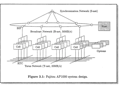
Figure 3.1 illustrates the Fujitsu AP1000 system design. The T-net is used for point-to-point communication between cells, the B-net for host to cell or cell to cell 1-to-N communication, and the S-net allows the host and cells to perform barrier synchronisation.
All cells and the host computer are connected by the B-net. The B-net is used for broadcasting data, data distribution and data collection. It acts as if it were a single common bus, but is implemented using compound networks which
§3.1 Fujitsu A P 1000 architecture 23
[image:34.537.60.478.84.383.2]Torus Network (T-net, 25MB/s)
Figure 3.1: Fujitsu AP1000 system design.
include hierarchical common buses and a ring structured network. Up to eight cells share the lowest level bus. Four buses are connected to the ring network, so that up to 32 cells form a hierarchical common bus which is connected with a ring node. The host computer is connected by a host interface, which also appears as one of the ring nodes. The B-net has a 32-bit data path and a data transfer rate of 50 Mbyte/sec. The B-net protocol is similar to that of a simple common bus. Before data transfer, a cell or host attempting to transfer data must flag a request to the B-net controller, then wait until the request is granted. After the B-net is granted to the requester, data transfer can commence.
The T-net implements a two dimensional torus topology. Each port of the T-net has a 16-bit data interface and each link has a data transfer rate of 25 Mbyte/sec. The message routing scheme implemented on the T-net is struc tured channel routing [61]. This routing incorporates the structured buffer pool algorithm into wormhole routing [33].
In wormhole routing the intermediate node stores only a few bytes of routing information, called a flow control digit or flit. When a routing node receives the message header, the node selects the channel of the next route. The node then transfers all subsequent blocks for that message header to the route selected. Although wormhole routing has the advantage of reduced latency, deadlock may occur and throughput may suffer because the message transfer blocks the channel.
50 Mbyte/s S-net
LBUS DRAM Controller
SPARC IU + FPU
DRAM 16 Mbyte
MSC Cache Memory
25 Mbyte/s 25 Mbyte/s ( R T C 25 Mbyte/s
25 Mbyte/s T-net
F ig u re 3.2: Fujitsu AP1000 cell architecture.
being transferred. Messages are routed in a fixed way, first in the x direction and then in the y direction. Provided there is no contention in the network, the latency is given by
160 x (D + N /4 + 1) nsec,
where D is the physical distance or hop count between the source and destination cell and N is the message size in bytes.
All cells and the host computer are also connected by the S-net, which is used for barrier synchronisation. The S-net has a tree topology and data is transferred serially. Data from each cell moves up to the root of the S-net along the tree branches. At intermediate nodes data is merged using a logical AND operator. Therefore, the logical AND of all the data is delivered to the root node. The result is then distributed to all cells along the tree from the root of the S-net. The S-net also allows cells to synchronise with the host.
3 .1 .2 C e ll a r c h ite c tu r e
Figure 3.2 illustrates the configuration of a Fujitsu AP1000 cell. Each cell has a 25 Mhz SPARC integer unit (IU), a 8.3 MFLOP floating point unit (FPU),
a message controller (MSC), a routing controller (RTC), a B-net interface (BIF),
§3.2 St ride message transfer 25
direct-mapped cache memory controller with a copy-back policy. The line size is four words.
The MSC, RTC, BIF and DRAM controller in each cell are connected via the LBUS (a 32-bit 40 Mbyte/sec synchronous bus). Each cell has an external LBUS connector. This enables the installation of hardware options such as a high-speed input/output interface, disc interface, vector processors and additional memory.
3.2
S trid e m essag e tr a n s f e r
The stride message transfer mode is a new message handling mode, developed for the Fujitsu AP1000, to support the collective communication routines presented in §3.3. This mode can operate in one of two ways. Either it transfers data items that are regularly located in a single message into a contiguous area of a cell’s local memory, or it stores the data items contained in a single message into regular locations of a cell’s local memory. This section describes in detail the operation of this mode and outlines its implementation.
3 .2 .1 A d d r e s s in g e le m e n ts o f a tw o - d im e n s io n a l a rr a y
A two-dimensional array is placed in memory so that elements take up a con tiguous block of memory. The array can be stored in either row-major ordering or column-major ordering. This thesis focusses on the Fortran programming lan guage. Because of the reliance on column-major ordering inherent in Fortran only column-major ordering is discussed.
If a two-dimensional array is stored using column-major ordering the columns of the array are placed in memory one after another. In general, for column-major ordering the elements are first sorted on the last index, then on the next-to-last index, and so on.
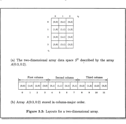
E x am p le 3.1 Figure 3.3(b) illustrates how the two-dimensional array M(0:3, 0:2) is stored in successive memory addresses in column-major order. ■ Consider the two-dimensional array A. Let A(0:ui,0:u2) declare the array. The two-dimensional array data space, denoted S 2, described by the array A is defined as
S 2 = {i e Z 2 I (0, 0) < (z'i, i2) < (ui, u2)},
where Uj is the upper bound of the jth (1 < j < 2) dimension of the array A. E x am p le 3.2 The array A(0:3,0:2) describes the two-dimensional array data space
S2 = {i g Z2 | (0,0) < (ii, ii) (3,2)}.
0 1 2
(0,0) (0,1) (0,2)
(1,0) (1,1) (1,2)
(2,0) (2,1) (2,2)
(3,0) (3,1) (3,2)
(a) The two-dimensional array data space S2 described by the array 4(0:3,0:2).
First column Second column
(0,0) (1,0) (2,0) (3,0) (0,1) (1,1) (2,1) (3,1) (0,2) (1,2) (2,2) (3,2)
0 1 2 3 4 5 6 7 8 9 1 0 1 1
Third column
(b) Array 4(0:3,0:2) stored in column-major order.
F ig u re 3.3: Layouts for a two-dimensional array.
The two-dimensional array is placed in memory as a contiguous block of data. This block of data, denoted S, is defined as
S — {2 (E Z I 0 < i ^ (ui + l ) ( u 2 Tl ) — l}.
E x a m p le 3.3 The array 4(0:3, 0:2) is placed in the contiguous block of data S = { i e Z \ 0 < i < 11}.
This block of data S is illustrated in Figure 3.3(b). ■ Each element of the array data space S2 maps to exactly one element in the block of data S. This mapping is represented by function C formulated as
£ : S 2 —> 5, £(i) = (1, U\ 4- 1) • (?i, *2)-
[image:37.537.61.474.71.475.2]§3.2 Stride message transfer 27
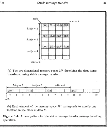
The stride message transfer mode allows individual data items of the array data space S2 to be transferred by a cell. The data items transferred by this mode are specified using the parameters hcnt, hskip, vent and vskip. These data items are described by a two-dimensional memory space. This two-dimensional memory space is defined as
M 2 = { j G Z 2 I (0,0) < (ji,j2) < {vent - l, hcnt - 1)}.
E xam ple 3.5 Consider the stride message transfer operation schematically in dicated in Figure 3.4(a). The shaded areas indicate the data items actually transferred by the operation. The two-dimensional memory space describing these data items is
M 2 = {j€ Z 2 (0,0) I < (ji’h)< (2,3)}. The labels on the shaded areas in Figure 3.4(a) illustrate this memory space. ■
Each element of the memory space M2 corresponds to exactly one location in the block of data S in which the array data space S 2 is stored. This mapping can be expressed as function A4 formulated as
A4 : M 2 —> S, A4{j) = addr + {hskip, hskip x {hcnt — 1) + vskip) • (A, j2), where addr is the first location in the block of data S to be transferred.
E xam ple 3.6 Function A4 for the stride message transfer operation illustrated in Figure 3.4 is
A4 : M 2 —>• S,A4{j) = addr + (3,10) • (A,
j2)-This function is illustrated in Figure 3.4(b). The data item (2,0) belonging to the memory space M 2 corresponds to memory location
A4(2, 0) — addr + (3,10) • (2, 0) = addr 4- 6,
as illustrated in Figure 3.4(b). ■
3 .2 .2 S tr id e m e s s a g e tr a n s fe r o p e r a t io n
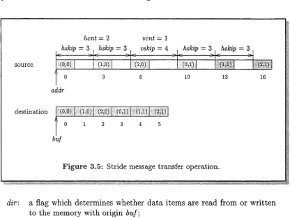
The stride message transfer operation is schematically indicated in Figure 3.5. The operation is applied to the contiguous block of memory with origin addr. The shaded items in Figure 3.5 indicate the individual data items written to the contiguous block of memory with origin buf. The relationship between these areas of memory is shown by the labels on the shaded areas in this figure.
addr
hskip = 3
hskip = 3
hcnt - 4
vskip = 4
\
1
(0,0) (0,1) (0,2) (0,3)
\
1
(1,0) (1,1) (1,2) (1,3)
\
1
(2,0) (2,1) (2,2) (2,3)
vent = 3
(a) The two-dimensional memory space M2 describing the data items
transferred using stride message transfer.
hskip = 3 hskip = 3 --- 3 * --- > tC
(0,0) (1,0)
vskip = 4
(2,0) (0,1)
2 3 4 5 6 7 8 9 10 11
addr
(b) Each element of the memory space M2 corresponds to exactly one
location in the block of data S.
F ig u r e 3.4: Access pattern for the stride message transfer message handling operation.
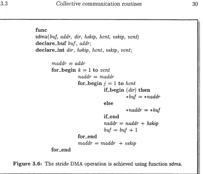
This pseudocode is representative of the high-level language used in a particular implementation. A description of the pseudocode is given in Appendix C.
Function sdma is applied to the contiguous block of data with address addr. The parameters to the function are:
[image:39.537.67.476.56.550.2]