Int. J. Electrochem. Sci., 14 (2019) 3740 – 3751, doi: 10.20964/2019.04.11
International Journal of
ELECTROCHEMICAL
SCIENCE
www.electrochemsci.org
Preparation and Properties of an Electroless Triple-Layered
Ni-P Based-TiO
2/ZrO
2Composite Coating
Qin-Ying Wang, Shuang Liu, Yi-Rong Tang, Rui Pei, Yu-Chen Xi*, Dai-Xiong, Zhang
School of Materials Science and Engineering, Southwest Petroleum University, Chengdu 610500, China
*E-mail: [email protected]
Received: 27 November 2018 / Accepted: 11 January 2019 / Published: 10 March 2019
We first reported here a new triple-layered Ni-P based-TiO2/ZrO2 (NTZ) composite coating prepared by electroless plating on a substrate of Q235 carbon steel. The microstructure, mechanical and anticorrosion properties of the achieved coating were investigated. Meanwhile, a pure Ni-P coating, a double-layered Ni-P based-TiO2 coating (NT) and a Ni-P based-ZrO2 coating (NZ) were prepared as comparisons. The results indicated that TiO2 and ZrO2 particles were found on the surface of NT and NZ. Both types of the particles were detected on the cross-section of NTZ. In addition, NTZ not only showed a higher tribology property than other coatings but also a similar hardness with NZ. Furthermore, the highest corrosion resistance of NTZ among all coatings was determined by the lowest corrosion current density of 3.80×10⁻⁷ A/cm2. Ni-P/TiO2 layer under Ni-P/ZrO2 layer in NTZ caused a higher corrosion resistance than NZ by increasing the corrosion path of harmful ions to substrate. The above research revealed that NTZ owned a potential application in the fields requiring both high mechanical and anticorrosion properties.
Keywords: Ni-P based-TiO2/ZrO2 composite coating; Electroless plating; Hardness; Tribology property; Corrosion resistance
1. INTRODUCTION
help improve the corrosion resistance of the Ni-P coating, and thus is extensively applied to refine its performance. The corrosion-improved efficiency mainly depends on the types of particles. In recent decades, Ni-P based-nano/micro particle composite coatings have been widely developed as the increasing need for the high quality and multifunctional coatings [1, 3]. For example, composite coatings Ni-P-SiC (SiC: 5 ~ 15 g/L, hardness: 510 ~ 580 HV0.05) [4], Ni-P-WC (WC: 3 ~ 12 g/L, hardness: 460 ~ 630 HV0.05) [5], P-ZrO2 (ZrO2: 0~90 g/L, hardness: 550 ~ 1100 HV0.1) [6], Ni-MWCNT (Ni-MWCNT: 0.1 ~ 0.4 g/L, hardness: 372 ~ 921 HV0.05) [7], etc. were developed to enhance the mechanical properties of the pure Ni-P coating [8]. Ni-P-TiO2 (TiO2: 1~10 g/L, corrosion current density (Icorr): 6.60 μA/cm2) [9], Ni-P-Mo (Mo: ~ 2 wt. %, Icorr: 13 μA/cm2) [10], Ni-Co-P-Al2O3 (Al2O3: ~ 4 wt. %, Icorr: 2.9×10⁻⁵ μA/cm2) [11], etc. were also prepared to improve the corrosion resistance of the pure Ni-P coating. Among the above particles, TiO2 and ZrO2 were widely employed in the electroless Ni-P coating to improve both mechanical and anticorrosion properties. Novakovic [12] found that the addition of TiO2 particles (200-300 nm) in Ni-P coating slightly increased corrosion resistance, while the hardness of the heated Ni-P-TiO2 composite coating was higher than that of the heated pure Ni-P coating. Meanwhile, smaller size TiO2 particles (25 nm) were reported to largely enhance the mechanical and anti-corrosion properties of the pure Ni-P coating. Both properties were further improved by increasing the content of TiO2 particles in plating solution [13]. The similar effect of ZrO2 (10-30 nm) particles was found by Song [14] and Wang [15]. In addition, the efficiency of nano TiO2 particles to increase the corrosion resistance of Ni-P coating seemed higher than that of ZrO2 particles, while that to enhance mechanical properties was opposite for the two particles by comparing the relevant literature [13, 14]. This phenomenon indicates that the mechanical and anti-corrosion properties can be improved to a satisfied value simultaneously by using both TiO2 and ZrO2 particles. Actually, Ni-P based composite coatings with the mixed two types of particles have been tried, e.g. Ni-P-PTFE-SiC [16], Ni-P- (mixed) RuO2/TiO2 [17] and Ni-P-Ag-Al2O3 [18]. However, most of them mainly focused on increasing mechanical properties or oxidation resistance. In addition, the inter-influence between the two types of particles cannot be avoided during plating, which will reduce the properties of composite coatings. Based on the above analysis, a study on electroless Ni-P based composite coatings with two separated layers was developed to improve both mechanical and anticorrosion properties, the high hardness of ZrO2 particle and the excellent anticorrosion property of TiO2 particle make them the suitable candidate for this purpose, which was rare reported.
In this study, we tried to improve the mechanical and anticorrosion properties of Ni-P coating by adding TiO2 and ZrO2 particles, and thus a Ni-P based-TiO2/ZrO2 triple-layered composite coating was developed. Then, the performance of the achieved coating was studied, which was also compared with those of pure Ni-P, double-layered Ni-P based-TiO2, and Ni-P based-ZrO2 coatings.
2. MATERIALS AND METHOD
2.1 Materials
[image:3.596.42.553.218.419.2]
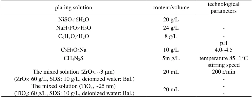
chemicals, NiSO4·6H2O was the source of nickel for Ni-P coating; NaH2PO2·H2O worked as reducing agent to promote the reactions of H2PO2- + H2O→HPO32- + H+ + 2H and H2PO2- + H→H2O + OH- + P to help form Ni-P coating; C2H3O2Na worked as complexing agent to control the rate of reaction; CH4N2S was a stabilizer to make plating solution stable; C6H8O7·H2O was used to adjust the pH of the plating solution; SDS (Sodium dodecyl sulfate) was a surfactant to prevent agglomeration of nano TiO2/ZrO2 particles.
Table 1. Compositions of the plating solution and technological parameters of electroless plating
plating solution content/volume technological
parameters
NiSO4·6H2O 20 g/L -
NaH2PO2·H2O 24 g/L -
C6H8O7·H2O 8 g/L -
C2H3O2Na 10 g/L
pH 4.0~4.5
CH4N2S 5m g/L temperature 85±1°C
The mixed solution (ZrO2, ~3 μm) 20 mL
stirring speed 200 r/min
(ZrO2: 60 g/L, SDS: 10 g/L, deionized water: Bal.) -
The mixed solution (TiO2, ~25 nm)
20 mL -
(TiO2: 60 g/L, SDS: 10 g/L, deionized water: Bal.) -
In this work, the Q235 steel (C 0.16, Mn 0.80, Si 0.37, P 0.04, S 0.04, Fe balance) was cut into approximate dimensions of 10 mm×10 mm×4 mm. Prior to the preparation, the surface of steel was grinded with waterproof abrasive papers (1500 grit), polished with corundum powders of 3~5 μm in diameter, and then ultrasonically cleaned in deionized water followed by ethanol and acetone. Next, the surface of the Q235 steel was etched by hydrochloric acid (15 wt. %) by referring the research of Luo [19]. Then, it was quickly rinsed with deionized water and put into plating solution (300 mL) successively. A pure Ni-P layer was achieved on the surface of the steel after 0.5 h, then the mixed solution (TiO2) was gradually added to the stirred plating solution to prepare the second layer of Ni-P/TiO2 for 0.5 h. Next, the achieved Ni-P-Ni-Ni-P/TiO2 composite coating was quickly moved to the stirred plating solution with the mixed solution containing ZrO2 particles to prepare the third layer of Ni-P/ZrO2. The preparing time was also 0.5 h. Finally, a triple-layered Ni-P based-TiO2/ZrO2 composite coating (NTZ) was obtained. Simultaneously, a pure Ni-P coating, a Ni-P based-TiO2 coating, and a Ni-P based-ZrO2 coating were prepared as comparisons. The preparing details of all the above coatings were summarized in Table 2. The constant temperature magnetic stirrer was used to prepare coatings.
Coatings Plating time
Ni-P NiP: 1 h
NT NiP: 0.5 h + TiO2: 1 h
NZ NiP: 0.5 h + ZrO2: 1 h
NTZ NiP: 0.5 h + TiO2: 0.5 h + ZrO2: 0.5 h
2.2. Method
A scanning electron microscope (SEM, EV0 MA15 ZEISS) equipped with an energy-dispersive X-ray spectrometer (EDS) was applied to observe the morphology and measure the elemental composition of coatings. An X-ray diffractometer (XRD, X Pert PRO MPD) was used to measure the phase compositions of coating at a scanning range of 0 ° to 60 °. A Vickers hardness tester (HXD-2000TM/LCD, Baoleng) was employed to test the hardness of coating surface under a load of 0.98 N and a dwell time of 15 s. A multifunctional scratching tester (MFT-4000) with a diamond indenter was used to measure the friction coefficients of coatings under a scratching speed of 5 mm/min and a gradually varied force of 0 ~ 10 N.
Electrochemical tests were carried out in 3.5 wt. % NaCl solution by an electrochemical workstation (CS310, Corrtest) at room temperature. The electrochemical impedance spectroscopy (EIS) was measured at a frequency range from 100 kHz to 10 MHz with an applied AC amplitude of 10 mV. The potentiodynamic polarization curve of the coating was tested at stable open circuit potential (OCP) achieved after the immersion time of 2 h with a potential scanning rate of 1 mV/s. A conventional three-electrode cell, containing a saturated calomel electrode (SCE) as the reference electrode, a platinum electrode as the counter electrode and the coating with an exposed surface area of 10 mm × 10 mm as the working electrode, was employed.
3. RESULTS AND DISCUSSION
3.1 Microstructure and composition
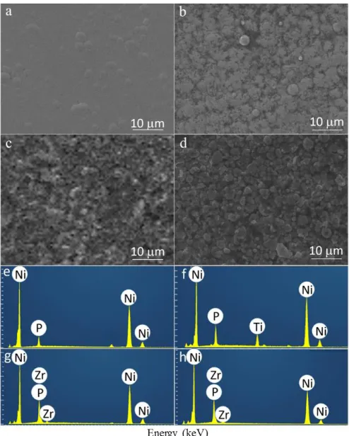
Figure 1. SEM micrographs and EDS map scanning results of coatings, a/e: pure Ni-P; b/f: Ni-P based-TiO2; c/g: Ni-P based-ZrO2; d/h: Ni-P based-TiO2/ZrO2
Table 3. Contents of elements on the pure Ni-P, Ni-P TiO2, Ni-P ZrO2 and Ni-P based-TiO2/ZrO2 coatings surface
Coating Ni-P NT NZ NTZ
O (wt. %) - 3.94 3.7 2.8
P (wt. %) 14.95 16.72 18.58 17.75
Ni (wt. %) 82.90 71.58 65.61 67.4
Zr (wt. %) - - 8.73 9.4
Calculated ZrO2 (wt. %) - - 11.8 12.7
Ti (wt. %) - 4.31 - -
Calculated TiO2 (wt. %) - 7.20 - -
[image:5.596.175.422.68.376.2] [image:5.596.45.551.476.634.2]
NTZ show the similar thicknesses around 3 μm. Meanwhile, Ni-P/TiO2/ZrO2 double layer in NTZ is composed of a Ni-P/TiO2 layer and a Ni-P/ZrO2 layer with the similar thickness of 1.5 μm. The white arrows and lines, as seen in Figure 2 b-d denote the different layers of the composite coatings. Additionally, the interfaces between all coatings and the corresponding substrates are clear and well-bonded, and the achieved coatings were uniform, compact, pore free, revealing satisfactory quality. These results are in accordance with those of Song [14].
Figure 2. Cross-sectional SEM morphology of coatings, a: pure Ni-P; b: Ni-P based-TiO2; c: Ni-P based-ZrO2; d: Ni-P based-TiO2/ZrO2
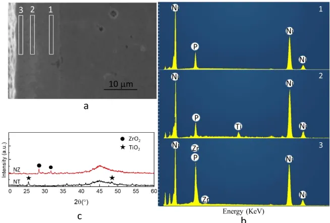
Figure 3. SEM image of cross-section of Ni-P based-TiO2/ZrO2 (a), and the EDS results within the regions 1, 2 and 3 at cross-section of Ni-P based-TiO2/ZrO2 (b), and the XRD patterns of Ni-P based-TiO2 and Ni-P based-ZrO2 (c)
[image:6.596.131.467.189.383.2] [image:6.596.148.475.442.663.2]
Zr and O are found on the top surface of NTZ, Ti and O are observed at region 2, while only Ni and P are found at region 1. The comparative results reveal that NTZ is composed of a P/ZrO2 layer, a Ni-P/TiO2 layer, and a Ni-P layer connecting each other from top surface to the steel substrate. In addition, the XRD patterns of NT and NZ were measured and provided in Figure 3 c. The characteristic peaks of TiO2 and ZrO2 are found by comparing the standard PDF cards in the XRD patterns of NT and NZ, respectively, indicating the successful deposition of the TiO2 or ZrO2 particles in each coating.
3.2 Mechanical property
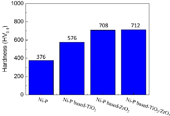
In order to learn about the effects of particles on the mechanical properties of electroless coatings, the hardness was tested and provided in Figure 4. The results reveal that the double-layered coatings exhibit the enhanced hardness as compared to that of pure Ni-P. This result is similar to the study of Makkar [21] and Gay [22]. In addition, the hardness of NZ is larger than that of NT. Efficient influence on enhancing hardness based on dispersion hardening by the additions of ZrO2 than TiO2 particles has been well illustrated [23, 24]. In addition, the Ni-P/ZrO2 layer with the thickness of 1.5 μm on NTZ surface displays the similar hardness above 712 HV0.1 with the Ni-P/ZrO2 layer of 3 μm on NZ. This phenomenon is attributed to the supportive effect of Ni-P/TiO2 layer under Ni-P/ZrO2 layer of NTZ. It means that the addition of TiO2 particles did not worsen the hardness of the triple-layered NTZ compared with NZ.
Figure 4. Vickers hardness of pure Ni-P, Ni-P TiO2, Ni-P ZrO2 and Ni-P based-TiO2/ZrO2 coatings
[image:7.596.147.446.416.620.2]
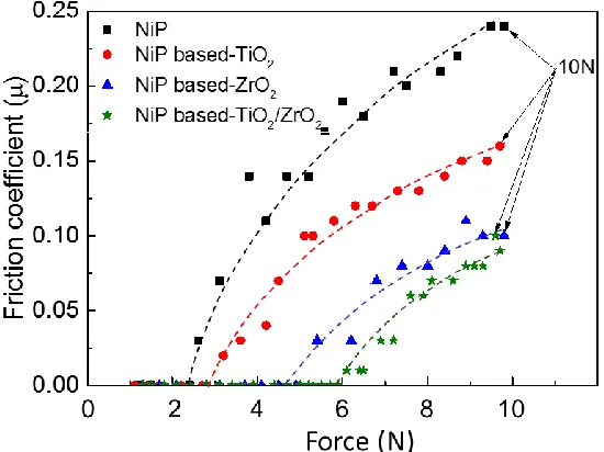
Furthermore, pure Ni-P and NT display friction coefficients of 0.24 and 0.16 at 10 N, respectively, which are larger than those of NZ and NTZ with the values around 0.1, which indicates that hard ZrO2 particles are beneficial to reduce the friction coefficient and improve the tribology property. Additionally, NTZ displays a slightly lower friction coefficient than NZ, revealing higher tribology property. This is mainly ascribed to the supportive effect of Ni-P/TiO2 layer under Ni-P/ZrO2 layer when NTZ was damaged by the indenter [26].
Figure 5. Friction coefficients of pure Ni-P, Ni-P TiO2, Ni-P ZrO2 and Ni-P based-TiO2/ZrO2 coatings
3.3 Corrosion behavior and mechanism
The EIS of coatings was done for determining whether NTZ owns the advantage in the field of corrosion prevention, as shown in the Figure 6. It is found that all coatings display one depressed capacitive loop within the whole frequency range. The radius of the capacitive loop from large to small is in the order of NTZ, NT, NZ and pure Ni-P, indicating decreasing corrosion resistance accordingly.
[image:8.596.161.436.191.397.2]
Figure 6. Nyquist plots of pure Ni-P, Ni-P based-TiO2, Ni-P based-ZrO2 and Ni-P based-TiO2/ZrO2 coatings in 3.5 wt. % NaCl solution.
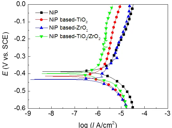
[image:9.596.132.438.77.289.2]Figure 7. Potentiodynamic polarization curves of pure Ni-P, Ni-P based-TiO2, Ni-P based-ZrO2 and Ni-P based-TiO2/ZrO2 coatings in 3.5 wt. % NaCl solution
Table 4. Corrosion potential (Ecorr) and corrosion current density (Icorr) of pure Ni-P, Ni-P based-TiO2, Ni-P based-ZrO2 and Ni-P based-TiO2/ZrO2
Coating Ni-P NT NZ NTZ
Ecorr (V) -0.381 -0.425 -0.431 -0.401
Icorr (A/cm2) 1.18×10⁻⁶ 4.78×10⁻⁷ 1.03×10⁻⁶ 3.8×10⁻⁷
[image:9.596.156.436.348.556.2]
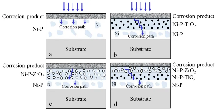
amorphous structure is usually difficult to be corroded for the absences of sensitive sites, i.e. grain boundaries, dislocations, and second-phase precipitates [29]. However, the possible uneven distribution of P on the surface of Ni-P coating during electroless plating will lead to micro-galvanic cells. As a result, the dynamic balance of Ni <—> Ni2+ + 2e- will be destroyed and the soluble NiCl2 formed through the reaction of Ni2+ + 2Cl− <—> NiCl2 will cause pitting corrosion [30], as shown in Figure 8 a. Fortunately, the above mechanism is changed by co-depositing particles of TiO2 and ZrO2 in coatings NT, NZ and NTZ. For one aspect, the presence of particles will prevent the gather of Ni or P, thus helps obtain a composite coating with a uniform matrix. This composite structure will lead to fewer galvanic cells to worsen corrosion. For another aspect, the oxide particles will act as barriers to block and prolong the corrosion path into the coating, which will further reduce corrosion, as schematically shown in Figure 8 b-d. Whereas, the difference in the types and concentrations of oxide particles will cause a slightly different corrosion mechanism for double-layered and triple-layered coatings. First, the volume fraction of ZrO2 in composite coatings is higher than that of TiO2, which is calculated by the ratio of the mass fraction (Table 3) and the density. The calculated volume fractions of ZrO2 and TiO2 particles in composite coatings are 1.43-1.7% and 0.93-1.16%, respectively. However, the particle size of TiO2 (25 nm) is much smaller than that of ZrO2 (3 μm), indicating a larger surface area. Therefore, the effect of TiO2 particles to block corrosion path is more efficient than that of ZrO2 particles. Meanwhile, smaller TiO2 particles will be in favor of forming a more compact structure. It is the reason why NT displays higher corrosion resistance than NZ, as presented in Figure 8 b-c. Furthermore, ZrO2 particles on the outer layer of NTZ mainly act as barriers to block harmful Cl- to penetrate into the under Ni-P/TiO2 layer, while the Ni-P/TiO2 layer show the similar corrosion resistance as that in NT. As a result, the combined effects of both Ni-P/ZrO2 and Ni-P/TiO2 layers for NTZ cause a higher corrosion resistance than NT, as shown in Figure 8 b, d. In addition, the nethermost P layer will display serious corrosion once the upper layers, i.e. P/ZrO2 or/and Ni-P/TiO2, are damaged.
[image:10.596.109.487.509.703.2]
Generally, the electroless plating method has got better mechanical and anticorrosion properties with uniform and well-connected layer system. Clearly, the current method to prepare the triple-layered coating is relatively complex, which requires electroless plating for at least two times, and thus this procedure needs to be further optimized. In addition, the study on the performance of the achieved coating in a real serving environment should be conducted before we can make confident statements on its practical application value.
4. CONCLUSIONS
A triple-layered NTZ composite coating was prepared by the method of electroless plating. The results showed the uniform morphology of NTZ containing ZrO2 particles in the top layer and TiO2 particles in the second layer. In addition, NTZ not only displayed the similar hardness as NZ but also showed a better tribology property than pure Ni-P and other coatings. Meanwhile, the highest corrosion resistance was found for NTZ with the lowest corrosion current density of 3.80×10⁻⁷ A/cm2. ZrO2 particles to block corrosion path in the top layer and TiO2 particles to cause a compact microstructure in the second layer of NTZ were believed the main reasons. The above research indicated that the achieved triple-layered Ni-P based-TiO2/ZrO2 coating exhibited the advantages in both mechanical and anticorrosion properties.
ACKNOWLEDGEMENT
This research was financially supported by Young Elite Scientists Sponsorship Program by China Association for Science and Technology (YESS, CAST) and Youth Scientific and Innovation Research Team for Advanced Surface Functional Materials, Southwest Petroleum University (No. 2018CXTD06).
References
1. J. Sudagar, J. Lian, W. Sha, J. Alloy. Compd., 571 (2013) 183.
2. J. Ru, Y. Jia, Y. Jiang, J. Feng, R. Zhou, Y. Hua, D. Wang, Surf. Eng., 10 (2016) 1. 3. M. Sarret, C. Muller, A. Amell, Surf. Coat. Tech., 201 (2006) 389.
4. J. Gao, L. Liu, Y. Wu, B. Shen, W. Hu, Surf. Coat. Tech., 200 (2006) 5836. 5. C. Zhao, Y. Yao, J. Mater. Eng. Perform., 23 (2014) 193.
6. P.A. Gay, J.M. Limat, P.A. Steinmann, J. Pagetti, Surf. Coat. Tech., 202 (2007) 1167.
7. A. Selvakumar, R. Perumalraj, P. Jeevananthan, S. Archana, J. Sudagar, Surf. Eng., 32 (2016) 338. 8. H. Liu, H.L. Yao, G.E. Thompson, Z. Liu, G. Harrison, Surf. Eng., 31 (2015) 412.
9. S.R. Allahkaram, S. Salmi, E. Tohidlou, Int. J. Mod. Phys.: Conference Series., 5 (2012) 833. 10. A.E. Fetohi, R.A. Hameed, K.M. El-Khatib, J. Power Sources., 240 (2013) 589.
11. J. Hu, L. Fang, X.L. Liao, L.T. Shi, Surf. Eng., 27 (2016) 1.
12. J. Novakovic, P. Vassiliou, K. Samara, T. Argyropoulos, Surf. Coat. Tech., 201 (2006) 895. 13. M. Momenzadeh, S. Sanjabi, Mater. Corros., 63 (2015) 614.
14. Y.W. Song, D.Y. Shan, R.S. Chen, E.H. Han, Surf. Eng., 23 (2007) 334.
15. Y. Wang, X. Shu, S. Wei, C. Liu, W. Gao, R.A. Shakoor, R. Kahraman, J. Alloy. Compd., 630 (2015) 189.
18. S. Alirezaei, S.M. Monirvaghefi, A. Saatchi, M. Ürgen, K. Kazmanli, Tribol. Int., 62 (2013) 110. 19. H. Luo, M. Leitch, Y. Behnamian, Y. Ma, H. Zeng, J.L. Luo, Surf. Coat. Tech., 277 (2015) 99. 20. J. Novakovic, M. Delagrammatikas, P. Vassiliou, C.T. Dervos, Defect. Diffus. Forum., 297-301
(2010) 899.
21. P. Makkar, R.C. Agarwala, V. Agarwala, Adv. Powder. Tech., 25 (2014) 1653.
22. P.A. Gay, J.M. Limat, P.A. Steinmann, J. Pagetti, Surf. Coat. Tech., 202 (2007) 1167. 23. Y. Yang, W. Chen, C. Zhou, H. Xu, W. Gao, Appl. Nanosci., 1 (2011) 19.
24. X. Wu, J. Mao, Z. Zhang, Y. Che, Surf. Coat. Tech., 270 (2015) 170. 25. S. Skolianos, T.Z. Kattamis, Mat. Sci. Eng. A-Struct., 163 (1993) 107. 26. Q.H. Wang, Q.J. Xue, H.W. Liu, W.C. Shen, J.F. Xu, Wear., 198 (1996) 216.
27. C.N. Cao, Principles of Electrochemistry of Corrosion, Chemical Industry Press, (2008) Beijing, China.
28. M.H. Ma, X.H Li, Y. Shan, Surf. Tech., 35 (2006) 45.
29. C.A. Souza, D.V. Ribeiro, C.S. Kiminami, J. Non-Cryst. Solids., 442 (2016) 56. 30. Y.W. Song, D.Y. Shan, E.H. Han, Electrochim. Acta., 53 (2007) 2009.