City, University of London Institutional Repository
Citation
:
Wijeratne, I., Kejalakshmy, N., Rahman, B. M. & Grattan, K. T. V. (2013).
Rigorous Full-Vectorial Beam Propagation Analysis of Second-Harmonic Generation in Zinc
Oxide Waveguides. IEEE Photonics Journal, 5(2), .6100112. doi:
10.1109/JPHOT.2013.2256115
This is the accepted version of the paper.
This version of the publication may differ from the final published
version.
Permanent repository link:
http://openaccess.city.ac.uk/14979/
Link to published version
:
http://dx.doi.org/10.1109/JPHOT.2013.2256115
Copyright and reuse:
City Research Online aims to make research
outputs of City, University of London available to a wider audience.
Copyright and Moral Rights remain with the author(s) and/or copyright
holders. URLs from City Research Online may be freely distributed and
linked to.
City Research Online:
http://openaccess.city.ac.uk/
[email protected]
1
Rigorous Full Vectorial Beam Propagation Analysis of Second
Harmonic Generation in Zinc Oxide Waveguides
I. N. M. Wijeratne, N. Kejalakshmy, Member, IEEE, B. M. A. Rahman, Senior Member, IEEE, and K. T. V. Grattan
School of Engineering and Mathematical Sciences, City University London, Northampton Square, EC1V 0HB, London, UK
Abstract: In this paper, a rigorous, full vectorial Finite Element (FE)-based Beam Propagation Method (BPM) has been implemented to study Second Harmonic Generation (SHG) in planar Zinc Oxide (ZnO) waveguides for the first time. It is shown here that the SHG output power is significantly improved when the waveguide structure is optimized. Furthermore, phase matching between the fundamental and the second harmonic modes, through the use of the quasi phase matching technique, is discussed.
Index Terms:Second Harmonic Generation (SHG), ZnO Waveguide, Finite Element Method (FEM), Beam Propagation Method (BPM).
1. Introduction
Lately, there have been considerable advancements in adapting nanotechnology for a variety of engineering applications. Among various nano-scale devices, nanowires are widely utilized in nanophotonics. In such optical devices, Second Harmonic Generation (SHG) continues to play a vital role in a wide range of applications such as cell imaging in biology [1]. In addition to the optical waveguide structures, materials with lack of inversion symmetry such as LiNbO3, KNbO3, BaTiO3 and ZnO have been used to fabricate optical waveguides due to their higher second order
nonlinear optical response (i.e. second-order nonlinear susceptibility 𝜒(2)).
There has been a continuous demand for materials with a high Non-Linear Optical (NLO) response. Among the various materials available, Lithium Niobate (LiNbO3) exhibits excellent properties of second order nonlinearity with the use of
periodical poling methods [2], which can be utilized in many second order NLO devices [3]. However, it is challenging to achieve high second order nonlinearity in nanoscale LiNbO3 waveguide structures due to lack of flexibility and the high
costs required for their practical implementations, such as is needed in modern crystal growth technology. Hence there is a growing demand for alternative NLO materials in which the waveguide cross-section can be reduced to enhance effective nonlinearity.
Furthermore, Zinc Oxide (ZnO), a II-VI semiconductor, has many excellent optical and photomechanical properties compared to those of other nonlinear materials such as LiNbO3 and has the capability to be deposited on different types
of substrates [4]. Alternatively, ZnO can also be grown on various substrates such as silica [5], silicon [6], GaAs [7], quartz [8], diamond [9], Diamond-Like-Carbon (DLC) [10, 11], LiTaO3 [12] and LiNbO3 [13]. Therefore, due to their
positive characteristics in terms of their fabrication potential and ability to be readily integrated, ZnO nanomaterials are promising candidates for integrated optics devices such as solar cells, lasers and transparent transistors and ZnO-based blue light emitting diodes (LEDs) etc. [14]. Furthermore, second order susceptibilies in ZnO can be enhanced by decreasing the thin film thickness, regardless of the technology being used. Further, by varying the growth time in ZnO nanorods, it is possible to vary the aspect ratio and the second order suceptibilities [15]. Moreover, exploiting SHG in various forms of ZnO is becoming popular for a wide range of applications, especially in biophonics where it is used to better understand some of the biological molecules used [16]. Studying induced luminescence is another aspect of the use of SHG in ZnO [17] and recently, ZnO has been employed as a hybrid optical material for fabricating integrated active optical devices operating in the visible, near-infrared, mid-infrared and THz frequency regions, taking full advantage of the highly transparent nature of ZnO [18].
1.1 Structure of the paper
This paper is organized as follows. Section 2 details the theoretical background of SHG generation, while Section 3 provides a description of the numerical methods used. Section 4 provides a description of the ZnO waveguide structure considered and Section 5 presents detailed results of the investigation carried out. Finally, Section 6 draws conclusions.
2. Theoretical Background
2
mathematically using a second order term proportional to the second order nonlinear susceptibility, 𝜒(2) (i.e. nonlinear susceptibility tensor 𝑑= 1 2 𝜒⁄ (2) ) and the square of the applied electric field (𝑬) as follows [24]:
𝑃𝑁𝐿= 2𝑑𝐸𝐸 (1)
In this nonlinear process, electromagnetic fields exchange energy between the fundamental and second harmonic frequencies where this represents the phenomenon of SHG. However, only materials with lack of inversion symmetry have a quadratic nonlinear susceptibility term and non-vanishing second harmonic susceptibility tensor term. In general, the induced polarization can be written as follows;
𝑃𝑁𝐿=� 𝑃𝑥 𝑃𝑦 𝑃𝑧
�=�𝑑𝑑1121 𝑑𝑑1222 𝑑𝑑1323 𝑑31 𝑑32 𝑑33
𝑑14 𝑑15 𝑑16 𝑑24 𝑑25 𝑑26 𝑑34 𝑑35 𝑑36 � ⎣ ⎢ ⎢ ⎢ ⎢ ⎢ ⎡ 𝑒𝑥2
𝑒𝑦2 𝑒𝑧2 2𝑒𝑦𝑒𝑧 2𝑒𝑧𝑒𝑥 2𝑒𝑥𝑒𝑦⎦
⎥ ⎥ ⎥ ⎥ ⎥ ⎤ (2)
where 𝑃𝑥, 𝑃𝑦 and 𝑃𝑧 are the components of nonlinear polarization, 𝑑𝑖𝑗(𝑖= 1. .3,𝑗= 1. .6) are the nonlinear susceptibility tensors and 𝑒𝑥, 𝑒𝑦 and 𝑒𝑧 are amplitudes of the 𝑥, 𝑦 and 𝑧 components of the electric fields respectively.
ZnO thin films exhibit significant second-order nonlinear susceptibility 𝜒(2) across different crystallinities and thicknesses [19]. Another advantage of using ZnO films is that the well-defined crystal polarity can be identified in advance in order to understand the origin of the NLO response in the thin film [20]. ZnO thin films have been employed in many practical applications e.g. nanocrystalline ZnO thin film for gas sensor applications [21] and in producing ZnO thin film transistors (TFTs) [22] for next-generation displays. ZnO waveguides can also be used to fabricate low power CMOS-compatible ZnO nanocomb-based gas sensors. In this paper, a ZnO nanostructure has been considered and it is assumed that the ZnO nanowires have been grown on a silica/silicon substrate with the crystal axis perpendicular to the silica/silicon substrate.
ZnO has a group symmetry of 6𝑚𝑚. The second order nonlinear susceptibilities of ZnO are, 𝑑33~ 18.0 𝑝𝑚/𝑉 and
𝑑15=𝑑31= 2.88 𝑝𝑚/𝑉 [15]. The nonvanishing components are 𝑑15, 𝑑24=𝑑15, 𝑑32=𝑑31 and 𝑑33 (i.e. by applying
Kleinman symmetry conditions). Equation (3) shows the nonlinear polarisation for 𝑥, 𝑦 and 𝑧 directions.
�𝑃𝑃𝑦𝑥 𝑃𝑧
�=�
2𝑑15𝐸𝑥𝐸𝑧 2𝑑15𝐸𝑦𝐸𝑧 𝑑15𝐸𝑥2+𝑑15𝐸𝑦2+𝑑33𝐸𝑧2
� (3)
3. Numerical Methods
Initially, a Full Vectorial Finite Element Method (FV-FEM) has been used for the modal analysis. The FV-FEM has been used to obtain the optimum ZnO planar waveguide structural parameters for SHG, following which the propagation constant (𝛽) and the generated modal fields are used in the Full Vectorial Finite Element Beam Propagation Method (FE-BPM) to analyze the evolution of the fundamental and second harmonic waves.
For modal analysis using the FV-FEM, the cross-section of a waveguide is discretized into a number of triangular elements using an irregular mesh. The FV-FEM, based on the vector 𝑯-field formulation, is used to obtain the modal field solutions and propagation constants of the fundamental and higher order Transverse Electric (TE) and quasi-Transverse Magnetic (TM) modes [25]. The full vector 𝑯-field formulation used in FV-FEM can be written as;
𝜔2=�∫�∇×𝐻��⃗� ∗∙1� �∇𝜀̂ ×𝐻��⃗�𝑑Ω�+�∫(𝜂 𝜀⁄ 0)�∇ ∙ 𝐻��⃗� ∗ �∇.𝐻��⃗�𝑑Ω�
∫ 𝐻��⃗ ∗∙ 𝜇̂�𝐻��⃗� 𝑑Ω (4)
where 𝐻��⃗ is the full-vectorial magnetic field, 𝜀̂ and 𝜇̂ are the permittivity and permeability, respectively, of the waveguide,
3
dimensionless parameter 𝜂 is used to impose the divergence-free condition of the magnetic field in a least squares sense to eliminate spurious solutions. Typically the penalty term, 𝜂= 1⁄𝑛𝑒2 is used, where 𝑛𝑒the effective index of the mode, and this is balances the electric and magnetic field energy via the waveguide impedances.
The propagation of radiation generated via SHG in an optical waveguide was analyzed by applying the Full Vectorial FE-BPM and numerically represented as follows;
For the fundamental frequency:
∇× [𝜀𝜔]−1∇×𝑯𝜔− 𝑘02𝑯𝜔 =𝑗𝜔𝜀0∇× [𝜀𝜔]−1[𝑑𝜔]𝑬2𝜔𝑬𝜔∗ (5)
For the Second Harmonic frequency:
∇× [𝜀2𝜔]−1∇×𝑯2𝜔−4𝑘02𝑯2𝜔=𝑗𝜔𝜀0∇× [𝜀2𝜔]−1[𝑑2𝜔]𝑬𝜔2 (6)
where an asterisk (‘*’) denotes a complex conjugate, k0 is the free-space wavenumber, 𝜀ω and 𝜀2ω are linear relative permittivity tensors at the fundamental and SH frequencies, respectively and 𝑑ω and 𝑑2ω are second order nonlinear susceptibility tensors at the fundamental and SH frequencies, respectively. Then it is necessary to consider the nonlinear part (i.e. R.H.S) of the equations (5) and (6) to find the nonlinear components in
𝑥
,𝑦
and𝑧
directions.By substituting 𝝍𝑵𝑳(𝑥,𝑦,𝑧) into the R.H.S. of equation
(6)
;𝝍𝑵𝑳(𝑥,𝑦,𝑧) =𝑗𝜔 �𝑖𝑥�𝜕𝑦𝜕 𝑃𝜀𝑧 𝑧−
𝜕 𝜕𝑧
𝑃𝑦 𝜀𝑦� − 𝑖𝑦�
𝜕 𝜕𝑥
𝑃𝑧 𝜀𝑧−
𝜕 𝜕𝑧
𝑃𝑥 𝜀𝑥�+𝑖𝑧�
𝜕 𝜕𝑥
𝑃𝑦 𝜀𝑦−
𝜕 𝜕𝑦
𝑃𝑥
𝜀𝑥�� (7)
Therefore, the
𝑥
component of the nonlinear part of the coupled wave equation can be written as;𝜓𝑁𝐿(𝑥) =𝑗𝜔 �𝑖𝑥�𝜕𝑦𝜕 𝑃𝜀𝑧 𝑧−
𝜕 𝜕𝑧
𝑃𝑦
𝜀𝑦�� (8)
By replacing𝜀𝑧=𝑛𝑧2,𝜀𝑦=𝑛𝑦2,
𝜔𝜀
0 =𝑘0⁄
𝑍0 and𝜕 𝜕𝑧⁄ =−2𝑗𝛽
the following equation can be obtained;
𝜓𝑁𝐿(𝑥) =𝜀𝑘0 0𝑍0�𝑖𝑥�𝑗
𝜕 𝜕𝑦
𝑃𝑧 𝑛𝑧2−2𝛽
𝑃𝑦
𝑛𝑦2�� (9)
where𝑍0denotes the free space impedance (≈377𝛺). The
𝑦
and𝑧
components can be calculated in a similar manner. Similarly, the R.H.S. of equation (5) (i.e.𝑗𝜔∇× [𝜀2𝜔]−1[𝑑2𝜔]𝑬2𝜔𝑬𝜔∗) can be expanded in order to find the nonlinear components of the fundamental frequency in the𝑥
,𝑦
and𝑧
directions.Then the application of FEM equations (5) and (6) will yield the following matrix equations (10) and (12) for the propagation model of the fundamental and second harmonic frequencies. The propagation model of the fundamental field can be represented in the form of equation (10): this equation can be obtained by assuming that the envelope of the field changes slowly in the
𝑧
-direction (propagation direction) (𝜕2⁄𝜕𝑧2≈0).−2𝑗𝑛0𝑘0�𝑴� �𝑑{𝑑𝑧𝝓𝜔}+ ([𝑲]− 𝑛02𝑘02[𝑴]){𝝓𝜔} = {𝝍𝑁𝐿𝜔 } (10)
where �𝑴� �can be written as;
�𝑴� �= [𝑴] + 1
4𝑛02𝑘02([𝑲]− 𝑛0 2𝑘
02[𝑴]) (11)
In equation (11), the [𝑴] and [𝑲] global matrices can be represent as;
[𝑴] =∑[𝑴]𝑒=∑ �
[𝑴𝑥𝑥]3×3 [0]3×3 [0]3×3 �𝑴𝑦𝑦�3×3� 𝑒
𝑒 and [𝑲] =∑[𝑲]𝑒=∑ �
[𝑲𝑥𝑥]3×3 �𝑲𝑥𝑦�3×3 �𝑲𝑦𝑥�3×3 �𝑲𝑦𝑦�3×3� 𝑒
𝑒
4
−4𝑗𝑛0𝑘0�𝑴� �𝑑{𝑑𝑧𝝓𝜔}+ ([𝑲]− 𝑛02𝑘02[𝑴]){𝝓𝜔} = {𝝍𝑁𝐿2𝜔} (12)Then the split-step procedure and Crank Nicolson (CN) scheme can be applied to both the fundamental and SH wave equations (i.e. equations (10) and (12) respectively) to derive the following;
[𝑨]𝑘{𝝓𝜔}𝑘+1= [𝑩]𝑘{𝝓𝜔}𝑘 (13)
where,
[𝑨]𝑘 =−2𝑗𝑛0𝑘0�𝑴� �𝑘+𝜃∆𝑧([𝑲]𝑘− 𝑛02𝑘02[𝑴]𝑘) (14)
[𝑩]𝑘 =−2𝑗𝑛0𝑘0�𝑴� �𝑘+ (𝜃 −1)∆𝑧([𝑲]𝑘− 𝑛02𝑘02[𝑴]𝑘) (15)
where∆𝑧is the propagation step size in the𝑧- direction, and the subscripts𝑘and𝑘+ 1denote the quantities related to the𝑘𝑡ℎ and
(𝑘+ 1)𝑡ℎ propagation steps respectively.𝜃 is an artificial parameter(0≤ 𝜃 ≤1). In this paper the CN scheme (θ= 0.5) has been adopted for numerical simulations of unconditionally stable systems and the propagation step size (∆𝑧) used as 0.1 𝜇𝑚 in the simulations.
Then the following equation can be derived for the fundamental frequency;
�𝝓𝜔(2)�𝑘+1=�𝝓(𝜔1)�𝑘+1+𝑗2𝛽𝜀∆𝑧 𝑟−1{𝝍𝑁𝐿
𝜔 } (16)
By applying equation (13) into equation (16) the following equation can be derived;
�𝝓𝜔(2)�𝑘+1=[[𝑩𝑨]]𝑘 𝑘�𝝓𝜔
(1)�
𝑘+1+𝑗 ∆𝑧
2𝛽𝜀𝑟−1{𝝍𝑁𝐿
𝜔 } (17)
In a similarly the following equation can be derived for the SH frequency;
�𝝓2𝜔(2)�𝑘+1=[[𝑩𝑨]]𝑘 𝑘�𝝓2𝜔
(1)�
𝑘+1+𝑗 ∆𝑧
4𝛽𝜀𝑟−1{𝝍𝑁𝐿
2𝜔} (18)
5
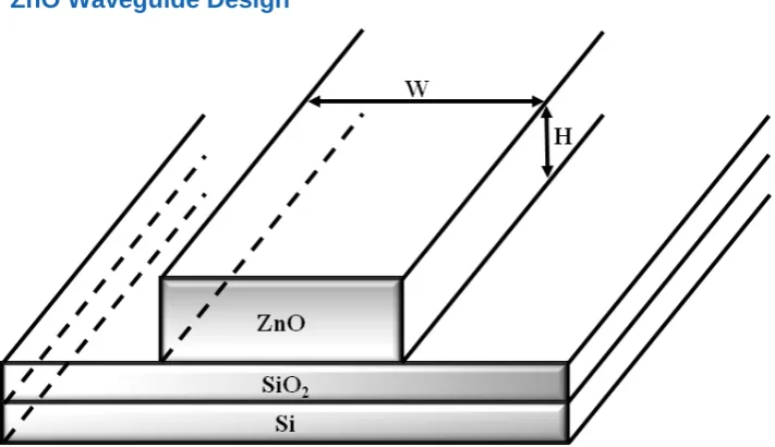
4. ZnO Waveguide Design
Fig.1 ZnO planar waveguide with silica buffer layer on a silicon substrate.
Fig. 1 shows the structure of the ZnO planar waveguide with a silica buffer layer on a silicon substrate. In Fig. 1, 𝐻and
𝑊 denote the height and the width of the planar waveguide, respectively. In practice, rectangular-shaped ZnO crystals have been used in the form of fabricated thin films, achieved by using different growing techniques, which have shown promising SHG performance. An initial investigation was carried out to optimize ZnO waveguides with different aspect ratios. The refractive indices of ZnO and SiO2 are taken as 1.95494 [26] and 1.54292 [27], respectively, at the
fundamental wavelength 𝜆𝜔 =1.064 𝜇𝑚. The refractive indices of the ZnO and SiO2 for the second harmonic wavelength 𝜆2𝜔=0.532 𝜇𝑚 were given by 2.04651[26] and 1.55609 [27], respectively. The ZnO waveguide with the SiO2 / Si
[image:6.595.48.404.77.282.2]6
5. Results
This section first discusses the stationary analysis of the ZnO waveguides including the effective index, spot-size and overlap integral. This is followed by an analysis of the modal propagation in the ZnO waveguides including the coherence length and QPM.
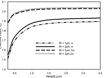
The variation of the effective index (𝑛𝑒𝑓𝑓) with height has been studied for the first order mode at two frequencies, 𝜔 and
[image:7.595.50.418.212.485.2]2𝜔, each with different widths, W (i.e. 1 𝜇𝑚 and 2 𝜇𝑚), and the results of this are shown in Fig. 2. Here, 𝑛𝑒𝑓𝑓=𝛽 𝑘⁄ 0 , where 𝛽 is the propagation constant and 𝑘0 is the wavenumber (𝑘0= 2𝜋 𝜆⁄ where 𝜆 denotes the wavelength). The first order mode 𝐻11𝑥 of the fundamental frequency, 𝜔, is indicated by 𝐻11𝑥,𝜔.
Fig. 2 Variation of the effective index of the propagating modes with the height at the fundamental and second harmonic frequencies for width values of 1 𝜇𝑚 and 2 𝜇𝑚.
As can be seen in Fig. 2, a reduction of the height results in a reduction of 𝑛𝑒𝑓𝑓 as the confined mode becomes exposed to the air cladding of the ZnO waveguide. Initially the effective indices of the modes reduce slowly, but these decrease rapidly as the modes approach their cut-off conditions (i.e. height values of 0.3 𝜇𝑚 – 0.7 𝜇𝑚). Moreover, the effective index of 𝐻11𝑥, 2𝜔 (i.e. 𝐻11𝑥 of the second harmonic frequency) is shown to move towards the cut-off condition at a lower rate than the𝐻11𝑥,𝜔 mode does. This is because the first order mode of the higher frequency (i.e. of second harmonic) is more confined in the centre of the ZnO core, in comparison with that of the lower frequency. Further, as the height is increased, the mode becomes more confined to the core, resulting in the value of 𝑛𝑒𝑓𝑓 asymptotically approaching the refractive index of ZnO (i.e. 𝑛𝜔 = 1.95494 and 𝑛2𝜔 = 2.04651). For very small dimensions the difference between the effective indices of the fundamental and SH wavelength is high indicating a deviation from the phase matching in the cut-off region.
7
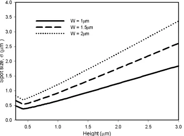
Fig 3 Variation of the spot-size of the 𝐻11𝑥mode of the fundamental frequency with the height for different width values.
The spot-size (𝜎) is an important modal parameter which can be used to better understand the power confinement and the resulting power density of the pump and the second harmonic modes. The spot-size, in this work, has been defined as the area where the Poynting vector is more than 1⁄𝑒2 of its maximum value for a given mode (or area where field is greater than 1⁄𝑒 of its maximum field value). Fig 3 shows the variation of the spot-size with height for the dominant first order modes 𝐻11𝑥) at the fundamental frequency, 𝜔, indicated by 𝐻11𝑥,𝜔 for different widths. For a given height, 𝜎 reduces when the width decreases from 2 𝜇𝑚 to 1 𝜇𝑚. For all the width values, it can be observed that 𝜎 reduces as the height is reduced until the cut-off condition is reached. However, when the dimensions of the waveguide reduces, 𝜎 also reduces due to the high confinement of the 𝐻11𝑥,𝜔, and as shown in Fig 3, a further reduction of the dimensions results in spreading the field into the air-cladding due to reaching the cut-off condition when the 𝐻 =0.4 𝜇𝑚. Therefore, the fundamental mode reaches its cut-off condition when 𝑊 =1 𝜇𝑚 more rapidly than when 𝑊 =2 𝜇𝑚. The relationship between 𝜎 and the dimensions of the ZnO waveguide is used as a guideline for design optimization.
It can be seen that lower height values give smaller spotsizes leading to a high SHG generation. However it should be
noted that when 𝐻< 0.5 𝜇𝑚 the second harmonic generation will deteriorate as the fundamental mode loses it high
8
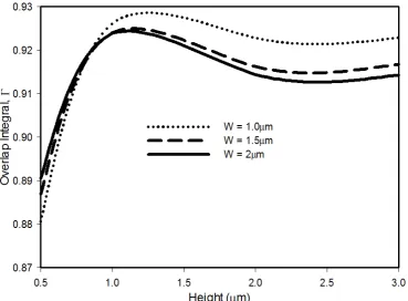
Fig. 4 Variation of the overlap integral of the 𝐻11𝑥 mode (between the fundamental and the second harmonic frequencies) against the height for different width values.
The overlap integral (𝛤) between the interacting fundamental and second harmonic first order dominant modes 𝐻11𝑥 relates directly to the efficiency of power transfer between these modes, i.e. a higher value of the overlap integral results in higher conversion efficiency and vice versa. The definition of the overlap integral is given below by [28]:
Γ
=
|
∬ 𝐸
𝜔2∙ 𝐸
2𝜔∙ 𝑑𝑥 ∙ 𝑑𝑦
|
�
(
∬ 𝐸
𝜔2∙ 𝑑𝑥 ∙ 𝑑𝑦
)
∙
(
∬ 𝐸
2𝜔2∙ 𝑑𝑥 ∙ 𝑑𝑦
)
(19)
where 𝐸𝜔 and 𝐸2𝜔 are the electric field distributions of the fundamental and second harmonic waves, respectively. Fig. 4 illustrates how the overlap integral of the first order modes 𝐻11𝑥 for the 𝜔 and 2𝜔 varies with the height over a range of width values. For small width values, both the 𝐻11𝑥,𝜔 and the 𝐻11𝑥, 2𝜔 modes are well confined and the overlap integral is high, particularly when height is also large. However, as has been mentioned, for a smaller waveguide width, its cut-off is reached more rapidly as the height is reduced; hence the overlap integral reduces in this operating range. It can be observed that, as the height decreases for a given value of width, the overlap integral initially increases, reaching a maximum value (in the region 1 𝜇𝑚≤ 𝐻≤ 1.3 𝜇𝑚) and then starts to decrease. This can be explained as follows: reducing the height makes 𝐻11𝑥,𝜔 and 𝐻11𝑥, 2𝜔 more confined which reduces the mismatch of their spot-sizes, leading to an increase in the overlap integral. However, as illustrated in Fig 3, when the height is very small the fundamental mode reaches its cut-off region more rapidly than the second harmonic mode, as shown in Fig. 2 and
Fig
3. Therefore, even though the second harmonic field becomes more confined to the core of the waveguide, the overall mismatch between fundamental and second harmonic fields becomes significant and the overlap integral starts to reduce at very small values of the waveguide heights.9
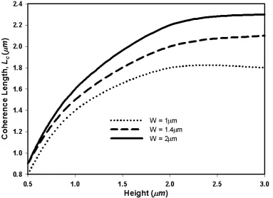
Fig. 5 Variation of the coherence length for the quasi-TM modes against the height with different width values.
The fundamental and second harmonic waves accumulate a 𝜋 radian phase shift over a distance known as the coherence length (𝐿𝑐). Here 𝐿𝑐 =𝜋 ∆𝛽⁄ and ∆𝛽=𝛽2𝜔−2𝛽𝜔, where 𝛽𝜔 and 𝛽2𝜔 are the propagation constants of the fundamental and second harmonic waves, respectively. The variation of 𝐿𝑐 with the height and width is shown in Fig. 5. Furthermore, a larger 𝐿𝑐 value would allow for a longer interaction between the fundamental and SH waves for higher SHG. As waveguide height decreases for a given width, the effective index, 𝑛𝑒𝑓𝑓 decreases due to the decreased area of the ZnO core enabling the confined mode to be more exposed to the air cladding. Therefore, the propagation constant (𝛽) decreases with 𝑛𝑒𝑓𝑓, as shown in Fig. 2. However, when the height increases, 𝛽𝜔 increases faster than 𝛽2𝜔 bringing
2𝛽𝜔 close to 𝛽2𝜔 (i.e. 2𝛽𝜔≈ 𝛽2𝜔) which results in a higher value of 𝐿𝑐. The ideal condition is possible if 𝑛𝜔 =𝑛2𝜔 (where
𝑛𝜔 and 𝑛2𝜔 are the fundamental and second harmonic refractive indices); however, this cannot be realized in practice
10
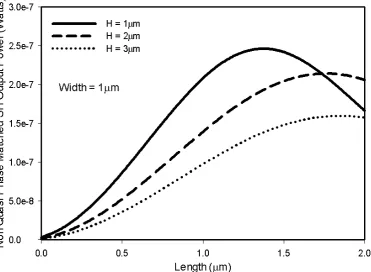
Fig. 6 Variation of the non-QPM SH output power with the propagation length for different height values.
11
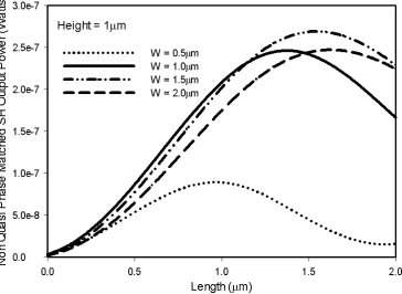
Fig. 7 Evolution of the non-QPM SH output power along the propagation length for different width values.
12
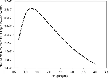
Fig. 8 Variation of the non-QPM maximum SH output power against the height.
As mentioned in Section 1, ZnO can be fabricated with different dimensions in order to achieve an optimized structure to produce maximum second harmonic output power. First, for each height value of the ZnO waveguide, the width value is optimized at which the non-quasi phase matched second harmonic output power is maximum (the range of width was between 1.3 𝜇𝑚 -1.6 𝜇𝑚): these maximum power values achieved after a propagation length equal to 𝐿𝑐 are shown in Fig. 8. As explained in Figs. 6 and 7, when the dimensions of the ZnO waveguide reduce, the SH output power generated increases due to the better mode confinement and improved overlap integral (unless the waveguide approaches mode cut-off). In Fig. 8, the maximum SH output power is obtained at a height of 1.3𝜇𝑚 with the corresponding width value of 1.5𝜇𝑚. It was observed that the dimensions of the maximum point as shown in Fig. 7 strongly support the 𝐻11𝑥 mode for both the fundamental and the second harmonic frequencies.
In the analysis above, it should be noted that the high SHG power achieved is limited by the respective coherence lengths. This limitation can be removed by a technique called quasi phase matching, where the sign of the nonlinear susceptibility ( χ(2)) of the core material is inverted periodically at every 𝐿𝑐 as explained in relation to Fig. 9
.
13
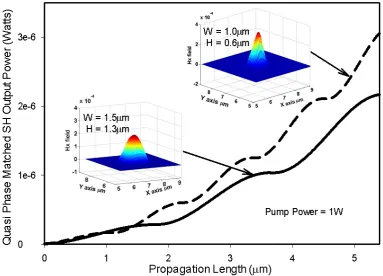
Fig. 9 Variation of the Quasi Phase Matched SH output power against the propagation length with different width and height combinations.
The direction of power exchange between the fundamental and second harmonic waves depends on their relative phase difference and this changes sign at a distance equal to the coherence length. Furthermore, noting the change of sign of the nonlinear susceptibility ( 𝜒(2)) at every 𝐿𝑐, by periodic poling, the phase of the polarization wave will be shifted by 𝜋, effectively re-phasing the interaction and leading to a monotonic power flow into the second harmonic wave [29]. In Fig. 9 the solid curve shows the first order Quasi Phase Matched (QPM) SH output power for a width of 1.5𝜇𝑚 and height of 1.3𝜇𝑚, i.e. optimized dimensions as per Fig. 6 and Fig. 7. In this case (i.e. solid curve) the 𝐿𝑐 is ~1.9𝜇𝑚. The fabrication of the QPM for every sub-micrometer scale 𝐿𝑐 (~1.9𝜇𝑚) can be achieved in practice by using different techniques such as the lithography technique [30]. Fig. 9 also shows the first order QPM SH output power for a core width of 1.0𝜇𝑚 and height of 0.6𝜇𝑚. In this case, the normalized conversion efficiency of 𝜂𝑛𝑜𝑟𝑚 = 1.0 x 10⁻⁷𝑊-1𝜇𝑚−2. This value was higher than the reported value of 𝜂𝑛𝑜𝑟𝑚 = 0.15 x 10⁻⁷𝑊-1𝜇𝑚−2 for a periodically poled LiNbO3 waveguide
device [31]. Although power conversion within a single 𝐿𝑐 section was lower for 𝐻 =0.6𝜇𝑚 and 𝑊 =1.0𝜇𝑚, compared to that for 𝐻 =1.3𝜇𝑚 and 𝑊 =1.5𝜇𝑚, its rate of energy transfer was higher. Therefore, when QPM was implemented, the overall SHG for the first case (i.e. 𝐻 =0.6𝜇𝑚 and 𝑊 =1.0𝜇𝑚) was higher as shown here. In Fig. 9, the inset mode profiles show the QPM SH output mode after propagation of a distance of 5.5𝜇𝑚.
6. Conclusions
In this paper, a rigorous full-vectorial FE based BPM formulation has been applied to find the mode spectrum of the different ZnO optical waveguide structures presented in an efficient and robust manner. This numerical method has been applied to analyze the modal solutions and the calculation of SHG in ZnO waveguides where inherently hybrid modes exist. It can be noted that by changing the height and width of the ZnO waveguide, it is possible to achieve improved SH output power. The higher output power is a result of the higher overlap integral due to the optimized modal properties in the waveguide structure. This paper shows that the SHG efficiency in ZnO can be higher than in the more widely used LiNbO3 based devices, due to the stronger confinement and the modal overlap integral. The QPM technique
[image:14.595.44.428.75.351.2]14
References
[1] D. Staedler, T. Magouroux, R. Hadji, C. Joulaud, J. Extermann, S. Schwungi, S. Passemard, C. Kasparian, G. Clarke, M. Gerrmann, R. Le Dantec, Y. Mugnier, D. Rytz, D. Ciepielewski, C. Galez, S. Gerber-Lemaire, L. Juillerat-Jeanneret, L. Bonacina, and J. P. Wolf, "Harmonic Nanocrystals for Biolabeling: A Survey of Optical Properties and Biocompatibility," American Chemical Society - Nano, vol. 6, pp. 2542-2549, Mar 2012.
[2] M. M. Fejer, "Nonlinear-Optical Frequency-Conversion," Physics Today, vol. 47, pp. 25-32, May 1994.
[3] F. A. Katsriku, B. M. A. Rahman, and K. T. V. Grattan, "Numerical modeling of second harmonic generation in optical waveguides using the finite element method," IEEE Journal of Quantum Electronics, vol. 33, pp. 1727-1733, Oct 1997.
[4] V. Kapustianyk, B. Turko, A. Kostruba, Z. Sofiani, B. Derkowska, S. Dabos-Seignon, B. Barwinski, Y. Eliyashevskyi, and B. Sahraoui, "Influence of size effect and sputtering conditions on the crystallinity and optical properties of ZnO thin films," Optics Communications, vol. 269, pp. 346-350, Jan 15 2007.
[5] N. Ylilammi, J. Ella, M. Partanen, and J. Kaitila, "Thin film bulk acoustic wave filter," IEEE Transactions on Ultrasonics Ferroelectrics and Frequency Control, vol. 49, pp. 535-539, Apr 2002.
[6] P. Wu, N. W. Emanetoglu, X. Tong, and Y. Lu, "Temperature compensation of SAW in ZnO/SiO2/Si structure," 2001 IEEE Ultrasonics Symposium Proceedings, Vol 1 and 2, pp. 211-214, 2001.
[7] V. Y. Zhang, J. E. Lefebvre, and T. Gryba, "SAW characteristics in a layered ZnO/GaAs structure for design of integrated SAW filters," 2001 IEEE Ultrasonics Symposium Proceedings, Vol 1 and 2, pp. 261-264, 2001. [8] K. K. Zadeh, A. Trinchi, W. Wlodarski, and A. Holland, "A novel Love-mode device based on a ZnO/ST-cut
quartz crystal structure for sensing applications," Sensors and Actuators A-Physical, vol. 100, pp. 135-143, Sep 1 2002.
[9] S. H. Seo, W. C. Shin, and J. S. Park, "A novel method of fabricating ZnO/diamond/Si multilayers for surface acoustic wave (SAW) device applications," Thin Solid Films, vol. 416, pp. 190-196, Sep 2 2002.
[10] M. H. Lee, S. M. Chang, C. K. Park, J. B. Lee, and J. S. Park, "Characterization of ZnO/DLC/Si saw devices using FCVA-produced DLC films," Proceedings of the 2002 IEEE International Frequency Control Symposium & PDA Exhibition, pp. 70-73, 2002.
[11] I. T. Tang, Y. C. Wang, W. C. Hwang, C. C. Hwang, N. C. Wu, M. P. Houng, and Y. H. Wang, "Investigation of piezoelectric ZnO film deposited on diamond like carbon coated onto Si substrate under different sputtering conditions," Journal of Crystal Growth, vol. 252, pp. 190-198, May 2003.
[12] F. Herrmann, M. Weihnacht, and S. Buttgenbach, "Properties of sensors based on shear-horizontal surface acoustic waves in LiTaO3/SiO2 and quartz/SiO2 structures," IEEE Transactions on Ultrasonics Ferroelectrics and Frequency Control, vol. 48, pp. 268-273, Jan 2001.
[13] K. Nakamura, H. Kitazume, and Y. Kawamura, "Optical TE-TM mode conversion using SH-SAW in ZnO/Y-X LiNbO3," 1999 IEEE Ultrasonics Symposium Proceedings, Vol 1 and 2, pp. 637-641, 1999.
[14] J. D. Ye, S. L. Gu, S. M. Zhu, S. M. Liu, Y. D. Zheng, R. Zhang, Y. Shi, Q. Chen, H. Q. Yu, and Y. D. Ye, "Raman study of lattice dynamic behaviors in phosphorus-doped ZnO films," Applied Physics Letters, vol. 88, Mar 6 2006.
[15] S. W. Chan, R. Barille, J. M. Nunzi, K. H. Tam, Y. H. Leung, W. K. Chan, and A. B. Djurisic, "Second harmonic generation in zinc oxide nanorods," Applied Physics B-Lasers and Optics, vol. 84, pp. 351-355, Jul 2006.
[16] B. E. Urban, P. B. Neogi, S. J. Butler, Y. Fujita, and A. Neogi, "Second harmonic imaging of plants tissues and cell implosion using two-photon process in ZnO nanoparticles," Journal of Biophotonics, vol. 5, pp. 283-291, Mar 2012.
[17] D. C. Dai, S. J. Xu, S. L. Shi, M. H. Xie, and C. M. Che, "Observation of both second-harmonic and multiphoton-absorption-induced luminescence in ZnO," IEEE Photonics Technology Letters, vol. 18, pp. 1533-1535, Jul-Aug 2006.
[18] S. Ono, H. Murakami, A. Quema, G. Diwa, N. Sarukura, R. Nagasaka, Y. Ichikawa, H. Ogino, E. Ohshima, A. Yoshikawa, and T. Fukuda, "Generation of terahertz radiation using zinc oxide as photoconductive material excited by ultraviolet pulses," Applied Physics Letters, vol. 87, Dec 26 2005.
[19] H. Cao, J. Y. Wu, H. C. Ong, J. Y. Dai, and R. P. H. Chang, "Second harmonic generation in laser ablated zinc oxide thin films," Applied Physics Letters, vol. 73, pp. 572-574, Aug 3 1998.
[20] J. S. Park, Y. Yamazaki, Y. Takahashi, S. K. Hong, J. H. Chang, T. Fujiwara, and T. Yao, "Origin of second-order nonlinear optical response of polarity-controlled ZnO films," Applied Physics Letters, vol. 94, Jun 8 2009. [21] F. A. Mahmoud and G. Kiriakidis, "Nanocrystalline ZnO thin film for gas sensor application," Journal of Ovonic
Research, vol. 5, pp. 15-20, Jan-Feb 2009.
[22] Y. Kawamura, N. Hattori, N. Miyatake, M. Horita, and Y. Uraoka, "ZnO Thin Films Fabricated by Plasma-Assisted Atomic Layer Deposition," Japanese Journal of Applied Physics, vol. 50, Apr 2011.
[23] A. Yariv, Quantum electronics, 3rd ed. ed. New York: Wiley, 1989.
[24] P. N. Butcher and D. Cotter, The elements of nonlinear optics: Cambridge University Press, 1990.
15
[26] M. Bass, E. W. Van Stryland, D. R. Williams, and W. L. Wolfe, Handbook of optics, 2nd ed. / Michael Bass, editor in chief / Eric W. Van Stryland, associate editor, David R. Williams, associate editor, William L. Wolfe, associate editor. ed. New York ; London: McGraw-Hill, 1995.
[27] M. Bass and V. N. Mahajan, Handbook of optics, 3rd ed. / Michael Bass, editor-in-chief. ed. New York: McGraw-Hill, 2010.
[28] C. Flueraru and C. P. Grover, "Overlap integral analysis for second-harmonic generation within inverted waveguide using mode dispersion phase match," IEEE Photonics Technology Letters, vol. 15, pp. 697-699, May 2003.
[29] D. S. Hum and M. M. Fejer, "Quasi-phasematching," Comptes Rendus Physique, vol. 8, pp. 180-198, Mar 2007. [30] A. P. Vasudev, J. A. Schuller, and M. L. Brongersma, "Nanophotonic light trapping with patterned transparent
conductive oxides," Optics Express, vol. 20, pp. A385-A394, 2012.