International Journal of Innovative Technology and Exploring Engineering (IJITEE) ISSN: 2278-3075, Volume-8 Issue-8, June, 2019
Abstract: Study deals with the development of a structurally safe, lightweight swingarm for a prototype performance geared electric motorcycle. Goal of the study is to improve the existing swingarm design and overcome its shortcomings. The primary aim is to improve the stiffness and strength of the swingarm, especially under extreme riding conditions. Cosalter’s approach was considered during the development phase. Secondary aim is to reduce the overall weight of the swingarm, without sacrificing much on the performance parameters.
Analysis was done on the existing design’s CAD model. After a series of iterative geometric modifications and subsequent analysis, two designs (SA2 and SA3) were kept under consideration. Materials used in SA2 and SA3 are AISI 4340 steel and Aluminium alloy 6061 T6 respectively. Both SA2 and SA3 were observed to be laterally and torsionally stiffer than SA1. The final models were observed to have an improved factor of safety than the existing model. Weight of SA2 was slightly more than SA1 (16% increase) whereas SA3 weighed considerably less (27.59% reduction) than the existing design SA1.
From the manufacturing point of view, SA2 is relatively easy and cheap to manufacture especially when the number of units are less compared to SA3, where it has to be either machined or casted.
Index Terms: Factor of safety, Stiffness, Swingarm, Weight reduction.
I. INTRODUCTION
Swingarm is one of the most indispensable parts in a motorcycle. It forms a crucial element in the working of a motorcycle since it is responsible for connecting the rear wheel assembly to the motorcycle frame. It is through the swingarm, driving force is transferred to the main frame from the rear wheels. Another major task of the swingarm is to provide provision for suspension. As a result, designing and optimizing swingarm is an absolute necessity while designing a new motorcycle.
Present day swingarms are of two types single sided and double sided. Double sided swingarm is the most commonly used, mainly due to its simplicity and symmetric design. Single sided swingarms are mostly reserved for track/racing motorcycles. Traditionally, swingarms consist of two trailing arms with suspensions mounted on either side towards the
Revised Manuscript Received on June 15, 2019
Swathikrishnan S, PG Scholar, Department of Mechanical Engineering, Amrita School of Engineering, Amrita Vishwa Vidyapeetham, Coimbatore, India
Pranav Singanapalli, CEO, eMotion Motors. 2/248, Cheran Residency, Prakasam Nagar, Othakalmandapam, Tamil Nadu 641032
A S Prakash, Assistant Professor, Department of Mechanical Engineering, Amrita School of Engineering, Amrita Vishwa Vidyapeetham, Coimbatore, India.
end. Since the adoption of mono suspension designs, cantilever type swingarm designs are preferred.
Swingarm stiffness plays a vital role in motorcycle handling and comfort. Designing a motorcycle that provides out of the world comfort at the same time handles exceptionally well is a humongous task. It is often a tradeoff between handling and comfort in most cases. As a result, swingarm stiffness should be meticulously chosen so as to provide the fine line between handling and comfort. Generally, a swingarm with a higher stiffness value handles well but suffers in ride comfort and vice versa.
Another important factor to be considered during design is the weight. Having a lightweight swingarm not only reduces the total weight of the bike, but more importantly reduces the un-sprung mass at the rear. This hugely improves the overall handling of the motorcycle.
II. LITERATURE REVIEW
Syed Hassaan Abdullah, Mohd Ahmed and Wajahath Abdul Rahman [1] utilized the shape optimization technique to further optimize a current MotoGP spec Honda RC213V swingarm. Optimization was done based on the multiaxial load analysis done on the swingarm CAD model. It has been observed that a 15% reduction in total weight has been achieved without compromising the factor of safety.
Ashish Powar, Hrishikesh Joshi, Sanket Khuley and D.P. Yesane [2] reverse engineered a 150cc commuter bike swingarm aimed at reducing its weight. They achieved the necessary weight reduction with geometry modification and material selection. Validation of the reverse engineered CAD model was done and compared with the original component. A total of 44% reduction in weight was achieved without compromising the stiffness.
Giacomo Risitano et al. [3] did studies on 3 World Superbike Championship spec swingarms to link objective data like stiffness and natural frequencies with subjective data such as handling and comfort. Objective data were obtained from specially designed test bench. These were compared with the subjective data perceived by professional riders. CAD and FE models were also created and analysed. CAD model and experimental model showed a variation of 8.42%. Test drivers noted that torsional stiffness provided better sensation to the rider while increased stiffness improved the feel of the bike.
João Diogo da Cal [4] as a part of Motostudent competition designed and developed frontal and rear swingarm for an electric motorcycle.
Design and Analysis of Swingarm for
Performance Electric Motorcycle
The study dealt with geometry as well as material selection for the swingarm. The swingarm has been modelled and simulated iteratively. Study showed that truss type design helped achieve a weight reduction of 66.1%. He also concluded that the tooling and manpower required to manufacture complex parts would undermine the cost efficiency of the project.
B. Smith and F. Kienhöfer [5] focused on the use of carbon fiber composites in motorcycle swingarm. Vertical and horizontal stiffnesses in carbon fiber swingarm were measured experimentally. FE modelling was carried out with assumptions, while the loading scenarios were kept the same as experimental. It was observed that vertical stiffness was sufficiently higher than that of the rear spring. Torsional stiffness was also comparable to the literature. The carbon fiber prototype model was found to have a weight reduction of 29% compared to its aluminium counterpart.
Aswath S et.al [6] concluded that Aluminium alloy 6061 T6 due to its good physical properties, high strength to weight ratios and weldability, is an ideal material for mars exploration rover chassis. The author chose aluminium 6061 T6 over other composites like carbon fiber due to its low cost. Paper also concludes that Aluminium alloy 6061 T6 will help improve the performance and strength and thereby making the mars rover chassis reliable.
Veeresh Kumar G B et.al [7] studied the effect of adding aluminium oxide (Al2O3) particles as reinforcement to improve the previously poor, wear resistance characteristics of aluminium alloy 6061 T6. Aluminium 6061 T6 with 6 wt% aluminium oxide composites exhibited excellent wear resistance when compared with other composites.
Chathakudath Sukumaran Sumesh and Ajith Ramesh [8] studied the influence of machine parameters on surface finish during dry orthogonal turning of aluminium 6061 T6. According to the studies, surface finish increases with increase in cutting speed. Feed rate was found to be the predominant factor that influences surface finish and lower feed rates improved surface finish.
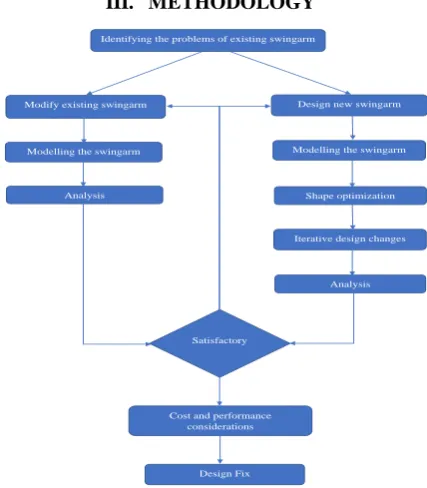
III. METHODOLOGY
Identifying the problems of existing swingarm
Modify existing swingarm Design new swingarm
Modelling the swingarm Modelling the swingarm
Analysis Shape optimization
Iterative design changes
Analysis
Satisfactory
Cost and performance considerations
Design Fix
Figure 1 Methodology
IV. MATERIALS
Trend in using metal alloys for critical structural parts and components for motorcycles has been there for a while. In recent times, there is a notable shift from previously used carbon steel alloys to aluminium alloys owing to their superior strength to weight ratio. Another important property of aluminium, to distribute loads throughout the component rather than having a localised deformation adds to the shift towards aluminium alloy as a sought after material for critical structural components, especially the swingarm. Reduction in weight of the swingarm helps reduce the total unsprung mass of the bike, which considerably improves the handling characteristics of the bike. Downside of using aluminium is the cost factor involved. Aluminium alloys are roughly four to six times costlier than its steel counterparts. Also manufacturing processes involved is slightly costly for aluminium alloys.
This project considers the option of two separate designs of swingarm, one with AISI 4340 Steel and the other with aluminium alloy 6061T6. Decision on which design to be finalised will be done after evaluating the cost and performance of the individual swingarms.
.
AISI 4340 Steel
[image:2.595.63.277.524.768.2]AISI 4340 is a medium carbon, low alloy steel widely known for its strength, toughness and good fatigue resistance. Nickel, chromium and molybdenum form the integral elements in its composition. 4340 steel has good impact and shock resistance as well as good wear and abrasion resistance. The material offers good ductility in annealed conditions. It can be an excellent choice of material for highly stressed parts.
Table 1 AISI 4340 Steel
Property Values
Elastic Modulus 205 GPa
Poisson’s Ratio 0.32
Mass Density 7850 kg/m3
Tensile Strength 1.11 GPa
Yield strength 710 MPa
Aluminium alloy 6061 T6
6061 T6 aluminium alloy is a precipitation hardened alloy with silicon and magnesium as major alloying elements. Unlike the 6061 T4, T6 is solution heat treated and artificially hardened. It is a medium to high strength alloy with good corrosion resistance and weldability. It is used in a wide range of industries from aerospace to automotive. Few of its mechanical properties are given in the table 2.
Table 2 Aluminium alloy 6061 T6
Property Values
Elastic Modulus 69 GPa
Poisson’s Ratio 0.33
Mass Density 2700 kg/m3
Tensile Strength 310 MPa
International Journal of Innovative Technology and Exploring Engineering (IJITEE) ISSN: 2278-3075, Volume-8 Issue-8, June, 2019
V. MOTORCYCLE SPECIFICATIONS
[image:3.595.46.291.133.327.2]Motorcycle under consideration is a prototype geared electric motorcycle. It has a fully electric drive train with a 4-speed manual gear box. Table 3 shows the complete specifications of the bike.
Table 3 Motorcycle Specifications
Motor 10 kW (peak) BLDC motor
Maximum Torque 28 Nm @ 2800rpm
Battery 40Ah, 72V Li ion
chemistry
Transmission 4-Speed Semi-automatic
Maximum Torque at wheels
517 Nm
Frame Steel Trellis Frame
Weight 140 kg
Wheel Base 140 mm
Weight distribution (Without rider)
50-50 Split
CG Height (Without Rider) 433 mm
VI. TEST PROCEDURE
Test procedures on the swingarm are based on Cossalter’s analogy of stiffness factors. According to Cossalter, the swingarm pivot should be locked while the loads are applied to the rear end of the swingarm, effectively making the swingarm act like a cantilever beam with fixed support. This however will not provide real world values since the fixed hinge will be structurally restricting, devoiding the function of suspension. The proposed solution is to have a hinged pivot, where the swingarm pivots with the trellis frame. The suspension support is a sliding fixture, provided at the same angle as that of the suspension.
A wheel spindle assembly is provided to restrict motions on the swingarm and provide close to actual simulation. Spindle assembly is made rigid (non-deformable) so that the loads are transferred directly to the swingarm and no load is used up for deformation of the spindle. Inclination of the swingarm is also considered during the application of loads.
[image:3.595.338.516.250.366.2]Figure 2 Swingarm pivot Figure 3 Suspension support
VII. LOAD APPLICATION A. Chain Pull
Chain pull is the force acting along swingarm when the maximum torque is supplied to the rear wheel via the chain. The motor, after all the gearing can supply 517 Nm of torque to the rear wheel. Chain being the link between the gearbox
front sprocket and the rear sprocket, has to experience a force of 4000N. Since the swingarm is at an angle to the longitudinal axis of the bike, the force is considered to be at the same angle from the axis of the swingarm to ensure close to actual simulation results.
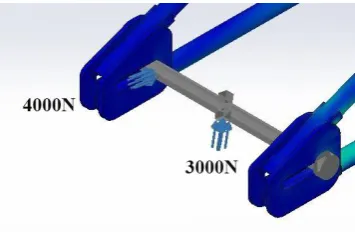
B. Extreme loading
Extreme loading is the extremist loading condition the bike is expected to go through. The scenario considered is the bike undergoing a front wheelie with two riders weighing 80 kg each. This results in a combined weight of around 300 kg, translating to a load of 3000N (2943N approximated) acting directly on the rear wheels. This load acts on the swingarm at an angle (angle of swingarm). Since front wheelie is characterized by sudden acceleration, maximum chain pull load also acts simultaneously on the swingarm.
Figure 3 Extreme Loading
C. Stiffness
Stiffness is the measure of how much resistance the swingarm will provide against different loading conditions. Stiffness is important since it decides how well the vehicle handles under multi load scenarios. A swingarm with high stiffness values transfer more road vibrations to the rider and hence make the ride less comfortable, however making the handling more predictable. A swingarm with less stiffness is more comfortable, however provides a poor feedback to the rider. As a result, rider feels the bike heavy and less predictable during cornering manoeuvres.
Lateral stiffness
Lateral stiffness is a measure of stiffness of the swingarm against load acting in the lateral direction. A load of 100 N is given to either of the sides of the swingarm and the resulting deflection is noted. Since the swingarm is symmetrical, stiffness on either of the sides will also be the same.
[image:3.595.48.272.571.668.2]Lateral stiffness =
Torsional Stiffness
[image:4.595.349.506.51.175.2]Torsional stiffness is the measure of stiffness of the swingarm against a torque acting along the longitudinal axis of the bike. A torque of 100 Nm is applied to the center of the wheel spindle and vertical deformation is noted down. From the vertical deformation, angle of deformation is calculated.
Figure 5 Torsional stiffness
Figure 6 Angular displacement measurement
Angular displacement, α = tan-1 Torsional stiffness, Ktorsional =
VIII. ANALYSIS A. SA1
[image:4.595.79.259.162.297.2]The swingarm design present on the prototype bike was incapable of handling the torque produced by the bike. CAD model of the existing swingarm is as shown. Material used in the CAD model is AISI 4340, weighing 3.59 kg.
Figure 7 SA1
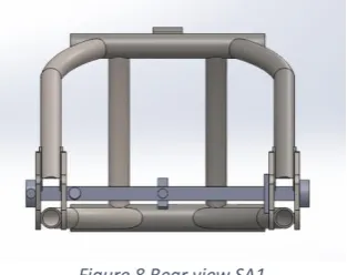
Figure 8 Rear view SA1
FE analysis on this swingarm showed the following results, which sets a benchmark for any further modifications.
[image:4.595.307.549.245.394.2]Chain Pull
Figure 9 SA1 Von mises stress concentration for chain pull
The model had a maximum local stress concentration of 463.7 MPa and showed a maximum total displacement of 0.811mm for the chain pull load of 4000N. Minimum factor of safety for this condition was 1.53
[image:4.595.309.544.493.639.2]Extreme loading
Figure 10 SA1 Von misses stress concentration for Extreme loading
The model showed maximum stress of 298.5 MPa at a different location which was quite lesser than the chain pull loading. This maybe because the two forces (loading and chain pull) forms a resultant, which acts differently on the swingarm. The model showed a maximum displacement of 1.127mm. Minimum FOS
[image:4.595.53.285.585.732.2]International Journal of Innovative Technology and Exploring Engineering (IJITEE) ISSN: 2278-3075, Volume-8 Issue-8, June, 2019
Stiffness Measurement
Lateral Stiffness
Load applied = 0.1kN
Lateral displacement of point A = 0.3503mm
Klateral = = 0.285 kN/mm
Torsional Stiffness
Torque applied = 0.1kNm
Vertical displacement of B = 0.3265mm
α = tan-1
(
) =
0.128oKtorsional = = 0.781 kNm/o
B. SA2
[image:5.595.309.550.53.476.2]SA2 design of swingarm is a modified version of SA1. Major modification includes the change in cross section of the lower arm from circular hollow to square hollow, keeping the thickness same. Few other modifications include reinforcements to make the swingarm stiffer and help distribute stresses evenly. The material used in the CAD model remains unchanged from SA1. However there is an increase in weight due to the modifications. Current weight of SA2 was 4.168 kg
Figure 11 SA2
Figure 12 Rear view SA2
Fig 13 Reinforcement 1 Fig 14 Reinforcement 2
Chain Pull
Figure 15 SA2 Von mises stress concentration for chain pull
The changed geometry helped reduce the stress concentration to 206.5MPa, which is a reduction of 2.24 times compared to the SA1 model. SA2 showed a maximum displacement of 0.35mm. Minimum FOS for chain pull condition was 3.43.
[image:5.595.305.558.146.346.2]Extreme Loading
Figure 16 SA1 Von mises stress concentration for extreme loading
[image:5.595.52.286.386.787.2] [image:5.595.304.558.459.616.2]Stiffness Measurement
Lateral Stiffness
Load applied = 0.1kN
Lateral displacement of point A = 0.1508mm
Klateral = = 0.663 kN/mm
Torsional Stiffness
Torque applied = 0.1kNm
Vertical displacement of B = 0.2229mm
α = tan-1( ) = 0.087o
Ktorsional = = 1.149 kNm/o
C. SA3
[image:6.595.313.541.73.556.2]SA3 started off as a completely new design, developed from scratch, with just basic dimensions in mind. Material preferred for SA3 is Aluminium alloy 6061 T6. The methodology was to first construct a solid aluminium swingarm and with the help of topology optimization tool, modify the geometry to reduce unwanted material. Multiple iterations of topology optimization and subsequent redesigning were done before arriving at the final model.
Figure 17 SA3 I
[image:6.595.77.279.358.493.2]SA3 I weighs 8.2 kg and forms the initial shape of swingarm with all dimensions included.
Figure 18 Topology study SA3
Fig 18 shows first iteration topology study. Topology study was carried out with best stiffness to weight ratio constraint. The study, points out regions on the swingarm which contributes less towards structural rigidity and helps user to have a better understanding on where to remove material for the purpose of mass reduction without actually compromising the stiffness of the swingarm. After a series of
studies and geometric modifications, a final design has been arrived upon which suits the requirements.
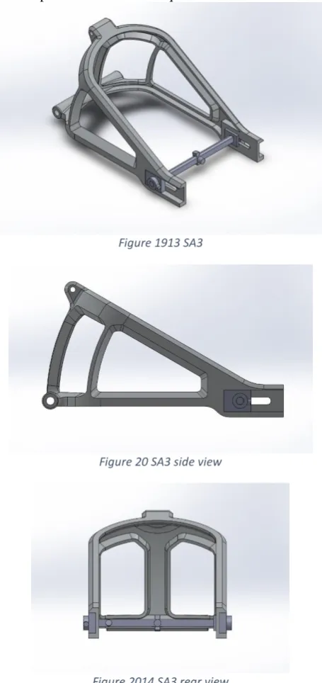
Figure 1913 SA3
Figure 20 SA3 side view
Figure 2014 SA3 rear view
SA3 swingarm weighed 2.6 kg as per the model whereas the initial SA3-I weighed 8.2 kg. From initial to the final model, a weight reduction of 68.29% was achieved. Though results from topology study were considered, they were not taken into account fully because the software suggested geometries will be difficult to manufacture in real world scenarios.
[image:6.595.56.283.539.687.2]
International Journal of Innovative Technology and Exploring Engineering (IJITEE) ISSN: 2278-3075, Volume-8 Issue-8, June, 2019
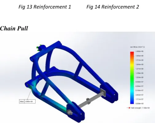
Figure 2115 SA1 Von mises stress concentration for chain pull
SA3 showed a maximum von mises stress of 117.5MPa and a maximum displacement of 0.82 mm for a chain pull loading of 4000N. The minimum FOS was found to be 2.34.
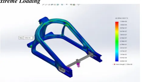
Extreme Loading
Figure 2216 SA1 Von mises stress concentration for extreme loading
SA3 showed a maximum von mises stress of 114.9MPa and a maximum displacement of 1.078mm during the extreme loading conditions. FOS was found to be 2.39.
Stiffness Measurement
Lateral Stiffness
Load applied = 0.1kN
Lateral displacement of point A = 0.4965mm
Klateral = = 0.201 kN/mm
Torsional Stiffness
Load applied = 0.1kNm
Vertical displacement of B = 0.2998mm
α = tan-1( ) = 0.118o
Ktorsional = = 0.847 kNm/o
IX. RESULT
Table 4 Results
FOS for SA2 in chain pull condition was greater than SA3 and SA1 by a considerable amount.
FOS for SA2 in extreme loading was slightly higher than SA3 and had a clear dominance over SA1. SA2 showed a clear supremacy over the other two
models in both lateral and torsional stiffness. SA1 and SA3 showed almost similar values wherein SA3 had a slight advantage over SA1.
SA3 had a clear-cut dominance over rest of the models in terms of weight. However, SA2 weighed slightly more than SA1.
SA2 was structurally superior than all the other models. SA2 was 2.32 times laterally and 1.47 times torsionally stiffer than the existing prototype swingarm SA1.
SA3 had a 27.59% weight reduction over the existing prototype swingarm SA1.
SA2 was 3.3 times laterally and 1.36 times torsionally stiffer than SA3 while SA3 was 33% lighter than SA2.
X. CONCLUSION
From the results obtained from the analysis, it is clear that SA2 is structurally stiffer and has slightly higher factor of safeties than SA3. As a result, SA2 should be theoretically more predictable and responsive in terms of handling but suffers from lower comfort levels since it is more likely to transfer road loads directly to the rider.
From the manufacturing point of view, for lower volumes, SA2 is preferable while for high volumes SA3 makes better sense. Material costs involved are comparatively lower for SA2 than SA3. SA3 has an advantage over reduced weight, which actually helps reduce the unsprung mass of the rear wheel, thereby increasing comfort as well as handling over uneven roads or technical conditions. Since it is comparatively less stiffer than SA2, it should help dissipate road loads thereby making the ride comfortable. However, the same aspect reduces the handling characteristics especially during corners and weave modes, making the bike feel heavier at the rear. Excessive flexibility can cause a phase lag, during which it becomes difficult for the rider to manoeuvre the bike. A fine line has to be drawn between comfort and performance and this can only be done with real world testing.
REFERENCES
1. Syed Hassaan Abdullah, Mohd Ahmed, Wajahath Abdul Rahman, Design of Racing Motorcycle Swingarm with Shape Optimisation, IJSRD - International Journal for Scientific Research & Development| Vol. 6, Issue 06, 2018
SA1 SA2 SA3
FOS
Chain pull 1.53 3.43 2.34
Extreme loading 2.37 2.78 2.39
Stiffness
Lateral (kN/mm) 0.285 0.663 0.201
Torsional (kNm/o)
0.781 1.149 0.847
[image:7.595.53.287.281.417.2]2. Ashish Powar, Hrishikesh Joshi, Sanket Khuley and D.P. Yesane, Design of Racing Motorcycle Swingarm with Shape Optimization, International Journal of Current Engineering and Technology (2016)
3. Giacomo Risitano, Lorenzo Scappaticci, Guglielmo Marconi, Carlo Grimaldi, Francesco Mariani, Analysis of the Structural Behavior of Racing Motorcycle Swingarms, SAE International: 2012-01-0207 (2012) 4. João Diogo da Cal Ramos, Front and Rear Swing Arm Design of an Electric Racing Motorcycle, Master of science degree thesis in mechanical engineering, Tecnico Lisboa. 2016
5. B. Smith and F. Kienhöfer, A Carbon Fibre Swingarm Design, R & D Journal of the South African Institution of Mechanical Engineering 2015, 31, 1-11
6. S. Aswath, Nitin Ajithkumar, Chinmaya Krishna Tilak, Nihil Saboo, Amal Suresh, Raviteja Kamalapuram, Anoop Mattathil, H. Anirudh, Arjun B. Krishnan, Ganesha Udupa, ‘An Intelligent Rover Design Integrated with Humanoid Robot for Alien Planet Exploration’, Robot Intelligence Technology and Applications 3 pp 441-457.
7. G.B.Veeresh Kumar, R.Pramod, C.S.P.Rao, P.S. Shivakumar Gouda, Artificial Neural Network Prediction On Wear Of Al6061 Alloy Metal Matrix Composites Reinforced With -Al2O3, Materials today : Proceedings Volume 5, Issue 5, Part 2, 2018, Pages 11268-11276 8. C.S. Sumesh and Dr. Ajith Ramesh, “Numerical modelling and
optimization of dry orthogonal turning of Al6061 T6 alloy”, Periodica Polytechnica Mechanical Engineering, vol. 62, pp. 196-202, 2018 9. Tony foale, Motorcycle handling and chassis design the art and science,