Abstract---The performance characteristics and fuel economy of a vehicle depends on chassis parameters such as its shape, dimension and design parameters, kerb weight, engine specifications etc. thereby having implications on its energy consumption. A comparative study to analyse the impact of chassis on different cars using IPG Carmaker software is conducted. In order to accomplish this, cars from four categories namely: Sports Utility Vehicle (SUV),Multi-Utility Vehicle (MUV), Hatchback and Sedan were selected in such a way that they have a similar engine displacement to ensure that the driving conditions are similar, the New European Driving cycle (NEDC) was taken as the testing standard. A Performance-Size-Fuel economy Index (PSFI) is used to quantify the extent to which technical efficiency gains have been achieved in an automobile. Upon simulation, obtained results show that the PSFI value for a car in the Sports Utility Vehicle category is nearly 29 percent lower than for a car in the Sedan category. This difference is mainly attributed to the chassis parameters which in turn influence the braking and acceleration performance as well as the fuel economy of the vehicle
Keywords: IPG Carmaker, NEDC, PSFI, Chassis parameters
I. INTRODUCTION
The energy crisis and environmental pollution are two of the most pressing global issues. This has a bigger problem on developing countries like India where consumption of petroleum products has a huge impact on its economic growth and fiscal deficit (Ramanathan, 1999). Fuel consumption by road transportation has increased four times between 1980 and 2000. This made a huge difference in the amount of emissions with it rising from 27MegaTonnes (Mt) in 1980 to 105 Mt in 2000 (Singh, Gangopadhyay, Nanda, Bhattacharya, Sharma& Bhan, 2008). Therefore, there is strong requirement to increase the fuel economy or reduce fuel consumption with the improved performance of automotive vehicle system. The kerb weight of the automobile and its physical dimensions hasa direct impact on fuel economy. Empirical equations denote that a 30 percent reduction in kerb weight increases vehicle mileage by around 15 percent (Mayyas, Qattawi, Omar& Shan, 2012).
Weight reduction is possible by using alternate materials like aluminium, high strength carbon or Carbon Fibre Reinforced Polymers (CRFP) (Mayyas et al., 2012). The dimension of an automobile has a direct impact on the aerodynamic drag force experienced by the car. A longer and compact automobile body is generally considered to be better for aerodynamic performance due to a lower frontal area thereby reducing the drag area which is the product of coefficient of drag (CD) and
frontal area (Fukuo, Fujimura, Saito, Tsunoda& Takiguchi, 2001).
These design based considerations therefore have the potential to increase the efficiency of an automobile. However, improved vehicle efficiency can be used to improve
the vehicle’s performance characteristics such as its acceleration performance orand improve its fuel economy. Hence, here the Performance-Size-Fuel economy Index (PSFI) which is the product of the vehicle’s power to weight ratio, the vehicle’s inside volume and fuel economy has been used to quantify the extent of trade-offs between the automobile’s performance, size and fuel economy (An &DeCicco, 2007). The difference in thePSFI values for each automobile can be directly attributed to factors like power loss due to road load which is the sum of power loss due to rolling resistance coefficient (RRC) and aerodynamic drag force (Gillespie, 1992) and inertia of automobile chassis. These factors influence the automobile’s acceleration and braking performance thereby impacting the performance and fuel economy of the automobile. In order to obtain these results, a car from each category namely Sports Utility Vehicle (SUV), Multi Utility Vehicle (MUV), Hatchback and Sedan were selected to have similar engine displacement of around 1200 cc. The New European Driving Cycle (NEDC) was implemented for simulating the driving cycle of all the selectedcars. TheNEDC has a road profile of straight roads, hence the load transfer during cornering and steering kickback diminution parameters are the limiting parameter of the simulation study (Rajeshkumar, Balasubramaniam, Bhavanakumar, Thirumalini, 2013).
Upon simulation, the following results were obtained:
1. Power loss due to road load, inertia of chassis. 2. Stopping distance of each car when decelerated from
120Kmph to rest by applying the same force on the brake pedal. This denotes the braking performance of each car.
3. Time taken for each car to travel 700 m when accelerated from rest by applying the same force on the gas pedal which indicates the acceleration performance of the car.
4. The absolute fuel consumption of each car.
These results show the impact of chassis parameters on the PSFIvalue, which in turn highlight the impact of these parameters on the automobile’s performance characteristics and fuel economy.
II. DRIVINGCYCLE
A driving cycle is the pattern of vehicle operation which is followed to conduct an emission and vehicle performance test (Barlow, Latham, McCrae &Boulter, 2009) and driving cycles are referred in terms of
vehicle speed and gear selection as a function of time (Barlow et al., 2009).
Study on Impact of Chassis on the Performance
of an Automobile with NEDC Simulation
2.1 The New European Driving Cycle (NEDC)
[image:2.595.307.557.57.200.2]The New European Driving Cycle (NEDC) is used for the approval of light duty vehicles. The cycle consists of periods of constant acceleration, deceleration and speed (Fontaras, Pistikopoulos& Samaras, 2008).The simulation is run on NEDC to ensure similar driving condition for each car during simulation. NEDC consists of two types of drive scenario. The first one is the Urban Driving Cycle (UDC) which represents the driving conditions of typical busy cities. A maximum speed of 50 kmph is allowed during this cycle with the average speed being 18.35 kmph (Fontaras et al., 2008). UDC is run four times with each having duration of 195 s, thereby having a run time of 780 s (Fontaras et al., 2008). UDC is followed by the Extra-Urban Driving Cycle (EUDC), which is designed to represent high speed driving modes. The maximum speed in the EUDC is 120 kmph with the average speed being 62.6Kmph (Fontaras et al., 2008) and a duration of 400 s.
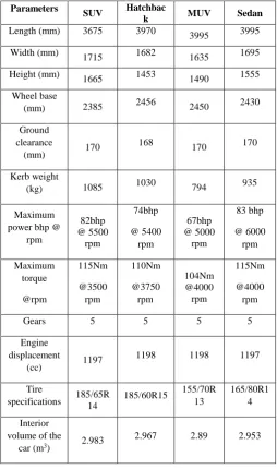
Table 1: Specification of the vehicles
On combining UDC and EUDC, the total duration of NEDC is 1180 s. The primary advantage of NEDC is that it has a steady test drive mode making it simple to drive and repeat the run.
Fig 1: The New European Driving Cycle (NEDC)
Since a comparative study to analyse the performance characteristics of the selected four cars require a common drive environment during the simulation of each of the four cars, the NEDC satisfies this objective. The NEDC is shown in Figure 1.
III. CARSPECIFICATIONS
The details of vehicles from the four categories namely: SUV, MUV, Hatchback and Sedan are given below in Table 1. These cars have the same range of engine displacement of around 1200 cc.
IV. PARAMETERSAFFECTEDBYAN
AUTOMOBILECHASSIS
The major parameters impacted by an automobile chassis are road load, chassis inertia kerb weight, braking performance and acceleration performance. These parameters are utilized in the discussion of the impact of chassis on the performance characteristics of automobiles.
4.1 Kerb Weight
Reducing the kerb weight of an automobile decreases the acceleration resistance of the automobile thereby having a direct impact in reducing the fuel consumption. Kerb weight also has a positive impact in reducing power loss due toRRC. Previous studies provide an empirical relation denoted by Eq. (1) which shows that a 30 percent reduction in kerb weightincreases mileage by nearly 15 percent (Cheah et al., 2009). The equivalent of Eq. (1) in kilometres per litre (kmpl) is given by Eq. (2).
Parameters SUV Hatchbac
k MUV Sedan
Length (mm) 3675 3970
3995 3995
Width (mm)
1715 1682 1635 1695
Height (mm)
1665 1453 1490 1555
Wheel base
(mm) 2385 2456 2450 2430
Ground clearance
(mm) 170
168
170 170
Kerb weight
(kg) 1085 1030 794 935
Maximum power bhp @
rpm
82bhp @ 5500
rpm
74bhp
@ 5400 rpm
67bhp @ 5000
rpm
83 bhp
@ 6000 rpm
Maximum torque
@rpm
115Nm
@3500 rpm
110Nm
@3750 rpm
104Nm @4000 rpm
115Nm
@4000 rpm
Gears 5 5 5 5
Engine displacement
(cc) 1197
1198 1198 1197
Tire
specifications 185/65R14 185/60R15
155/70R 13
165/80R1 4
Interior volume of the
car (m3) 2.983
[image:2.595.46.301.300.731.2](1)
(2)
4.2 Road Load
Road load denotes the summation of force due to RRC and aerodynamic drag force(Gillespie, 1992). Road load is impacted by the kerb weight of an automobile, RRC, air density, drag area and vehicle velocity. This is given by Eq.(3) (Gillespie, 1992). Equation 4 is a conceptual relation for fuel consumption and shows theoretically that reduction of road load has a direct impact on the reduction of fuel consumption (Haraguchi, 2011).
*CD*A (3)
(4)
4.2.1 Aerodynamic drag
The aerodynamic drag force is the air resistance an automobile experiences when it moves on the road. The main factor which impacts aerodynamic drag is the automobile’s drag area and velocity (Mohamed-Kassim& Filippone, 2010). This is given by Eq. (5).
(5)
The coefficient of aerodynamic drag (Cd) can be estimated by
Eq. (6)(Fenton, 1996):
CD (6)
Drag rating depends on the shape of different areas of an automobile’s body. This includes the plan and elevation of the automobile’s front, shape of the scuttle and wing cross-section, windscreen, roof top, boot, lower rear quarters and under body (Fenton, 1996). Areas which provide good air flow quality possess low drag rating while areas likely to spoil the flow quality have a greater drag rating (Fenton, 1996). The net drag rating is found by summing up the drag rating of each area of the car.
The coefficient of aerodynamic drag for wheels (CD, wheels) can
be estimated from Eq.(7) (Fenton, 1996):
(7)
The coefficient Cfe depends on the fender design and whether
the wheel has a hubcap or not. Current automobile designs have a fender which doesn’t cover the sides with the wheel having a hubcap. Therefore the Cfe value is taken as 0.0225
[image:3.595.318.532.119.237.2](Fenton, 1996). This is shown in Table 2.
Table 2: Values of coefficient Cfe
Fender type Cfe
Full Fender 0.0134
Fender doesn’t cover side, wheel
has flush hubcap 0.0225
Fender that doesn’t cover side 0.0267
No fender, wheel has flush hubcap 0.0924
No fender 0.11
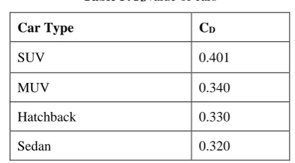
The CDvalues for the car from each of the four categories
arecalculated and are listed in Table 3.
Table 3:CDvalue of cars
Car Type CD
SUV 0.401
MUV 0.340
Hatchback 0.330
Sedan 0.320
4.2.2 Rolling resistance coefficient (RRC)
Tires represent one of the major power losses in an automobile. The power loss due toRRC is mainly due to the deformation of tire at the contact area between the tires and road surface (Redrouthu, 2014).Greater the deformation, greater will be the power required for the vehicle to overcome the loss. Power loss due to RRC mainly depends on kerb weight, RRC and vehicle velocity (Gillespie, 1992). This is denoted by Eq. (8).
(8) The RRC depends upon tire diameter, inflation pressure in tires, tire width and the aspect ratio (height to width ratio) of tires. The RRC for each of the selected car’s tires are calculated based on tire diameter, inflation pressure in tires, tire width and the aspect ratio of tires when run on dry asphalt road are shown in Table 4 (Redrouthu, 2014).
Table 4: Rolling resistance coefficient values Car Type Tire dimensions RRC
Hatchback 185/60R15 0.0217
SUV 185/65R14 0.0220
Sedan 165/80R14 0.0228
MUV 155/70R13 0.0230
Since the variation in RRCis comparatively low for each of the selected car’s tire, RRC’s impact on the difference in power loss due to RRC will be considerably lower when compared to the impact of kerb weight.
4.3 Braking Performance:
All the four selected cars have a four-channel four-wheel Anti-lock braking system (ABS). The ABS is an automated safety system which maintains the tractive contact of the automobile wheels with the road surface for any driving input thus preventing the wheels from locking up and hence avoids skidding (Gong, Yan& Liu, 2014). MATLAB Simulink ABS model was utilised. To realize optimum braking efficiency, the RRC needs to be maximum. The maximum RRC value is obtained when the slip ratio is
value and the best braking effect can be achieved (Gong et al., 2014).Therefore, slip ratio is taken as 0.2. The coefficient of friction versus Slip Ratio for dry asphalt road is as shown in Figure 2.
Fig2: Coefficient of friction vs. Slip Ratio
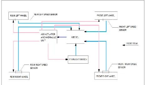
In the four-channel four-wheel ABS system, all the four wheels are connected to the ABS Electronic Control Unit (ECU) via speed sensors which are attached to each wheel. The ABS ECU controls the speed of each wheel in a way such that no wheel slips at a given time. This controlling is done through the hydraulic actuator unit. The schematic of ABS model is shown in Figure 3.
Fig 3:Four channel four wheels Anti-lock braking system
4.4 Acceleration Performance:
Acceleration performance is measured based on the minimum time taken by the vehicle to travel a fixed distance with the maximum acceleration possible. Large improvements in acceleration performance mean a smaller improvement in fuel economy (MacKenzie& Heywood, 2012). A major factor affecting a car’s acceleration performance is the car’s power to weight ratio, engine displacement and body type (Sedan, SUV, Hatchback or MUV) (MacKenzie& Heywood, 2012)
4.5 Inertia ofChassis:
Vehicle handling is affected by the moment of inertia and the location of centre of gravity of the vehicle. This includes the centre of gravity of engine and driveline components. As the moment of inertia and the centre of gravity can change significantly during operation, the impact of the shape of chassis in this regard needs to be considered (De Bruyne,
[image:4.595.309.545.152.283.2]Van der Auweraer, Diglio&Anthonis, 2011). Moment of inertia of vehicle is found using the vehicle’s length, width and height of a car (De Bruyne et al., 2011). Based on the dimensions of the car, the centre of gravity and moment of inertia was calculated by simulation code (Carmaker, 2014). This is listed in Table 5.
Table 5: Centre of gravity and moment of inertia for cars from each category:
Type Location of Centre of gravity (m)
Ixz
(kgm2)
MUV 2.229,0,0.566 5.966
Sedan 2.482,0,0.591 5.980
Hatchback 2.234,0,0.552 5.556
SUV 2.455,0,0.633 7.102
I. PERFORMANCE-SIZE-FUEL ECONOMY INDEX
Performance-Size-Fuel economy Index (PSFI) is the product of performance index (P) which is defined as the ratio of maximum engine horsepower to vehicle weight, the size index (S) which is the interior volume of the car and the fuel economy index (F) which is the fuel mileage (An &DeCicco, 2007).PSFI quantifies the trade-offs made between performance, size and fuel economy of the vehicle.
II. METHODOLOGY
The following steps were executed to simulate and make a comparative study on the impact of chassis parameters on the four selected cars.
1. First the NEDCwas created using Carmaker simulation code as a driving cycle for all the cars.
2. Four cars were selected from categories like SUV, MUV, Hatchback and Sedan based on the condition that they should have a similar engine displacement value. The car specifications are mentioned in Table 1, 2, 3 and 4.
3. Each car’s drag area was calculated based on the car’s frontal area, drag rating and the width and diameter of the car.
4. The four channel four wheel ABS was modelled in MATLAB Simulink software and incorporated into the carmaker software simulation code for all the cars. 5. Simulation was run and the required parameters were
recorded and studied for each car’s performance comparatively.
III. RESULTS AND DISCUSSION 7.1 Power Loss due to Road Load:
The power loss due to road load is the summation of the power loss due to RRCand the power loss due to aerodynamic drag.
7.1.1 Power loss due to aerodynamic drag:
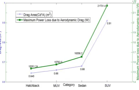
When the velocity of the four cars is constant, the power loss due to aerodynamic drag is found to be directly related to the drag area (Cd*A). This is denoted by Eq.(5). Aerodynamic
[image:4.595.59.291.414.551.2]1116 s to 1126 s during the NEDC. The variation of power loss due to aerodynamic drag for the corresponding change in drag area is shown in Figure 4.
Figure 4 shows that as the drag area increases, the maximum power loss due to aerodynamic drag increases. To highlight this point, in Figure 4, the car chosen from the SUV category has a higher drag area than the cars from all the other categories thereby having a higher power loss due to aerodynamic drag. Drag area depends on the frontal area of
the car.
Fig 4: Trend of power loss due to aerodynamic drag
7.1.2 Power loss due to RRC:
Equation 8 shows that when RRC rolling resistance coefficient and velocity is constant, the power loss due to RRC varies with the kerb weight of the car. At maximum velocity of 120 Kmph taken between 1116sec to 1126sec in the NEDC, power loss due to RRC alsobecomes more. Therefore, the maximum power losses due to RRC for each of
the four categories at 120kmph areshown in Figure 5. Fig 5: Trend of power loss due to RRC
From Figure 5, it is observed that as the kerb weight of each of the selected car increases, the power loss due to RRC also increases.To highlight this point, in Figure 5 the kerb weight of the SUV category is greater than the cars in the other categories thereby having a greater power loss due RRC. This signifies the impact of chassis parameter (kerb weight) on the performance of a given car.
Summing up the power loss due to both aerodynamic drag and RRC, the power loss due to road load for the car in each of the four categories are obtained. The average power loss due to road load is given in Table 6.
Table 6: Average power loss due to road load Category Average power loss due
to road load (W)
MUV 2965
Sedan 3260
Hatchback 3277
SUV 4044
Since power loss due to road load is a combination of both power loss due to aerodynamic drag and power loss due to RRC, the level of impact of both these parameters determine the power loss due to road load. The car for which both these factors are dominant will possess a greater average road load than that of the other cars.
7.2 Power Loss due to Inertia of Chassis:
Power loss due to inertia of chassis varies as a function of height of centre of gravity and the product of inertia of the vehicle (Allen, Klyde, Rosenthal & Smith, 2003). Lower the height of centre of gravity, lower will be the loading shift to the front wheels during braking and to the rear wheels during acceleration (Teoli, 1980). This leads to lower inertial resistance. Similarly, product of inertia is a direct measure of the imbalance in mass distribution around the centre of gravity. Therefore, lower the mass imbalance around the centre of gravity lower will be the product of inertia which in turn will lead to a lower power loss due to inertia of chassis.
Fig 6: Trend of power loss due to inertia of chassis
7.3 ABS Performance:
To measure the performance of the ABS, the four cars were decelerated from a speed of 120Kmph to rest in the NEDC from time 1126 s to 1180 s by applying the same force on the brake pedal. The stopping distance for each car was analysed. This is shown in Table 7.
Table 7: Stopping distance for the car from each category
[image:5.595.303.551.434.586.2] [image:5.595.41.281.476.632.2]Hatchback 544
SUV 516
Sedan 510
MUV 446
The stopping distance varies as the following parameters: • Kinetic energy.
• Mass distribution. • Presence of ABS • Road load of the vehicle.
The car having the lowest mass and hence the lowest kinetic energy is expected to have the lowest stopping distance. Kinetic energy depends on the kerb weight and velocity of the vehicle.Since the car selected from the MUV category has the least weight among the four categories; at a constant velocity this car has the least kinetic energy. However, the stopping distance of the car selected from the hatchback category is greater than that of the car from the SUV category although it has a lower kerb weight. This is related to the longitudinal slip of the car. The ABS is incorporated in an automobile to improve the stability and steer ability of the vehicle. The ABS poses a restriction that the longitudinal slip experienced by the tires shouldn't exceed 0.2.Therefore, the power absorbed by the brake system not only depends on the mass of the
vehicle but also on the longitudinal slip
(Delaigue&Eskandarian, 2004).Similarly, lower the mass imbalance around the centre of gravity lower will be the inertial resistance experienced by the car and hence the stopping distance increases (Allen et al., 2003).As the road load increases, the stopping distance of the car decreases. Since the road load of the car from the SUV category is higher than the cars from all the other categories, the car from the SUV category has a relatively shorter stopping distance when compared to the car from the other categories. These factors show the impact of chassis parameters on the performance characteristics of an automobile.
7.4 Acceleration Performance:
The acceleration performance of the cars in each of the four categories is measured in terms of the time taken to cover a distance of 700 m when accelerated from rest by applying the same force on the gas pedal for each car. The time taken is given in Table 8.
[image:6.595.308.543.49.95.2]The acceleration performance of an automobile varies as a function of the power loss due to road load and power to weight ratio. A low power loss due to road load combinedwith a high power to weight ratio implies that the acceleration performance of a car is higher. The car selected inroad loadwhen compared to the cars in the other categories. Although
Table 8: Time taken to travel 700 m
Category
Power loss due to road load (W)
Power to weight ratio (bhp/kg)
Time taken to travel 700 m(s)
Sedan 3260 0.08877 34.942
MUV 2965 0.08438 36.2986
Hatchback 3277 0.0718 36.8458
SUV 4044 0.0755 37.07
the car in theMUV has the lowest power loss due to road load among the four selected categories, its lower power to weight ratio when compared to the car in the sedan means its acceleration performance is lower than that of the sedan. Similarly, although the car in the hatchback has a lower power to weight ratio than the SUV, the higher road load of the car in the SUV means that its acceleration performance is lower than that of the hatchback.
7.5 Inference:
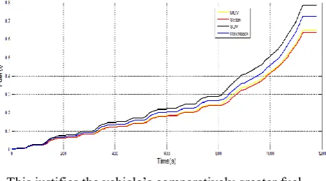
[image:6.595.65.275.51.128.2]Based on the various parameters discussed like power loss due road load, inertia of chassis, ABS performance and acceleration performance, the total fuel consumption of the selected cars from each category when it traversed the NEDCis given in Table 9. The fuel consumption for each of the car is shown in Figure 7.
Table 9: Total fuel consumption Category Total fuel consumption (l)
Sedan 0.6365
MUV 0.6484
Hatchback 0.7257
SUV 0.7859
Among the selected vehicles, the car from the SUV had the highest power loss due to road load and inertia of chassis.
This justifies the vehicle’s comparatively greater fuel consumption.
[image:6.595.320.533.291.399.2]Fig 7: Total fuel consumption for all categories This further highlights the impact of chassis parameters on the fuel consumption and performance of the automobile. The primary reason for the varying performance and thereby the fuel consumption among the selected cars is attributed to the trade-offs between the power to weight ratio, the interior volume of the car and the fuel economy. This is shown in Table 10.
[image:6.595.316.550.440.570.2]Author-1 Photo
Srinivaa s Ashok Kumar Category Performance
Index (W/kg)
Size Index (m3)
Fuel Economy Index (kmpl)
PSFI
(W/kg).m3kmpl
SUV 66.22 2.953 18 2505.809
Hatchback 62.95 2.89 18 2756.703
MUV 53.596 2.967 17.5 3274.659
Sedan 56.38 2.983 15 3519.858
Among the selected cars, the Sedan category has the best PSFI value. A higher PSFI value signifies better trade-off between performance, size and fuel economy of the car.
IV. CONCLUSION
The simulation of various car categories under the NEDC has provided effective results targeting the study of car chassis performance in fuel economy, power loss due to chassis inertia, power loss due to aerodynamic drag, braking performance and acceleration performance. Among the categories simulated the car selected from the SUV category has a higher size index, hence providing a better comfort factor. However, the SUV’s higher kerb weight and a higher drag area resulted in a higher power loss due to road load thereby resulting in a lower fuel economy. The car selected from the Hatchback category possesses the least power loss due to inertia of chassis due to the lower mass imbalance around the centre of gravity and least power loss due to aerodynamic drag due to the car’s lower drag area value. However, the hatchback’s higher kerb weight leads to a lower power-to-weight ratio, thereby providing only a marginally better fuel economy when compared to the SUV category. The cars from the Sedan and MUV category have the highest power to weight ratio among the four selected cars, thereby possessing better acceleration performance. This factor coupled with both the car’s lower kerb weight resulted in a comparatively higher fuel economy and a shorter stopping distance. However, both the cars have a relatively smaller size index thereby not providing the equivalent comfort factor when compared to the car from the Hatchback and SUV category. Therefore effort to ensure that the improvement in the design of a chassis will lead to a suitable trade-off between performances, size and fuel economy of the car needs to be undertaken. This work can also further be extended by running the simulations on various road surfaces and studying theeffect of tire parameters on the RRC, thereby understanding the impact on fuel consumption.
REFERENCES
1. Allen, R. W., Klyde, D. H., Rosenthal, T. J. & Smith, D. M. (2003). Estimation of passenger vehicle inertial properties and their effect on stability and handling. Journal of Passenger Cars-Mechanical Systems, 12, 112-132.
2. An, F. &DeCicco, J. (2007). Trends in technical efficiency trade-offs for the US light vehicle fleet, SAE Technical Paper, 1325-1341. 3. Barlow, T. J., Latham, S., McCrae, I. S. &Boulter, P. G. (2009). A
reference book of driving cycles for use in the measurement of road vehicle emissions. Parkin (Ed.). Transport Research Laboratory limited, 1-3
4. CarMaker, I. P. G. (2014). Reference manual version 5.0.2. IPGAutomotiveKarlsruhe Germany, 547
5. Cheah, L. W., Bandivadekar, A. P., Bodek, K. M., Kasseris, E. P. & Heywood, J. B. (2009). The trade-off between automobile acceleration performance, weight, and fuel consumption. SAE International Journal of Fuels and Lubricants, 1(1), 771-777.
6. De Bruyne, S., Van der Auweraer, H., Diglio, P. & Anthonis, J. (2011). Online estimation of vehicle inertial parameters for improving chassis control systems. In Proc. IFAC World Congr, 1814-1819.
7. Delaigue, P. &Eskandarian, A. (2004). A comprehensive vehicle braking model for predictions of stopping distances. Proceedings of the Institution of Mechanical Engineers, Part D: Journal of Automobile Engineering, 218(12), 1409-1417.
8. Fenton, J. (1996). Handbook of vehicle design analysis. England: Mechanical Engineering Publications Limited, 336-337
9. Fontaras, G., Pistikopoulos, P. & Samaras, Z. (2008). Experimental evaluation of hybrid vehicle fuel economy and pollutant emissions over real-world simulation driving cycles. Atmospheric environment, 42(18), 4023-4035.
10. Fukuo, K., Fujimura, A., Saito, M., Tsunoda, K. &Takiguchi, S. (2001). Development of the ultra-low-fuel-consumption hybrid car–INSIGHT. JSAE review, 22(1), 95-103.
11. Gillespie, T. D. (1992). Fundamentals of vehicle dynamics. SAE Technical Paper, 79-122.
12. Gong, T., Yan, H. & Liu, P. F. (2014). Modelling and Simulation for Anti-Lock Braking System (ABS) of Automobiles Based on Simulink. Applied Mechanics and Materials, 716, 1504-1507.
13. Haraguchi, Tetsunori, 2011. Reducing Fuel Consumption by Improved Vehicle Efficiency. ATZ worldwide Magazine, 113(4), 16-21 14. MacKenzie, D. & Heywood, J. (2012). Acceleration Performance
Trends and Evolving Relationship between Power, Weight, and Acceleration in US Light-Duty Vehicles: Linear Regression Analysis. Transportation Research Record: Journal of the Transportation Research Board, (2287), 122-131.
15. Mayyas, A., Qattawi, A., Omar, M., & Shan, D. (2012). Design for sustainability in automotive industry: A comprehensive review. Renewable and sustainable energy reviews, 16(4), 1845-1862. 16. Mohamed-Kassim, Z. & Filippone, A. (2010). Fuel savings on a heavy vehicle via aerodynamic drag reduction. Transportation Research Part D: Transport and Environment, 15(5), 275-284.
17. Rajeshkumar, S., Balasubramaniam, N., Bhavanakumar, R., Thirumalini, S., (2013). Steering Kickback Diminution on EHPS for Enhancing Vehicle Ride Comfort and Handling. SAE International, (2893).
18. Ramanathan, R. (1999). Short-and long-run elasticity’s of gasoline demand in India: An empirical analysis using co integration techniques. Energy economics, 21(4), 321-330.
19. Redrouthu, B. M. & Das, S (2014). Tyre modelling for rolling resistance, Master’s Thesis, Department of Applied Mechanics, Chalmers University of Technology, Sweden.
20. Singh, A., Gangopadhyay, S., Nanda, P. K., Bhattacharya, S., Sharma, C. &Bhan, C. (2008). Trends of greenhouse gas emissions from the road transport sector in India. Science of the total environment, 390(1), 124-131.
21. Teoli, A. (1980). U.S. Patent No. 4,236,459. Washington DC: U.S. Patent and Trademark Office.
22. Srinivaas Ashok Kumar et al., (2018). Simulation Study on Variants of ABS. International Journal of Engineering & Technology, 7 (3.6) (2018) 97-100.
AUTHORSPROFILE
G. Shivaguru Prakash, Department of Mechanical, EngineeringAmrita School of Engineering, Amrita, VishwaVidyapeethamAmrita University, Coimbatore, India.