Abstract: Sending power with good quality is the main objective of electrical transmission system. The load nature, in particular non-linear loads, makes the current at the point of common coupling (PCC) to include harmonics which further affects the other loads connected at PCC. Power quality improvement and management is an important study for the enhancement of electrical transmission and distribution systems to enrich the quality of power delivered at the utilization point. DSTATCOM is one among the FACTS controllers to improve the power quality by nullifying the effect of harmonics at PCC. This paper presents the analysis of dual DSTATCOM topology. In this each DSTATCOM is burdened such that the total compensating currents is shared between the two. Dual STATCOM topology is tested and the result analysis is shown with varying non-linear type loading conditions. Dual DSTATCOM is controlled using Instantaneous Reactive Power theory control logic. Parallel DSTATCOM has the advantage of reduction of switch rating and switching losses. The simulation work is carried out using Matlab/Simulink software.
Index Terms: Reactive power, Harmonics, parallel DSTATCOM, non-linear loads.
I. INTRODUCTION
Power system existence and reliability depends on the quality of power that is delivered at the point of utilization. The presence and increasing usage of non-linear loads makes the supply system more complex as they are the source of harmonics into the system. Using power electronic converters fine and smooth control is possible. But the major drawback of power electronic devices is that the system becomes nonlinear which is not desirable inducing non-linearity in the system and waveforms [1-3]. Apart from the existing nonlinear loads, these power electronic controllers make the system with reduced power quality. The major objective of the power system line is to supply the consumers with better quality in power. There are lot of parameters which influence the quality of power such as reactive power, harmonics [4-6], power factor, voltage sag and swell. The best solution to minimize the power quality issue is to use custom power devices which are also called as FACTS (flexible AC transmission system) controllers.
Different FACTS devices are STATCOM, APF,
DSTATCOM, DVR, and UPQC. STATCOM is used to compensate the reactive power and APF is used to compensate the harmonics. The D-STATCOM [7-9] is used to solve the issues like reactive power and harmonics. DVR compensates the voltage fluctuations and UPQC
Revised Manuscript Received on July 22, 2019.
P. V. V. Satyanarayana, Research Scholar, Department of EEE, Acharya Nagarjuna University, Guntur, AP, India
P. V. Ramana Rao, Professor & HOD, Department of EEE, Acharya
compensates all of the above said issues. But, depending on the issue these devices are connected in the system.
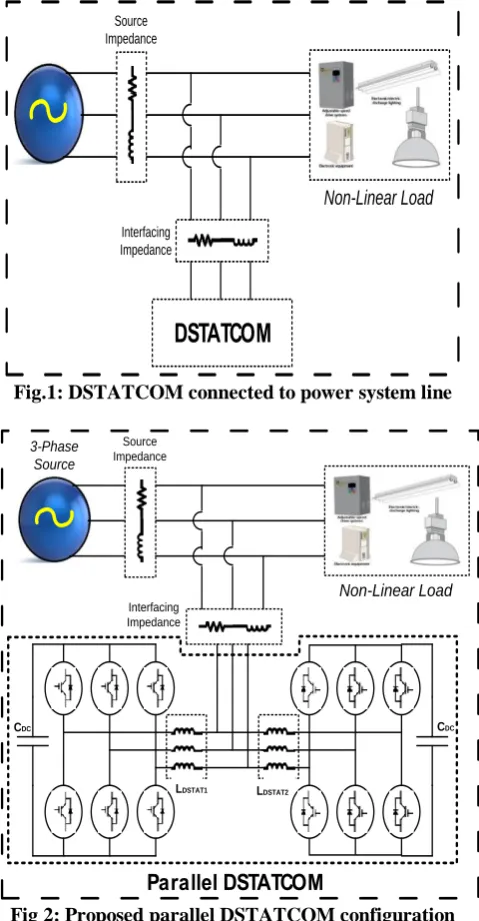
In this paper parallel DSTATCOM concept is implemented in which two DSTATCOM’s are connected in parallel to the power system line. The required reactive power and harmonic currents can be injected by controlling the DSTATCOM with suitable control logic. The control theory used in this paper is instantaneous reactive power [10]. The switches in the DSTATCOM are operated by giving gate pulses from control circuit. The advantage of using parallel DSTATCOM is that the number of switches can be reduced with less switching losses. The DSTATCOM connected to power system line is shown in figure 1. As the load is nonlinear, it draws nonlinear current introducing harmonics. DSTATCOM supplies compensating currents by injecting harmonic component of current to mitigate the harmonics.
This paper presents the analysis of dual DSTATCOM topology. In this, each DSTATCOM is burdened such that the total compensating currents is shared among the two. Dual STATCOM topology is tested and the result analysis is shown with varying non-linear type loading conditions. Dual DSTATCOM is controlled using instantaneous reactive power theory control logic. Parallel DSTATCOM gives the advantage of reduction of switch rating and switching losses. The simulation work is carried out by using Matlab/Simulink software.
II. SYSTEMWITHPARALLELCONNECTED
DSTATCOMCONFIGURATION
Figure 2 shows the parallel DSTATCOM configuration which is proposed in this paper. The system has nonlinear loads which draws nonlinear currents and deteriorates the power system. If only one DSTATCOM is connected, then point of common coupling is the only point where we need to send the compensating currents. These total harmonic currents must be injected by the same DSTATCOM, which increases the device ratings in DSTATCOM. To reduce the switch rating and switching losses two DSTATCOM’s are connected in parallel using an interfacing inductor. In this case, the parallel DSTATCOM configuration is able to mitigate the harmonics even when the nonlinear load is varying. In this work the load variation is made with incremental and decrement loads. Figure 3 shows the incremental load variation of parallel connected DSTATCOM configuration. This configuration acts as a harmonic compensator for power system. The DSTATCOM is a current injected device, so it is connected in parallel to line.
Parallel Connected Multi-DSTATCOM for
Power Quality Improvement in Distribution
System
DSTATCOM
Non-Linear Load
[image:2.595.52.292.52.513.2]Interfacing Impedance Source Impedance
Fig.1: DSTATCOM connected to power system line
Parallel DSTATCOM
Non-Linear Load
Interfacing Impedance Source Impedance 3-Phase
Source
LDSTAT1 LDSTAT2
CDC CDC
Fig 2: Proposed parallel DSTATCOM configuration
[image:2.595.385.548.297.381.2]III. CONTROLSTRATEGY
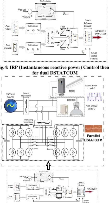
Figure 4 shows the control circuit for parallel DSTATCOM. The gating pulses are generated by the control circuit which is given to switches of parallel DSTATCOM. Current harmonics are suppressed using instantaneous reactive power theory. Instantaneous reactive power theory is based on set of time domain instantaneous powers. Instantaneous reactive power theory involves algebraic transformations called Clarke’s transformation of three-phase balanced voltage/current quantities to balanced two-phase quadrature quantities. The balanced three-phase voltage and current signals transformed (using Clarke’s transformation) to stationary quadrature signals are as (1) and (2).
(1)
(2)
The three-phase instantaneous active power component can be illustrated as in (3)
(3)
If the power components are to be separated with respect to their average and oscillating components:
Zero-sequence power, (4) Real power, (5) Reactive power, (6) The loss component of the power is estimated by comparing the actual and reference DC-Link voltages. The power loss component along with the estimated power components signals (4), (5) and (6) are processed to obtain reference source current signals as (7) and the reference source current signals in α-β components are processed through inverse Clarke’s transformation to obtain reference source current signals in a-b-c components as in (8).
(7)
(8)
The generated source reference currents are compared to actual currents to generate trigger pulses to switches of dual DSTATCOM for harmonic compensation. The complete Instantaneous reactive power theory is diagrammatically represented in figure 4. Figure 5 illustrates proposed system configuration with IRP Control theory for DSTATCOM
Parallel DSTATCOM
Non-Linear Load-1
Interfacing Impedance Source Impedance
3-Phase Source
LDSTAT1 LDSTAT2
CDC CDC
Switch
[image:2.595.306.545.455.650.2]Non-Linear Load-2
Vdc(act)
Vdc(ref)
PI Controller
Kp
Calculation
Vα Vβ V0
Calculation
Iα Iβ I0
C
a
lc
u
la
ti
o
n
P0
P
Q
Filter
Filter
C
a
lc
u
la
ti
o
n
C
a
lc
u
la
ti
o
n
p
p0
Phase Voltages
Load Currents
Source Reference Currents
Actual Source Currents
Gate Pulses to DSTATCOM
Ki/s
Fig.4: IRP (Instantaneous reactive power) Control theory for dual DSTATCOM
Parallel DSTATCOM
Non-Linear Load-1
Interfacing Impedance Source Impedance
3-Phase Source
LDSTAT1 LDSTAT2
CDC CDC
Switch
Non-Linear Load-2
Fig.5: Proposed system configuration with IRP Control theory for DSTATCOM
IV. SIMULATIONRESULTS
Table 1 illustrates the simulation parameters used to design the system.
Table 1: Simulation Parameters
Parameter Value
3-Phase Source 415V, 50Hz
Source Impedance 0.1 Ohm, 0.9mH
Interfacing Impedance 0.1 Ohm, 5mH
Proportional Gain (Kp) 18.3
Integral Gain (Ki) 4.3
A. DSTATCOM with constant load
Fig 6: Three-phase source voltages
[image:3.595.54.281.60.483.2]The three-phase voltages in the system are shown in figure 6. Each phase has the same peak as of the other with 340V peak value.
Fig 7: Three-phase source Currents
[image:3.595.304.553.71.166.2]Three-phase source currents from the supply are shown in figure 7. Three-phase currents with 30A peak are delivered to the load point. Source current is found not to contain any distortion which implies source current is fed free from harmonics.
Fig 8: Three-phase load Currents
[image:3.595.306.554.229.309.2]The three-phase load current is shown in figure 8. Load draws the required peak current of 23 amps from the source. The load being non-linear type draws current which includes distortion.
Fig 9: Compensating Currents of DSTATCOM-1
Fig 10: Compensating Currents of DSTATCOM-2
The two DSTATCOM’s share the total compensating currents to compensate harmonic current at PCC. Compensating currents fed from each DSTATCOM is shown in figure 9 and figure 10.
[image:3.595.307.552.359.525.2]Fig 12: THD in source current
Fig 13: THD in load current
The angle between source voltage and source current is shown in figure 11. It is observed that there is no phase angle difference between these two; hence the power factor is nearly unity. The total harmonic distortion for source current is shown in figure 12 and the THD is 0.69%. and the load current THD is 29.6% which is shown in figure 13.
B. D-Statcom with incremental load
Fig 14: Three-phase source voltages
The three-phase voltages in the system are shown in figure 14. Each phase has the same peak as of the other with 340V peak value.
Fig 15: Three-phase source Currents
Three-phase source currents from the supply are shown in figure 15. Three-phase source currents with 30A peak are delivered to the load point at initial conditions before the load increments. After load is incremented at 0.15sec, the source current is increased to 50A. Source current is found not to contain any distortion which implies source current is fed free from harmonics.
Fig 16: Three-phase load Currents
The three-phase load current is shown in figure 16. Load draws the required peak current of 23 amps from the source initially. When the load is incremented, the load draws the incremented current value corresponding to incremented load requirement up to 45A. The load being non-linear type draws current which includes distortion.
Fig 17: Compensating Currents of DSTATCOM-1
Fig 18: Compensating Currents of DSTATCOM-2
The two DSTATCOM’s share the total compensating currents to compensate harmonic current at PCC. Compensating currents fed from each DSTATCOM is shown in figure 17 and figure 18. After load increments at 0.15 seconds, the compensating currents from both DSTATCOM’s are increased to meet the harmonic compensation.
Fig 19: Power factor angle between source voltage and current
Fig 21: THD in load current
The angle between source voltage and source current is shown in figure 19. It is observed that there is no phase angle difference between these two; hence the power factor is nearly unity. The total harmonic distortion for source current is shown in figure 20 and the THD is 0.69% and the load current THD is 29.6% which is shown in figure 21. Load increment conditions keeps harmonic in source current within nominal limits maintaining good power factor.
[image:5.595.306.553.50.242.2]C. D-Statcom with decremental load
Fig 22: Three-phase source voltages
[image:5.595.311.544.311.672.2]The three-phase voltages in the system are shown in figure 22. Each phase has the same peak as of the other with 340V peak value.
Fig 23: Three-phase source Currents
[image:5.595.48.292.318.434.2]Three-phase source currents from the supply are shown in figure 23. Three-phase source currents with 50A peak are delivered to the load point at initial conditions before the load decrements. After load is decremented at 0.15sec, the source current is decreased to 30A. Source current is found not to contain any distortion which implies source current is fed free from harmonics even with the load variation condition.
Fig 24: Three-phase load Currents
The three-phase load current is shown in figure 24. Load draws the required peak current of 45 amps from the source initially. When the load is decremented, the load draws the decremented current value corresponding to decremented load requirement up to 23A. The load being non-linear type
Fig 25: Compensating Currents of D-Statcom1
Fig 26: Compensating Currents of D-Statcom2
The two DSTATCOM’s share the total compensating currents to compensate harmonic current at PCC. Compensating currents fed from each DSTATCOM is shown in figure 25 and figure 26. After load decrements at 0.15 seconds, the compensating currents from both DSTATCOM’s are decreased to meet the harmonic compensation.
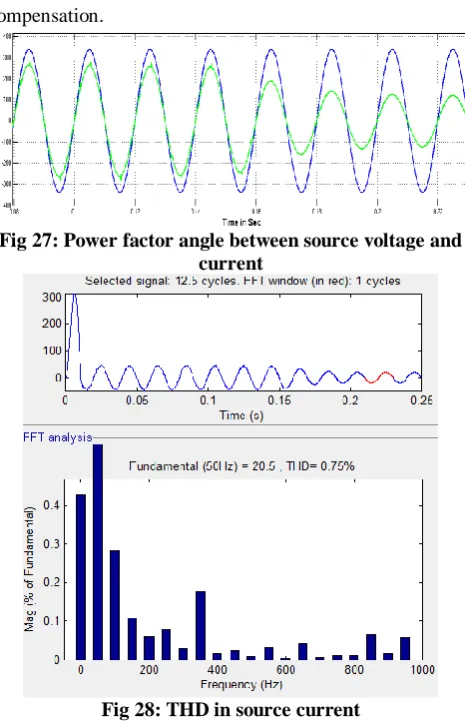
Fig 27: Power factor angle between source voltage and current
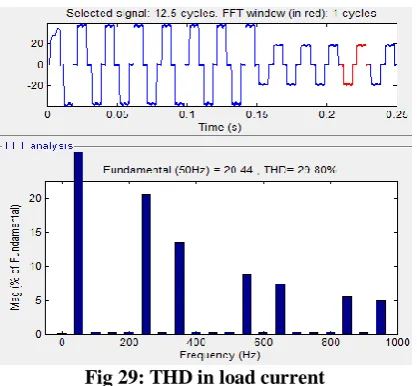
[image:5.595.48.294.459.542.2] [image:5.595.49.294.625.718.2]Fig 29: THD in load current
The angle between source voltage and source current is shown in figure 27. It is observed that there is no phase angle difference between these two; hence the power factor is nearly unity. The total harmonic distortion for source current is shown in figure 28 and the THD is 0.69% and the load current THD is 29.6% which is shown in figure 29. Load decrement conditions keeps harmonic in source current within nominal limits maintaining good power factor.
V. CONCLUSION
Parallel DSTATCOM concept is presented in the paper to mitigate the harmonics in power system line due to nonlinear loads in industries. D-Statcom is one of the custom power devices which is connected in parallel, and able to address the harmonics and reactive power issues in the power system line. The concept of parallel DSTATCOM has been introduced to reduce the switch ratings and switching losses. This parallel DSTATCOM configuration is controlled using instantaneous reactive power control theory. The proposed configuration was implemented by using Matlab/Simulink software and results are analyzed by changing loading conditions like increment in loading and decrement in loading. It is observed that there are no harmonic components in the source current. The required nonlinear component for load has been supplied by parallel DSTATCOM.
REFERENCES
1. Marcos Sacasqui, Jaime Luyo, Alexi Delgado, "A Unified Index for
Power Quality Assessment in Distributed Generation Systems Using Grey Clustering and Entropy Weight", ANDESCON 2018 IEEE, pp. 1-4, 2018.
2. J. Meyer, A. Blanco, S. Rönnberg, M. Bollen and J. Smith, "CIGRE
C4/C6.29: survey of utilities experiences on power quality issues related to solar power," in CIRED - Open Access Proceedings Journal, vol. 2017, no. 1, pp. 539-543, 10 2017.
3. R. Guzman L. G. De Vicuña J. Morales M. Castilla J. Miret
"Model-based control for a three-phase shunt active power filter" IEEE Trans. Ind. Electron. vol. 63 no. 7 pp. 3998-4007 July 2016.
4. M. Panoiu, C. Panoiu and L. Ghiormez, "Neuro-fuzzy modeling and
prediction of current total harmonic distortion for high power nonlinear loads," 2018 Innovations in Intelligent Systems and Applications (INISTA), Thessaloniki, 2018, pp. 1-7.
5. J. Rodriguez Maldonado, "Total Harmonic Distortion Estimation,
Minimization Inter Harmonic Amplitude and Expanding Bands Rejection in TKF filters," in IEEE Latin America Transactions, vol. 14, no. 2, pp. 652-656, Feb. 2016.
6. M. A. Chitsazan and A. M. Trzynadlowski, "Harmonic mitigation in
interphase power controller using passive filter-based phase shifting transformer," 2016 IEEE Energy Conversion Congress and Exposition (ECCE), Milwaukee, WI, 2016, pp. 1-5
7. D. Suresh, D. M. Rao and G. D. Sukumar, "Reduced rating hybrid
DSTATCOM for three phase four wire distribution system," 2016 IEEE 1st International Conference on Power Electronics, Intelligent
Control and Energy Systems (ICPEICES), Delhi, 2016, pp. 1-4.
8. B. Singh, M. Kandpal and I. Hussain, "Control of Grid Tied Smart
PV-DSTATCOM System Using an Adaptive Technique," in IEEE
Transactions on Smart Grid, vol. 9, no. 5, pp. 3986-3993, Sept. 2018
9. R. R. Chilipi, B. Singh and S. S. Murthy, "Performance of a
Self-Excited Induction Generator With DSTATCOM-DTC
Drive-Based Voltage and Frequency Controller," in IEEE
Transactions on Energy Conversion, vol. 29, no. 3, pp. 545-557, Sept.
2014.
10. G. Deep Srivastava and R. D. Kulkarni, "Design, simulation and analysis of Shunt Active Power Filter using instantaneous reactive
power topology," 2017 International Conference on Nascent
Technologies in Engineering (ICNTE), Navi Mumbai, 2017, pp. 1-6.
AUTHORSPROFILE
P.V.V. Satyanarayana was born in Andhra
Pradesh, India in 1967. He received the B.Tech and M.Tech degrees in Electrical and Electronics Engineering from JNTU Kakinada, Andhra Pradesh, India in 1993 and 2009, respectively. He also received the MBA degree from Osmania University, Hyderabad, India in 2013 and currently pursuing his Ph.D degree from Acharaya Nagarjuna University, Guntur. He has 20 years of experience in teaching and currently working as Associate Professor in the Department of Electrical & Electronics Engineering of Mahaveer Institute of Science and Technology, Hyderabad, India. His research interests include Electrical Machines, Power Systems, Power-Electronics, Non-Conventional Energy Systems, HVDC and FACTS.
Dr. P.V.RAMANA RAO was born in India in