CONTENT BASED VIDEO INDEXING AND RETRIEVAL USING
MOTION FEATURES
By
Warwick Gillespie
A dissertation submitted to the
School of Computing
in partial fulfillment of the requirements for the degree of
Bachelor of Engineering (Honours)
DECLARATION
This thesis contains no material which has been accepted for the award of any other degree or
diploma in any tertiary institution, and that, to the candidate’s knowledge and belief, the
thesis contains no material previously published or written by another person except where
due reference is made in the text of the thesis.
Signed:
ABSTRACT
Presented in this thesis is MPEG VIRS: A content based video indexing and retrieval system. It is a prototype system that allows the automatic population and indexing of a database of
MPEG-1 video files, based on colour, texture, and motion features. The system also allows
searching of the database via a graphical sketch. The main focus of this thesis is the
implementation of the motion indexing process, and additionally the integration of this
component into the system as a whole. MPEG VIRS is designed to display the potential of a content based indexing and retrieval system in the growing need to provide tools to aid the
management of large video databases, as well as to provide a framework for further research
ACKNOWLEDGEMENTS
I would like to acknowledge the following people who have helped me with my Honours
project (in alphabetical order):
Anh T Hoang
Philip Miller
CONTENTS
CHAPTER 1 - INTRODCUTION ... 6
CHAPTER 2 - CONTENT BASED VIDEO INDEXING AND RETRIEVAL ... 8
2.1VIDEO STRUCTURE ... 8
2.2MAIN COMPONENTS OF A VIDEO INDEXING AND RETRIEVAL SYSTEM ... 10
2.2.1 Database Population Interface ... 10
2.2.2 User Query Interface ... 11
2.2.3 Database and Matching Engine ... 12
2.3CURRENT SYSTEMS ... 12
2.3.1 VisualSEEK/WebSEEK ... 13
2.3.2 Query by Image Content (QBIC) ... 13
2.3.3 VideoQ [11]... 13
CHAPTER 3 - MPEG-1 FILE FORMAT ... 15
3.1MPEG-1FILE STRUCTURE ... 15
3.1.1 Frame Sequence ... 16
3.1.2 Intra Frame Coding... 17
3.1.3 Inter Frame Coding ... 19
3.2ANALYSING MPEG-1 FILES USING MPEG_STAT[5] PROGRAM ... 22
CHAPTER 4 - SYSTEM OVERVIEW ... 25
4.1THE SYSTEM ... 25
4.2THE POPULATION STREAM ... 26
4.2.1 Parsing of MPEG-1 File ... 26
4.2.2 Shot Detection ... 27
4.2.3 Colour Based Indexing ... 27
4.2.4 Texture Based Indexing ... 28
4.2.5 Motion Based Indexing ... 30
4.3THE DATABASES ... 31
4.4THE QUERY STREAM ... 32
4.4.1 Colour Query and Matching ... 33
4.4.2 Texture Query and Matching ... 34
4.4.3 Motion Query and Matching ... 34
4.4.4 Combining colour / texture / motion matches ... 34
CHAPTER 5 - MOTION BASED INDEXING AND RETRIEVAL ... 35
5.1OBJECT MOTION TRAJECTORY TRACKING TECHNIQUE [3] ... 35
5.1.1 Trajectory Indexing Process... 36
5.1.2 Trajectory Querying and Matching Process ... 38
5.1.3 Discussion of Trajectory Tracking Method ... 39
5.2ACTION /CHAOTICITY CLASSIFICATION METHOD ... 40
5.2.1 Definition - Amount of action ... 40
5.2.2 Definition – Chaoticity ... 40
5.2.3 Global Motion Indexing Process ... 40
5.2.4 Global Motion Matching Process ... 47
CHAPTER 6 - RESULTS & DISCUSSION ... 49
6.1RESULTS ... 49
6.2DISCUSSION ... 52
CHAPTER 7 - FUTURE SYSTEM IMPROVEMENTS ... 54
CHAPTER 8 - CONCLUSION ... 57
REFERENCES ... 58
CHAPTER 1
INTRODCUTION
The use of visual information is a part of every day life, and with the advent of technology
such as digital cameras, the amount of digital image and video data in the world is growing
rapidly. With this rapid growth comes the need for efficient management and storage of this
content, to enable users to maximise the effectiveness such data can have.
Currently, most large image or video databases can only be searched either manually (a
laborious task) or by text descriptions. While this process can be suitable in some situations
(such as small personal video collections) there are many downfalls to this method. Firstly is
the fact that a text description for every image or video has to be entered manually by a user,
making for a costly process for building the database (known as the population process). This
is especially unfavorable for large databases that exist with no indexing. Another drawback is
the fact that human influence on the population process will produce inconsistencies in the
indexing and searching as descriptions of the same video by two different people may be
vastly different.
The need for systems that can be populated automatically, and searched quickly and easily
has given rise to recent research efforts into content based indexing and retrieval systems.
These systems aim to populate image or video databases automatically with an index of
various features based on the content of the image or video.
MPEG VIRS (MPEG Video Indexing and Retrieval System) is a prototype system, aimed to provide users with the ability to search a video database to find videos with similar colour,
texture and motion characteristics as a simple sketch provided by the user. The current system
is a simplified prototype, aimed for use as a framework for further research.
This thesis describes the state of the system at present and recommends improvements, with
particular concentration on the author’s work into the motion aspect of the indexing process.
The thesis starts with a brief overview of the makeup of a content based image and retrieval
system (Chapter 2). This chapter presents how video is broken down into manageable
segments, the main components of a content based indexing and retrieval system, and a look
As the video files used in MPEG VIRS are in the MPEG-1 format, Chapter 3 gives a
description of this format. This includes an overview of the structure, the various compression
techniques, and finally how this compressed data is analysed by the mpeg_stat program[5] and used in MPEG VIRS for indexing purposes.
Chapter 4 gives an overview of the whole system, including how the colour and texture
indexing components work, how the databases are structured, and how the query and
matching process is implemented.
The main discussion of the author's work into the motion indexing process is in Chapter 5.
This includes a description of two techniques proposed for the motion indexing process. One
is an object based trajectory tracking technique, where as the other is a technique to describe
the global motion in a video. The results of these techniques and a discussion of the
performance the system as a whole is presented in Chapter 6.
Finally, Chapter 7 discusses the possible directions that future improvements to the system
CHAPTER 2
CONTENT BASED VIDEO INDEXING AND RETRIEVAL
The field of content based indexing and retrieval of images and videos is a fast growing and
relevant one in today's age of digital media. The reason for this research effort is due to the
rapid rise in the amount of digital images and videos being stored, especially in large
databases. The aim of content based indexing and retrieval systems is to provide quick and
easy mechanism of indexing and storing of visual content that will allow for easy searching
and retrieval by potential users of the content. The users of such systems may come from
varying domains, such as people browsing web content, media or advertising agencies
managing their visual data assets, or more specific applications such as face or finger print
recognition to aid police [12]. With such a broad scope of applications, the scope of a system
(i.e. what kind of querying it is designed to handle) is very important. The scope of this work
is investigating the use of content based indexing and retrieval systems for video management
or web browsing.
Although this field is still in the research stage (there are relatively few commercially
developed products working on images, and none working with video), there has already
developed a common system structure and standard terminology. This chapter will provide
background on previous work in this field, how a video is managed in these systems, an
introduction to the common structure of these systems, and also a brief discussion on how this
work fits into the picture.
2.1 Video Structure
One of the main concepts when dealing with a content based video indexing and retrieval
system (as opposed to a still image system) is how a video sequence can be broken into
manageable segments. Obviously, when attempting to index and retrieve video, it would be
impractical, and unsuitable to index full video sequences (for example a two hour long movie)
at once. The video sequence needs to be broken down into shorter lengths. This aim of video
indexing systems is to perform this segmentation automatically, and based on the video
content rather than on simple time measures.
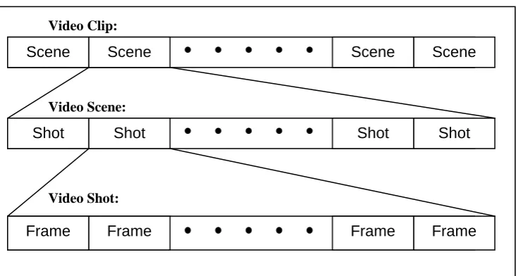
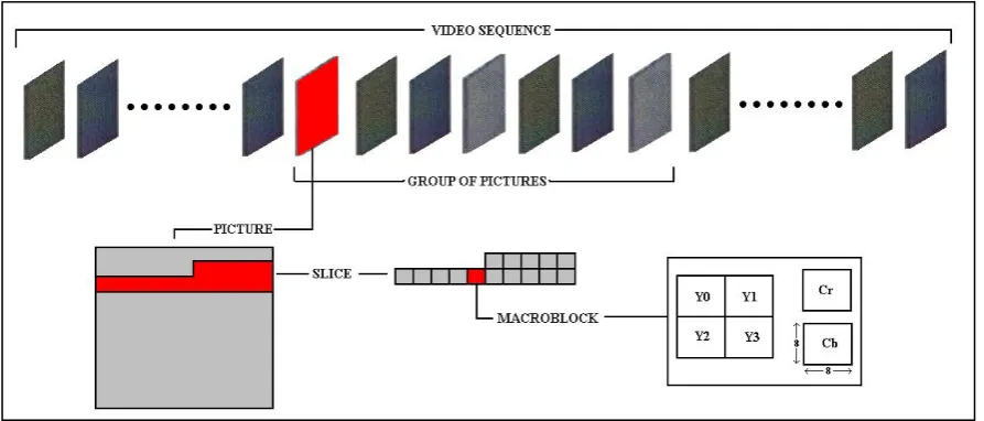
Figure 2.1 Structure of a video clip
The breakdown of a video clip into segments (each of smaller time frame) is shown in Figure
2.1. The following is a description of each segment:
A video clip is considered to be a full video sequence (such as a whole movie). As a
result, the time frame for a video clip can range from seconds to hours. Due to the large
time frame, it is usually unsuitable to use whole clips for indexing purposes. A video clip
is made up of one or more video scenes.
A video scene is a section of video depicting a single story, scene, or event in a video clip.
A video scene is made up of a number of shots and may have a time frame ranging from
seconds to minutes. Video scenes can be useful in the management of video data.
A video shot is the most important unit of video segmentation when it comes to video
indexing. A shot is simply the portion of video between two camera breaks (such as a cut,
or a fade). The shot generally shows a single cameras perspective of a scene and has a
time frame of a few seconds. Video shots are made up of many video frames.
A video frame is the basic temporal unit in a video. A frame is like a still image of a scene
at a given time. A frame time unit is constant for a given video clip, and is generally a
small fraction of a second. Although the information for indexing is extracted from
frames, they are too short to be used as a segmentation level for searching.
Scene Scene Scene Scene
Shot Shot Shot Shot
Frame Frame Frame Frame
Video Clip:
Video Scene:
2.2 Main Components of a Video Indexing and Retrieval System
The majority of content based indexing and retrieval systems (image or video) are made of
three main components:
Database Population Interface
User Query Interface
Database and Matching Engine
The basic functions of these three components are also fairly common for all systems.
2.2.1 Database Population Interface
The database population interface is where the preprocessing of video files in order to store
them in the database. In the case of a web based retrieval system, this process can be
performed off-line. The purpose of this process is to index each video clip to be stored in a
[image:10.595.90.513.467.574.2]database that can then be searched quickly and easily by the user.
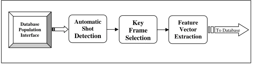
Figure 2.2. Database Population Interface Flowchart
As can be seen in Figure 2.2, the three main processing steps in the population component
are:
automatic segmentation (shot detection) key/representative frame selection feature vector extraction and indexing
Database Population
Interface
Automatic Shot Detection
Key Frame Selection
Feature Vector Extraction
2.2.1.1 Automatic Segmentation
The automatic segmentation process will break down a video clip into smaller segments
called shots (Section 2.1). The further processing in the system will be done on a shot by shot
basis.
2.2.1.2 Key frame selection
For most features, the indexing for each shot is performed on a single representative or key
frame (often termed an r-frame). The selection of this frame can effect the success of
indexing. Some common selection techniques include using a random frame from a shot,
using the first frame from a shot, although more complex methods (such as using frames with
least motion) have been proposed.
2.2.1.3 Feature Extraction and indexing
The feature extraction and indexing is performed for each detected shot in a video clip. Many
features (such as colour, texture, and shape) are extracted from r-frames using similar
techniques as in image based systems. Other features (such as motion) have to be extracted
across the whole shot. An index of each feature, for each shot is then stored in the database
for later searching.
2.2.2 User Query Interface
The user query interface is the component of the system that is used to search the database of
indexed video files and based on the results, retrieve the desired video content. The makeup
of the user query can depend on many things, such as the type of content being searched for,
the process by which the video clips are indexed, and the environment the system is running
in.
In terms of colour and texture indexing and retrieval, there are two main methods prevalent in
the development of systems. The first is Query by Example, the second is Query by Sketch. In Query by Example, the search is executed by presenting the matching engine (via the user
query interface) an image that is used as the basis for the search. The search is performed by
calculating the same feature vectors on the image presented as a query, and then compared
frames) which have the closest matching feature vectors. These returned matches can usually
be used as inputs for further searches to attempt to refine the search. The Query by Sketch
interface allows the user to draw a simple sketch of the image to be searched for. This sketch
is used as the input to the search and the same process is performed as in Query by Example.
Once again the sketch can be further refined based on the images / frames returned on the
initial search.
The query of motion is a process which is still very much in the research stage (as most
current systems are based on images rather than videos), but currents efforts generally are
focused on the tracking the trajectories of objects through a shot (see Section 2.3.3).
2.2.3 Database and Matching Engine
The database and matching engine component of the system is the link between the two other
components in the system. The population component obviously needs to interact with this
component to build the database, and the query component similarly needs to access the
indexed database in order to perform the matching and retrieval.
Although much of the research currently being performed is focused primarily on the other
two system components, as this develops the structure of the database and matching engine
becomes more and more important. This is because as systems become more accurate, the
databases that they are used upon will become significantly larger (especially when
considering the rapid rise in the amount of digital images and videos). As a result, the
database structure would become a concern in order to reduce searching time, especially in
web based systems.
2.3 Current Systems
As stated above, most current content based indexing and retrieval systems work on still
images not video, and certainly all commercial products are image based systems. Three
important systems are Query by Image Content (QBIC), VisualSEEK \ WebSEEK, and
VideoQ. Other commercial systems available include Virage’s VIRImage Engine, and
market place, with both the Alta Vista and Yahoo! Search engines containing content based
retrieval facilities, courtesy of Virage and Excalibur respectively [12].
2.3.1 VisualSEEK/WebSEEK
VisualSEEK and WebSEEk are two developmental image based systems produced by
Columbia University (an important player in the research into content based indexing and
retrieval systems).
VisualSEEK is one of the first system developed, and could be used to index still images
based on a combination of colour, location and a simple text description. WebSEEK has
similar properties to VisualSEEK, and was developed primarily to allow querying via the
web. Both VisualSEEK and WebSEEK are query by example type systems.
2.3.2 Query by Image Content (QBIC)
The QBIC system, developed by IBM, is a still image based system and was one of the first to
be commercially released. QBIC can be queried using either an example image, or by
generating a sketch, or by selecting certain colour/texture patterns. The QBIC system indexes
images based on colour, texture, shape, and by a simple text description.
2.3.3 VideoQ [11]
VideoQ is one of the only demonstration systems developed that performs content based
indexing and retrieval on video rather than simply still images. It is another developmental
system produced by Columbia University. The aim of VideoQ was to provide [11] :
Automatic video object segmentation and tracking.
Query with multiple objects, based on features such as color, texture, shape, size and
motion.
Spatio-temporal constraints on the query.
Interactive querying and browsing over the World-Wide Web.
A user query to VideoQ is performed via an ‘animated sketch’ where each object drawn in a
sketch (like any sketch for a still image system) can be assigned motion. The motion query is
in the form of an N point trajectory. Also the arrival sequence of objects, the speed, and
length of the motion trajectory can be set.
The most significant feature (compared to other systems) is the addition of motion to the
feature query base. The VideoQ system uses colour regions and edge techniques to segment
objects in each frame of video, and then uses optical flow techniques to track the objects
throughout a shot.
Although VideoQ is not to a standard that would allow commercial sale, it certainly provides
a good indication of the potential of content based indexing and retrieval system for video
data. It also displays the potential of combining many different features into a single search in
CHAPTER 3
MPEG-1 FILE FORMAT
Like most digital information at present, digital video comes in many different formats, and as
such a standard needed to be chosen for this system. The MPEG-1 file format was chosen
because of three main reasons [1][2]. Firstly, it contains information encoded in the bit stream
that can be used directly in the indexing process. Secondly, there is existing software to
analyse an MPEG-1 bit stream [5]. Finally the file size is manageable, and hence would be
suitable for use over a medium such as the Internet. Because the MPEG-1 file is a compressed
format, a description of the compression techniques used, and the structure of the bit stream
produced is necessary.
3.1 MPEG-1 File Structure
The MPEG-1 file has a hierarchical structure, like many computing based protocols, with
each layer providing a different level of abstraction. The higher levels of MPEG-1 (such as
the Multiplexed Stream, the Pack, and the Packet layer) provide for the ability to have a
number of different video and audio streams in the one file, and also control the
synchronisation of these multiple streams. Currently MPEG VIRS is only used on files with a single video stream (no audio) so these higher layers are not relevant to the system.
The lower five layers (the Video sequence, Group of Pictures, Picture, Slice, and Macroblock
[image:15.595.78.525.561.752.2]layer) however are used as they control the coding and decoding of a single video stream.
The video sequence layer packages a whole video stream together and contains
information about the whole stream (such as frame size, pixel aspect ratio, frame rate, bit
rate, buffer size, and any relevant quantisation tables).
The group of pictures layer packages together groups of frames. This layer allows random
access to the video stream.
The picture layer contains information to a specific frame, such as the type, and any
parameters needed for buffering, and the encoding parameters used, like the resolution of
motion vectors (e.g. half or full pixel).
The slice layer segments the picture layer into a number of different groups of
macroblocks. This allows each slice to have a different quantisation scale, to allow some
slices to be coded more accurately than others.
The macroblock layer contains the actual information about each macroblock, such as the
type, any motion vectors, the coded block pattern, and the six 8x8 blocks Y0 ..Y3, Cr, Cb.
3.1.1 Frame Sequence
The basic and most important unit of any video coding standard (including MPEG-1) is the
frame. In the MPEG-1 standard there are three different types of frames defined, I-frames,
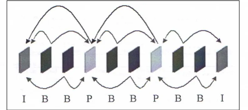
[image:16.595.101.498.573.750.2]P-frames and B-P-frames.
The I-frames (or intra coded) are coded with no reference to any other frame. They are treated
like a still image, and are used in order to stop errors propagating through the video stream,
and also to allow random access to the video stream. I-frames achieve a compression rate of
about 7:1.
The P and B-frames (or inter coded) are coded with reference to other frames. P-frames
(predictive) only reference a past I or P frame (as shown in Figure 3.1). P frames can achieve
a compression ratio of about 20:1. B-frames (bi-directional) are coded with reference to both a
past and a future I or P frame (as shown in Figure 3.1). B-frames can achieve a compression
ratio of about 50:1.
Due to the fact that B-frames are coded with reference to both past and future frames, the
[image:17.595.154.440.369.502.2]frame display sequence has to be different to the frame decoding sequence.
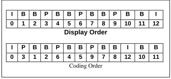
Figure 3.2. Differences between coded and display order
The difference in the display and decoding order can be seen in Figure 3.2. For instance the
B-frames 1 and 2 are produced with reference to the past I-frame 0 and the future P-frame 3.
As a result, when decoding the bit-stream, both frame 0 and 3 would be decoded and buffered
first for use when decoding frames 1 and 2.
3.1.2 Intra Frame Coding
As described above, intra coded frames have no reference to any other frames. As a result, the
compression techniques used have to remove any spatial redundancies within a frame. The
seven main steps in the coding of an I-frame are:
I B B P B B P B B P B B I
0 1 2 3 4 5 6 7 8 9 10 11 12 Display Order
I P B B P B B P B B I B B
Colour space conversion (RGB YCrCb)
Frame divided into blocks
Discrete Cosine Transform (DCT) on each block
Quantising
Zig-zag scanning
DPCM on DC & RLE on AC components
Huffman / Arithmetic coding
The colour space conversion converts the frame from the RGB to the YCrCb colour space.
This is to take advantage of human perception to reduce the amount of data stored. In the
RGB colour space, an R (Red), G (Green), and a B (Blue) value represents each pixel in an
image. Usually each value is stored using 8 bits, resulting in each pixel needing 24 bits for
storage. In the YCrCb colour space the Y (luminance) component represents the intensity
information (or grey level), and the Cr and Cb component represents the chrominance (or
colour). The human visual system is more sensitive to the luminance component than the
chrominance components, so they can be subsampled at Y:CR:Cb = 4:1:1. Using 8 bits for
luminance, this means only 2 bits are needed for each of the chrominance components,
resulting in each pixel only needing 12 bits for storage (half that of the RGB format). The
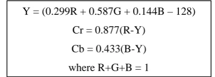
[image:18.595.186.403.462.540.2]conversion from RGB to YCrCb is performed as follows:
Figure 3.3 Formulae for Colour Space Conversion
Once the colour space conversion is done, the frame is broken down into macro blocks and
blocks. The macro blocks consist of one 16x16 pixel Y component block, one 8x8 pixel Cr
block, and one 8x8 pixel Cb block. The remaining steps in the coding process are performed
on 8x8 blocks, (i.e. for each macro block there are four 8x8 pixel blocks for the Y component,
one 8x8 block for the Cr component, and one 8x8 pixel block for the Cb component).
The next two steps in the coding provide the greatest compression, as they are lossy (some
information is discarded). The DCT converts each block in a frame from the spatial domain to
the spatial frequency domain. As a result all that needs to be stored is the coefficient of each
Y = (0.299R + 0.587G + 0.144B – 128)
Cr = 0.877(R-Y)
Cb = 0.433(B-Y)
frequency component (for an 8x8 pixel block there will be 8x8 frequency components). The
DCT compacts the energy into the lower frequency range, so these coefficients can be further
compressed. The coefficients are quantised, and those below a certain threshold (which
human perception cannot distinguish) are discarded.
The final three steps take advantage of the typical arrangement of DCT coefficients
(compacted into the DC component and low frequency band) and other statistical quantities.
Zig-zag scanning is a process which orders the coefficients from the DCT in such a way that
there is a high likelihood that consecutive zeros will occur. This is because most of the higher
frequency components have been thresholded to zero. The entropy coding uses a statistical
technique of encoding commonly occurring values with small code words, and less often seen
values with longer code words.
For greater detail on the coding of I frames, see references [1], [8] and [9].
3.1.3 Inter Frame Coding
As stated above, the main function of the inter coded frames (P and B frames) is to take
advantage of temporal redundancies. The MPEG-1 coding process uses motion vectors in
order to do this. For each macroblock in a P or a B frame, a search window in a reference
frame (or frames) is examined to find a similar block. If a similar macro block is found, a
reference to it (the motion vector), as well the difference between the actual and the reference
macroblock is coded. As the difference is usually small, the coding of this and the motion
vector will take less space than the coding of the whole macroblock. As a result, the
compression rate is increased.
3.1.3.1 Motion vector search techniques
As the majority of compression in P and B frames is delivered by the use of motion vectors,
the technique used to find the best motion vector is important. The object of a motion vector
search algorithm is to find the best match for the macroblock being coded within a search
Figure 3.4 Motion Vector Search [1]
The two performance criteria for a motion vector search algorithm are the ability to find the
best match (producing the least difference between the current and reference macroblock),
and also the computation time needed to perform the algorithm.
The optimal search technique is known as the full search, in which the current macroblock is
compared with every possible macroblock in the search window. The closest match is usually
obtained by finding the reference block resulting in the least mean square difference:
21 0 1 0 ) , ( ) , ( 1 ) , (
M k N l j l y i k x R l y k x T N M j i MSDwhere T(x + k, y + l) = pixel at (k,l) from top left hand corner (x,y) of Target block
R(x + k + I, y + l + j) = pixel at (k, l) from top left hand corner (x + i, y + j) of
reference frame
(i, j) is motion vector from top left hand corner of target frame to the left hand corner
of reference frame
Note that the search window is MxN (i.e. not necessarily square) because motion vectors are
typically larger in the x (horizontal) direction. It should also be noted that other methods
could be used to calculate the best matching reference macro block (such as the mean absolute
difference, pel difference classification, and integral projection)[8].
Reference Frame (previously decoded I or P frame)
Target Frame (current P frame)
Search Region
Target Block
The optimal technique will find the best possible match, but is computationally expensive.
Other sub-optimal techniques can be used which do not compare the target macroblock with
every possible macroblock in search window, but a select few.
The first sub optimal technique is to compare the MSD for a set number of evenly spaced
macroblocks around the target macroblock. The macroblock with the closest match is then
used as the centre of the next level of search, using the same technique in a smaller area. This
takes advantage of the principle of locality (macroblocks with very good matches are likely to
be close to macroblocks with good matches) in order to select which macroblocks to compare.
Some algorithms using this format are the two dimensional logarithmic search, the three step
search, and the orthogonal search algorithm [8].
A second sub optimal technique uses down sampling (so there are less pixels in each
macroblock) of the original image to perform the first full search. The macroblock with the
closest match is then used as the centre of the next full search, in a smaller window, and with
a slightly higher sampling rate. This process can continue a number of levels of down
sampling to increase the accuracy of the final motion vector. This method is called
hierarchical motion estimation.
A final method is to first perform a full search using a less accurate, but computationally
inexpensive matching method (such as the pel difference classification). The block with
closest match is then used as centre for next full search, in a smaller window but using a more
accurate matching technique (such as the MSD). As a result, the more accurate, but time
consuming matching technique is used on less macroblocks. This technique is known as a
signature based algorithm [8].
3.1.3.2 Macroblock Types
One of the keys to the compression rates achieved by MPEG-1 is due to the number of
different coding techniques used in different situations in the process. In fact, unlike I frames
(in which every macroblock is intra coded), macroblocks in P and B frames can be coded
quite differently within a single frame. The following is a brief description of the different
Intra
Even in P and B frames, if a close enough match cannot be found in the motion vector search,
then the macroblock can be intra coded (in the same fashion as all the blocks in an I frame).
These macroblocks occur in both P and B frames.
Skipped
If a macroblock does not change between the reference and the frame currently being coded,
then the coding of that block can be skipped. This would correspond to finding a reference
block in the motion vector search with motion vector (0,0) and error term of 0. These
macroblocks occur in both P and B frames.
Forward
Forward coded macroblocks contain motion vector information referring to a past frame (ie
the most recent I or P frame in the past). These macroblocks occur in both P and B frames.
Backward
Backward coded macroblocks contain motion vector information referring to a future frame
(i.e. the most recent I or P frame in the future). These macroblocks only occur in B frames
Interpolated
Interpolated macroblocks are coded with reference to both a past and a future frame. This is
done by producing the least prediction error after averaging a macroblock in the past
reference frame with a macroblock in the future reference frame. These macroblocks only
occur in B frames
3.2 Analysing MPEG-1 files using mpeg_stat[5] program
As described in this chapter, the MPEG-1 file format contains information about the colour,
and motion present in a frame of a clip. It also contains DCT coefficients, which can be used
for texture classification. The mpeg_stat [5] program is a command line program which parses an MPEG-1 file (only the video stream is examined) and produces various text file
outputs containing different statistics relating to the MPEG-1 file. The statistics that can be
general characteristics (such as number of frames, frame size, compression ratio and
quantisation scale for each frame type)
bit-rate at every picture
block level information (thoroughly describes how each macroblock is coded, including
block type, motion vectors, and optionally the DCT coefficients)
In MPEG VIRS the following call to mpeg_stat is used:
mpeg_stat -block_info [output text file name] [input mpeg file name]
which writes macroblock level information about the MPEG-1 file 'mpegfile.mpg' into the
text file 'blkfile.txt'. Also the system output is piped to a separate text file to store the general
[image:23.595.117.484.334.547.2]characteristics of the MPEG-1 file.
Figure 3.5 Sample text file output from mpeg_stat program
The above diagram (Figure 3.4) shows part of a text file containing macroblock level
information about an MPEG-1 file. The MPEG VIRS population stream parses this file in order to perform shot detection, and feature vector extraction.
Line 1 displays the frame number, frame type (I, P, or B), and motion vector unit (full or half pixel)
Line 2 gives the slice number and the quantisation factor for that slice
the remaining lines show the information given for each macroblock (the macroblock
number, the frame type, the quantisation factor, the macroblock size in bits, and the type)
1 2 3
4 5 6 7
8 9 10
11
12
frame 0 I none 2 slice 1 9
block 0 I 9 61 intra
…..
frame 1 B half 0 slice 1 13
block 0 B 13 14 back <8, 4>
block 1 B 8 59 forw+back <8, 0> <8, 4> 001100
…..
frame 6 P half 8 slice 1 15
block 0 P 15 14 forw <8, 4>
……
block 36 P 9 0 skip …..
Line three shows the macroblock type is intra (as expected for an I-frame) Line 4 shows start of new frame (type B)
Line 6 shows a macroblock coded with a motion vector referencing a future frame. The
value of motion vector is (8, 4)
Line 7 shows an interpolated macroblock coded with a motion vector of value (8, 0)
referencing a past frame and a motion vector of value (8, 4) referencing a future frame.
The 6 bit binary string after the motion vectors is the coded block pattern, which shows
which blocks (of the four Y, the Cr, and the Cb blocks) are coded (1) or not (0).
Line 8 shows start of new frame (type P)
Line 11 shows a skipped macroblock. In VIRS they are treated like macroblocks with
CHAPTER 4
SYSTEM OVERVIEW
As described in Chapter 2, there are three main components of a content based indexing and
retrieval system (the population stream, the query stream, and the indexing and retrieval
stream). In MPEG VIRS, the indexing and retrieval stream is combined with both the query and the population stream. While the author’s efforts were focused on the motion indexing
side of the system, it is important to include an overview of the system as a whole. This
chapter includes a description of the indexing and matching methods, the structure of the
database, and the user query interface.
4.1 The System
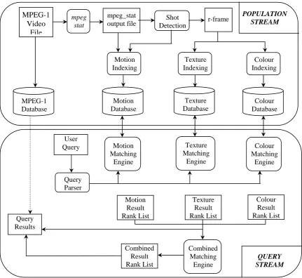
[image:25.595.85.517.336.732.2]The following diagram shows the data flow through the system
Figure 4.1. Data flow through entire system
4.2 The Population Stream
The population stream of the system is responsible for parsing an MPEG-1 file (through the
use of the mpeg_stat program). After this is done, the population stream performs the shot
detection, the r-frame generation, the feature vector extraction (for colour, texture and
[image:26.595.91.504.213.374.2]motion), and also provides the user interface to the index and database generation.
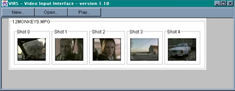
Figure 4.2 Graphical User Interface for Population stream
The above figure shows the user interface for the population stream. The images shown are
the r-frames of the shots detected for the already processed MPEG-1 file "12MONKEYS". The three buttons (New, Open and Play) are used to either process a new MPEG-1 file, open a
previously processed MPEG-1 file, or to play an already opened MPEG-1 file.
4.2.1 Parsing of MPEG-1 File
As described in Chapter 3, in order to acquire the necessary block level information in an
MPEG-1 file for indexing purposes, the mpeg_stat [5] program is used. This program parses the MPEG-1 file and generates text files containing the necessary information, from general
characteristics down to macro-block level information such as motion vectors (see Section
3.2). These text files can then be parsed by the system in order to perform shot detection and
4.2.2 Shot Detection
The current system implements a shot detection method that is designed to detect abrupt or
sudden shot transitions (but not gradual ones such as fades or wipes). The shot detection
algorithm is an implementation of a method proposed by Fernando et al [10]. It is a method
that works entirely in the compressed domain, by using the number of interpolated
macro-blocks in B-frames in order to detect the shot transitions. For a more detailed description of
this, see Burgess' thesis [1] or Horswill's thesis [2].
4.2.3 Colour Based Indexing
The colour matching component of the system was implemented by Burgess [1] and Horswill
[image:27.595.88.512.316.543.2][2]. The following diagram (Figure 4.3) describes this process:
Figure 4.3 Flowchart for colour indexing process
The steps involved in the process are described as follows:
As a result of the shot detection process, each shot identified will have an r-frame generated to represent that shot.
The r-frame is then converted from the RGB (Red, Green, Blue) colour space to the HSI
(Hue, Saturation, Intensity) colour space. This is done because the HSI space is based on
the human perception of colour, which is used in the next step.
RGB
r-frame
HSI r-frame
10 Colour r-frame
Colour Space Conversion
r-frame Quantisation
r-frame Segmentation
The r-frame is then quantised into ten different colour bands. This is done by grouping
ranges of colour that are similar to the human eye into a single representative colour (a
simple operation in the HSI colour space).
The r-frame is then segmented into nine equal regions in order to introduce an element of
spatial locality to the colour indexing.
Finally the fraction of each colour in each region is calculated and stored in a 9x10
two-dimensional array (9 rows for each of the regions, and 10 columns for each of the
colours). This index array is stored for each r-frame in the colour database.
4.2.4 Texture Based Indexing
The texture indexing component of the system was implemented by Miller [14]. The
[image:28.595.84.496.404.636.2]following diagram (Figure 4.4) describes this process:
Figure 4.4 Flowchart for texture indexing process
The steps involved in the process are described as follows:
The RGB r-frame is converted to a grey scale r-frame. This is an image that contains no
colour, only 256 different grey levels. This step is performed as the texture information in Grey
Scale r-frame
Colour Space conversion
D.C.T Feature
Vector Fisher
Discriminant Analysis
Feature Vector Calculation Hierarchical
Splitting
Polygon Merging
RGB r-frame
Texture Index Segmentation
an image is contained only in the intensity (grey level) component of an image, not in the
colour component.
The grey scale r-frame is then processed using a hierarchical splitting algorithm in order
to segment the r-frame into regions of common texture. The hierarchical splitting
operation is an iterative process designed to break down the image into smaller and
smaller regions of the same texture. The basic algorithm is :
1) split the r-frame into equal size blocks
2) split each block into four smaller sub-blocks
3) For each block the feature vector classification step is performed on each of the
smaller sub-blocks.
4) If the four sub-blocks have the same texture classification, the block is not split
any further.
5) If the sub-blocks do not have the same classification, then the process is
repeated, breaking down the sub-blocks into even smaller blocks.
6) This process continues until either every block (of varying size) has been
assigned a texture, or until each of the blocks is broken down into a minimum
size.
The classification step performed above is a two part process. The first is the calculation of a texture feature vector. This is done by performing a discrete cosine transformation
(DCT) on the block being classified, but discarding the DC term. The DCT coefficient
matrix is then segmented into 4x4 equal sized regions. The feature vector is then simply a
sixteen element array, with each element containing the sum of the DCT coefficients in
each of the sixteen segmented regions. The second part of the classification process uses
Fisher Discriminant Analysis to classify the feature vector into one of eight different textures. Fisher Discriminant Analysis groups feature vectors of the same class (i.e. the
same texture) together, and separates feature vectors of different classes (for full
descriptions of these classification steps see Miller [14]).
Once the whole r-frame has been classified into many small blocks of texture, these small
merging simply compares adjacent blocks, and if they contain the same texture, will be
grouped into the same region.
Finally an index of the textures present in the r-frame is calculated. Like the colour
indexing this is done by segmenting the r-frame into nine equal regions and calculating
the fraction of each texture in each region. This is then stored in a 9x8 two dimensional
array (9 rows for each of the regions, and 8 columns for each of the textures). This index
array is stored in the texture database for all r-frames.
4.2.5 Motion Based Indexing
The motion based indexing implemented in the system is a global based technique, which
describes the motion within a video shot in terms of the action (the amount of motion), and the chaoticity (the smoothness of motion) across the whole shot (for full definitions see Sections 5.2.1 and 5.2.2).
[image:30.595.97.508.379.590.2]
Figure 4.5 Flowchart for motion indexing process
The action calculation is determined by summing the types of macroblocks within a shot
(i.e. blocks with similar motion vector magnitudes, or all intra coded blocks). These
values are expressed as a percentage of the total number of macroblocks in the whole shot
(for full description see Section 5.2.3.4 ).
mpeg_stat ouput file
Shot Detection
Action Calculation
Chaoticity Calculation
Motion Feature Vector
Classification using RBF
Motion Index
D1
The chaoticity calculation is determined by examining the direction of motion vectors
within the frames of a shot. The number of macroblocks with similar motion vector
directions are summed, and expressed as a percentage of the number of macroblocks with
non (0,0) motion vectors within a frame. The value for chaoticity describes whether most motion vectors are in a similar direction, or for chaotic motion, the directions are varied
(for full description see Section 5.2.3.5).
The motion feature vector (the pair of action and chaoticity values) is then presented to a
Radial Basis Function Network (RBF) which classifies the feature vector into one of nine
motion categories (corresponding to high, medium or low action and chaoticity). The RBF
network has nine clusters with known centres and variances, each cluster containing all
feature vectors of the same motion type. The RBF Network produces the motion index
which is a nine element array, each element being the distance from the feature vector to
the centre of one of the clusters (for full description see Section 5.2.3.6).
4.3 The Databases
The current system contains five different databases.
MPEG-1 File Database: The MPEG-1 files indexed in the system are all stored in one
database, which can be accessed (for viewing of file), based on the query results presented
by the system.
r-frame Database: The r-frame database contains all the representative frames for all the
shots detected for the files in the MPEG-1 database. This database is used for colour and
texture indexing, and also for the display of the query results.
Index Databases: The other three databases contain the indexes for the three content
features in the system (colour, texture and motion). The Population stream builds the
databases, and the Query stream accesses them in order to perform the matching process.
Each of the index databases is a simple text file containing the index for each shot in the
database. The colour database contains the colour index (the 9x10 matrix described in
two step process. First an MPEG-1 file has to be added to the database, by using the New
button in the Population interface (see Section 4.2). This will detect the shots present in the
MPEG-1 file and for each shot create an r-frame and add it to the r-frame database. The
second step, once all MPEG-1 files have been added, is to compile the index database. This is
done by running the java file ImageSegmenter.java from the Jcreator Java development environment. This file will perform the colour indexing process on each of the r-frames in the
r-frame database, and store the indexes in the colour index database.
Similarly, the texture database contains the texture index (see Section 4.2.4) for each shot in
the r-frame database. The creation of the texture database is also a two step process, similar to
the creation of the colour database. The first step is the same (to create the r-frame database),
and the second is to run the java file TextureSegmentation.java, which will perform the texture indexing process on each of the r-frames in the r-frame database, storing the indexes
in the texture index database.
The motion database is created by first performing the same first step as above. This will, in
addition to building the r-frame database, create a file with all the feature vectors for all the
shots in the r-frame database (the motion indexing does not use the r-frames directly). This
file of feature vectors is then used as the input to a Matlab program (see Appendix 1). The
Matlab program performs the RBF classification step in the motion indexing process. For each feature vector, the program calculates the distance from the feature vector to the centre
of each cluster. These distances are then stored in the motion index database.
4.4 The Query Stream
The query stream of the system is the part of the program that a user can use to search the
database for a desired video clip. The search is via a simple sketch by the user, which is
processed in the same fashion as the r-frames, to produce a query feature vector for both
colour and texture. The global motion for a query can be entered via check buttons below the
Figure 4.6 Graphical User Interface of Query stream
4.4.1 Colour Query and Matching
As stated above the user can enter a sketch in the user query interface containing various
shapes and assign colours to each shape. This simple sketch is processed in exactly the same
way as each of the r-frames in the database to produce a query feature vector. The query
feature vector is of the same format as the indexed feature vector (ie a 9x10 matrix containing
the percentage of each of the ten colours in each of the nine regions).
In order to produce a ranked list of matching shots, the difference between the query feature
vector and each of the index feature vectors in the colour database is calculated. A list of the
best matches (the length of which can be specified by the user) is returned, with the r-frames
of the best matches displayed for the user. The user can then click on any of these r-frames to
view the corresponding shot from the file in the MPEG-1 database. 1
2
3 4
5
6
8 7
4.4.2 Texture Query and Matching
The texture query matching process is similar to the colour matching process. The user can
assign (along with a colour) a texture to each of the objects drawn in the user sketch. The
texture indexing process is performed on the query sketch, producing a query feature vector
of the same form as the texture index database (containing the percentage of each of the eight
textures in each of the nine regions). The difference between the query vector and all the
indexed vectors in the database is calculated, and a ranked list of the best texture matches is
returned. By clicking on the texture tab in the user query interface (see Figure 4.5), the user
can view the r-frames of the best texture matches.
4.4.3 Motion Query and Matching
The motion matching is done simply by the user selecting the desired level of action and
chaoticity for a shot via the buttons under the sketch canvas (see Figure 4.6). This can be used
by the motion matching engine to determine which cluster in the RBF the shot should belong
too, and hence the distance from each shot to the desired cluster can be extracted from the
motion index database. A ranked list of the best matches is returned, and the user can view the
r-frames of the best matches by clicking on the Motion tab in the user query interface (for full
description see Section 5.2.4).
4.4.4 Combining colour / texture / motion matches
While the results of colour, texture, and motion can be viewed separately, it is also possible to
combine these search results together. In the current implementation of VIRS, this is simply
done by merging the ranked query lists together. This technique was used primarily to
investigate the ability of the motion query to be used as a means of refining a query result
based on colour. To do this, only the motion and colour query results were merged, by simply
placing all shots that occurred in the top five of both the colour and the motion match lists
into a list of combined positive matches. The texture results were not merged in order to
CHAPTER 5
MOTION BASED INDEXING AND RETRIEVAL
As mentioned in Chapter 4, the author's efforts were focused on the implementation of motion
feature indexing. The main objectives of the techniques discussed in this Chapter were
twofold. The first was to provide a mechanism that is easy to understand from the user's point
of view when searching (i.e. a technique that matches the human perception of classifying
what motion occurs within a video shot). The second was to be able to perform the indexing
in the compressed domain (i.e. use the motion vector information present in an MPEG-1 file
to describe the motion of a video shot).
Two techniques for motion indexing were investigated. The first was an algorithm similar to
the VideoQ [11] system (see Section 2.3.3) that attempted to track the motion trajectory of
objects within a video shot. The second technique applied a slightly higher level of
abstraction in describing the motion within a shot. Using statistical means, the second
technique attempted to calculate a global motion perception for a shot, in terms of the amount
of action and the chaoticity of the action.
5.1 Object Motion Trajectory Tracking Technique [3]
As mentioned above, the first technique investigated attempted to index the motion
trajectories of significant objects within a video shot. The fundamental approach was to first
identify objects within frames. The object segmentation was performed by grouping regions
of macroblocks with similar motion vectors. The objects would then be tracked across
multiple frames in order to create a motion trajectory for the object across a whole shot. It
should be noted that, for two reasons, only p-frames were used in this process. The first was
to decrease the number of frames an object has to be tracked across (to reduce computation
time), and secondly because all motion vectors in P-frames point in the same direction (i.e.
they all reference the most recent I or P frame in the past). I frames cannot be used as they
contain no motion vector information, and B-frames cannot be used as the presence of too
many interpolated macroblocks would probably degrade the performance of the indexing
5.1.1 Trajectory Indexing Process
The object trajectory tracking technique is basically a four step process:
Extraction, quantisation, and filtering of motion vector field Clustering of motion vector field
Object extraction
Trajectory tracking and Indexing
5.1.1.1 Extraction, quantisation, and filtering of motion vector field
The motion vector field for each p-frame within a video shot is extracted straight from the
output text file produced by the mpeg_stat[5] program (see Section 3.2). The motion vector
field for a frame is simply a 2-D array with the same number of rows and columns as the
width and height of the frame (in number of macroblocks). Each element in the array contains
the motion vector for the corresponding macroblock in the p-frame. Intra coded macroblocks
are given invalid (out of range) motion vector values so they can be identified as intra coded
blocks. As stated in Section 3.2, skipped macroblocks are assigned a motion vector (0,0).
The motion vectors in the motion vector field are integers corresponding to the horizontal or
vertical magnitude in either half or full pixels (most frames are half pixels). From the output
of the mpeg_stat program, the maximum magnitude (in half pixels) can be found for a given MPEG-1 file (in both the horizontal and vertical direction). For each frame it can also be
found whether the motion vectors are coded at a level of either full or half macro-blocks. In
order to create a suitable number of different possible motion vectors, the motion vector field
needs to be quantised using the following formula:
For horizontal component of motion vector:
mv magnitude
mv pixel mvquantised max.horiz.and for vertical component
mv magnitude
mv pixel mvquantised max.vert.where mv = motion vector extracted from mpeg file (horizontal or vertical component)
magnitude = arbitrary maximum magnitude of quantised motion vector
pixel = 1 if mv coded in full pixel and 2 if mv in half pixel levels
So as a result of the quantisation of the motion vector field, all motion vectors are now
assigned to a set number of possible motion vectors in the range –magnitude to + magnitude.
Once the motion vector field has been quantised, a median filter is passed over it in order to
eliminate any small 'salt and pepper' type noise. The filter simply changes the middle block in
a 3x3 neighborhood to the median of all nine blocks in the neighborhood.
5.1.1.2 Clustering of motion vector field
Once the motion vector field has been quantised and filtered, a histogram method is used to
cluster regions of the same motion vector together. For each P frame, a histogram is
calculated, with a bin corresponding to each possible motion vector (from –magnitude to
[image:37.595.158.441.321.557.2]+magnitude in the horizontal and vertical direction).
Figure 5.1 Histogram of quantised motion vector field[1]
The largest bins will correspond to moving objects (with the same motion vectors) or camera
motion (usually the largest bin). This information can be used to determine moving objects
within a frame, and the direction they are traveling. . In order to cluster the objects, the five
most prolific motion vectors in a frame are calculated, and then the most used motion vector
are clustered together, the macro-blocks with the second most used motion vector are
clustered together, and so on. This provides an overall view of the clustering, and position of
the most used motion vectors (either in distinct regions for an object, or a large scattered
5.1.1.3 Object Extraction
Once the motion vector field has been clustered into regions, object segmentation techniques
can be applied to extract the significant objects within a frame for use in the trajectory
tracking step. Generally only objects of a significant size will be tracked, so smaller objects
can be discarded through filtering. This can be done using a morphological opening (an
erosion to remove small noise effects, followed by a dilation to smooth the boundaries of
larger objects).
5.1.1.4 Trajectory Tracking
Each identified object in a frame will have a corresponding motion vector (as objects are
clustered based on similar motion vectors). Starting with the last p-frame in a shot, each
object identified is projected back (from the centre of object) into the previous P-frame. If
object is found to overlap a similar object in previous frame (i.e. likely to be the same object)
[image:38.595.124.473.358.490.2]then this centre point can be added to objects motion trajectory.
Figure 5.2 Tracking of object motion over two frames [2]
This procedure can be continued until the full trajectory for each object is known. To save
storage space, and to enable quicker searching, the whole trajectory will not be used as an
index for each object. Instead a number of significant points will be used, such as start, end
and turning points in the trajectory. The number of frames that the trajectory covers should
also be stored in order to give an indication of the speed of motion.
5.1.2 Trajectory Querying and Matching Process
The query of a motion trajectory would be done by the user assigning a trajectory to each
From this, the system will calculate a trajectory consisting of the significant points along the
user entered trajectory, the same as in the indexing process.
The matching of queries is performed by simply calculating the sum of the absolute difference
between each point in the trajectories:
ws SQ SI j xQj xIj
d
where ws is weighting given to the importance of the speed of trajectory
SQ and SI are the speed of the query and indexed trajectories
xQ , xI are the query and indexed trajectory vectors
The video shots can then be ranked based on the distance value d, with smaller distances
corresponding to the better matches.
5.1.3 Discussion of Trajectory Tracking Method
The first steps of this method were implemented, up to the point where regions with similar
motion vectors were clustered. The preliminary results for this step did not yield satisfactory
results. Rarely could significant objects be extracted from any frame. This was due to a few
different reasons. The first is that the clustering is block based (as motion vectors are block
based), so objects have to be quite large compared to the frame size to be extracted.. The
second is that the coding of motion vectors is done with the objective of maximising
compression, rather than providing an overview of the motion in a frame. This results in
differing motion vectors for the same object (which should be accounted for through filtering
and quantising), but more importantly, many macroblocks will be intra coded, resulting in no
motion information for that block being known.
The motion estimation would work better if it were pixel based rather than block based (as in
5.2 Action / Chaoticity Classification Method
Due to the downfalls of the trajectory extraction method, a different method, which better
described the overall human perception of motion in a given shot was needed. This new
method aimed to produce a feature vector that encapsulated how a human would describe the
motion in a video shot. Also, as mentioned above, it was an aim that a measure of these
features could be automatically extracted from the motion vector information in an MPEG-1
file. The two quantities that were defined to suitably describe the motion in a shot are the
amount of action and the chaoticity of the action or motion.
5.2.1 Definition - Amount of action
The amount of action in a shot is a measure of the speed of motion, or a more general
perception of the level of action within a given shot of video. For example a video sequence
of a car chase will generally have a high amount of action, where as a scene of two people
talking will have a low amount of action. A measure of the amount of action for a shot is
calculated using the magnitude of motion vectors within a shot.
5.2.2 Definition – Chaoticity
The chaoticity is a measure of how smooth and uniform the action within a shot is. For
example a shot of a Football match with players running everywhere will have a high
chaoticity level, where as a shot of a 100 metre sprint race will have a low chaoticity as all the
motion is fairly uniform (in the same direction). A measure of the amount of chaoticity for a
shot is calculated using the direction of the motion vectors within a shot.
5.2.3 Global Motion Indexing Process
The process of indexing MPEG-1 files is performed using the following steps:
Shot Detection
Extract motion vector field
Qunatistaion / filtering of motion vector field
Training of Radial Basis Function (RBF) Network
Database creation
5.2.3.1 Shot Detection
The motion indexing process produces a feature vector for each shot in an MPEG-1 file. The
shot detection process is described in Section 4.2.2 . It should be noted that although the
motion indexing is shot based (like colour and texture), the feature vectors are calculated with
reference to the whole shot rather than using a single representative or key frame.
5.2.3.2 Extraction, Quantisation & Filtering of Motion Vector Field
This step is performed in the same way as in the trajectory tracking method (see Section
5.1.1.1). Once again, to reduce computation coss, this method is only performed on P-frames.
5.2.3.4 Calculation of global action value
As stated above, value for the global action within a shot is determined by calculating
statistical measures based on the number of macroblocks with motion vectors of similar
magnitudes. As described in Section 3.2, only p-frames are considered due to the fact that
motion vectors are always referencing past frames only.
The first step in the process is to calculate the magnitude of each motion vector in each
p-frame within a shot:
2 2
) ,
(x y x y
magnitude
Then the following statistical measures are calculated:
The mean percentage of macroblocks per p-frame with motion vectors of magnitude less
than 1:
frame per s macroblock of Number shot in frames p of Number than less magnitude vector motion with s macroblock of Number mv mean The mean percentage of macroblocks per p-frame with motion vectors of magnitude
between 1 and 3:
frame per s macroblock of Number shot in frames p of Number and between magnitude vector motion with s macroblock of Number mv mean 3 1 3
1
The mean percentage of macroblocks per p-frame with motion vectors of magnitude
greater than 3:
frame per s macroblock of Number shot in frames p of Number than greater magnitude vector motion with s macroblock of Number mv mean 3 3
The mean percentage of intra coded macroblocks per p-frame
frame per s macroblock of Number shot in frames p of Number s macroblock coded Intra of Number Intra mean It should be noted that skipped macroblocks (see section 3.1.3.2) are assigned motion vectors
of (0,0) for the purpose of motion classification.
A measure of the action can then be calculated using the following formula:
mean mv mean mv meanIntra
Action1 1 1 3
This formula is used because the lesser / slower the action in a shot, the smaller the
magnitudes of motion vectors within a shot. As a result, the mean(|mv|<1) term will dominate,
producing a low value for action. As the number of motion vectors with larger magnitudes
increase, so will the value calculated for the action. It should be noted that the mean(Intra)
term is included because at higher action levels, some macroblocks will be intra coded rather
than coded with large motion vectors (to maximise compression in the MPEG-1 file)
5.2.3.5 Calculation of global chaoticity value
As stated above, the value for the global chaoticity within a shot is determined by calculating
a statistical measure based on the number of macroblocks with motion vectors of similar
![Figure 3.4 Motion Vector Search [1]](https://thumb-us.123doks.com/thumbv2/123dok_us/8456573.337380/20.595.120.488.73.249/figure-motion-vector-search.webp)