THE EFFECT OF NUMBER OF BLADES ON COMPRESSOR CASCADE BLADESPERFORMANCE BY USING 3D CFD
SITI NURAZEERA BINTI AZLI
THE EFFECT OF NUMBER OF BLADES ON COMPRESSOR CASCADE BLADESPERFORMANCE BY USING 3D CFD
SITI NURAZEERA BINTI AZLI
A report submitted
in fulfillment of the requirement for the degree of
Bachelor of Mechanical Engineering (Thermal-Fluids) with Honour
Faculty of Mechanical Engineering
UNIVERSITITEKNIKAL MALAYSIA MELAKA
DECLARATION
I declare that this project report entitled “The Effect of Number of Blades on Compressor
Cascade Blades Performance by using 3D CFD” is the result of my own work except as cited
in the references
Signature : ………
Name : Siti Nurazeera binti Azli
APPROVAL
I hereby declare that I have read this project report and in my opinion this report is sufficient
in terms of scope and quality for the award of the degree of Bachelor of Mechanical
Engineering (Thermal-Fluids) with Honour.
Signature : ...
Name of Supervisor: Dr. Yusmady bin Mohamed Arifin
DEDICATION
i ABSTRACT
A compressor is one of the mechanical devices in gas turbine engine that compresses air to increases its pressure as well as changing its temperature. In order to design the efficient gas turbine engine, high efficiency of engine is required. Smoothness of airflow in gas turbine has an impact on engine performance. Compressor efficiency is one of the parameter should be considered to maintain that airflow. Hence, compressor blade design was play important role to obtain high efficiency of compressor. A computational investigation has been carried out on the effect of number of blade on 3-Dimensional of compressor cascade blade performance. In order to design the good performance of compressor cascade blade, higher efficiency of cascade is required. It is give benefit to the compressor efficiency, hence produce the efficient turbomachine. The study of flow field is analyzed with help of Computational Fluid Dynamics using the FLUENT software. The flow considered steady with inlet
velocity of 30 m/s. NACA 65-206 chosen as blade profile with angle of attack of 10º. The compressor
ii ABSTRAK
iii
ACKNOWLEDGEMENTS
First and foremost, I would like to take this opportunity to express my sincere acknowledgement to the following important people who are supported me, not only during the course of this project, but throughout my Bachelor’s degree. Secondly, I would also like to express my gratitude to my supervisor Dr. Yusmady Mohamed Arifin for his essential supervision, support and encouragement towards the completion of this project report and my second examiner Dr. Cheng See Yuan that give comment and judge during seminar which helped me to improve my studies.
Thirdly, I would also like to thanks technician who are in charges of CAE laboratory for allowing me use the laboratory to run my project using the ANSYS software also give the support and solve the solution immediately regarding the computer problem during running the simulation.
iv
TABLE OF CONTENTS
DECLARATION PAGE
DEDICATION
ABSTRACT i
ABSTRAK ii
ACKNOWLEDGEMENT iii
TABLE OF CONTENTS iv
LIST OF TABLES vi
LIST OF FIGURES vii
LIST OF SYMBOLS ix
LIST OF ABBREVIATIONS x
CHAPTER
1. INTRODUCTION
1.1 Background of Study 1
1.2 Problem Statement 3
1.3 Objective 3
1.4 Scope of Project 4
2. LITERATURE REVIEW
2.1Turbomachinery 5
2.1.1 Basic of Gas Turbine 5
2.1.2 Performance of Gas Turbine 6
2.2Axial Flow Compressor 7
2.2.1 Introduction of Compressor 7
2.2.2 Compressor Cascade Blades 8
2.2.3 Compressor Cascade Performance 12
2.3 CFD Analysis 14
3. METHODOLOGY 3.1Introduction
3.2 Research Method 15
3.3Blade Profile 15
3.4Cascade Geometrical Data 17
3.5Computational Fluid Dynamics Methodology 18
3.5.1 Modelling the Cascade Blade 20
3.5.2 Meshing 21
3.5.3 Fluent 23
25 4. RESULT AND DISCUSSION
4.1 Results 27
4.1.1 Pressure Distribution of Case Study 29
4.1.2 Comparison of Pressure Distribution 32
4.1.3 Velocity Profile of Case Study 36
4.1.4 Comparison of Velocity Profile 39
4.1.5 Pressure Different 42
v
4.1.7 Efficiency of Compressor Cascade Blade 46
4.2 Discussion 47
5. CONCLUSION AND RECOMMENDATIONS
5.1 Conclusion 50
5.2 Recommendation 51
REFERENCES 52
vi
LIST OF TABLES
TABLE TITLE PAGE
2.1 Axial Flow Compressor Characteristic 8
3.1 Geometrical cascade used in present study 19
3.2 Number of nodes and element 25
3.3 Skewness range and cell quality 25
4.1 Lift and Drag coefficient 44
vii
LIST OF FIGURES
FIGURE TITLE PAGE
1.1 Basic nomenclature airfoil for NACA-65 2
1.2 Geometrical of cascade airfoil for NACA-65 2
2.1 Gas turbine and devices work 5
2.2 Isometric view of an axial flow compressor stage 7
2.3 Lift and Drag Forces illustrations 11
3.1 Research Method Flow Chart 16
3.2 NACA 65-206 Blade Profiles 18
3.3 CFD Flow Chart 21
3.4 Coordination data of NACA 65-206 22
3.5 Compressor cascade blade with three blades 22
3.6 Meshing generation and boundary condition for three blades 23
4.1 Plane position ratio of compressor blade 28
4.2 Pressure contour for 3 Blades 29
4.3 Pressure contour of 5 blades 29
4.4 Pressure contour of 7 blades 30
4.5 Pressure contour of 9 blades 30
viii
4.7 Pressure contour of four cases study at ratio of 0.5 33
4.8 Pressure contour of four cases study at ratio of 0.9 34
4.9 Pressure contour of four cases study at ratio of 0.99 34
4.10 Velocity profile of 3 blades 36
4.11 Velocity profile of 5 blades 36
4.12 Velocity profile of 7 blades 37
4.13 Velocity profile of 9 blades 37
4.14 Velocity profile of four case study at ratio of 0.1 39
4.15 Velocity profile of four case study at ratio of 0.5 40
4.16 Velocity profile of four case study at ratio of 0.9 41
4.17 Velocity profile of four case study at ratio of 0.99 41
4.18 Position of pressure point for various number of blades 43
4.19 Pressure different of four case study 44
4.20 Lift to drag coefficient ratio of four case study 45
ix
LIST OF SYMBOLS
Unit
t - Thickness m
a - Maximum displacement of camber from leading edge m b - Maximum displacement from the chord line m
λ - Angle of attack º
s - Spacing cm
c - Chord length cm
i - Incidence angle º
CL - Lift coefficient -
L - Lift forces kg.m/s2
CD - Drag coefficient -
D - Drag forces N
ρ - Density kg/m3
V - Velocity m/s
l - Length m
x
LIST OF ABBEREVATIONS
NACA National Advisory Committee for Aeronautics
1 CHAPTER 1
INTRODUCTION
1.1 BACKGROUND OF STUDY
A compressor is one of major part in a gas turbine engine other than turbine and
combustor. It is function to increase the pressure of incoming air before it is enter the
combustion section. This component is important to design as it is affecting the efficiency and
performance of engine. Lebele-Awala and Jo-Appah (2015) have shown compressor work was
increase 30 percent in increasing of ambient temperature for gas turbine power plant analysis.
In manufacturing the gas turbine engine, high efficiency is required to obtain the best design
of gas turbine engine which produced high thrust and good performance. Gas turbine engine,
mostly used for power generation, is a combustion engine that can convert natural gas or other
liquid fuels to mechanical energy which drives a generator to produces electrical energy. There
are several parameters that affect aerodynamics performance of gas turbine including the
compressor compression ratio, combustion inlet temperature and turbine inlet temperature. To
achieve the efficient gas turbine, improvement in compressor blade design is essential since
overall efficiency of the gas turbine cycle depends primarily upon the pressure ratio of the
compressor. In development of the highly efficient axial flow compressor, the study of the two
and three dimensional flow through a compressor cascade of aerofoil has played an important
2
Figure 1.1 shown the nomenclature of compressor blade, shaped in aerofoil. The dotted
line indicated the camber line, or it is defined as skeleton of the aerofoil. A thickness, t is
distributed over the camber line with the leading and trailing edge circles that finally form an
aerofoil. ‘a’ is maximum displacement from the leading edge for maximum camber. ‘b’ is the
maximum displacement from the chord line. Upper side of airfoil is known as suction surface
[image:17.612.151.484.241.360.2]while lower side is called pressure surface of airfoil.
Figure 1.1 Basic nomenclature airfoil for NACA-65 (Pandey, el at., 2012)
Compressor cascade blade, means by set of blades comprises a number of identical
blades, equally spaced and parallel to one another defined in Figure 1.2. In modelling the
blade profile, the cascade geometry is defined by the aerofoil specification such as angle of
[image:17.612.97.489.529.687.2]attack (λ), spacing (s), chord length (c) and incidence angle (i).
3 1.2 PROBLEM STATEMENT
High efficiency is required in order to produce gas turbine engine in the most efficient
manners. This is to minimize the fuel consumption in the process of converting the mechanical
energy to produce the power, which engine efficiency is the ratio between work output and
fuel energy input. Smoothness of airflow influenced the efficiency of compressor, means that
design of the compressor in gas turbine engine has to be considered. This is to reduce the
airflow losses due to friction and turbulence. Thus, shaped of aerofoils are play important role
in the compressor to maintain the smoothness of airflow. Instead of incident angle and angle
of attack that influence the efficiency, number of blades on compressor cascade blades also
has an effect on the compressor performance. The performance of compressor cascade blade
will be shown in result of pressure distribution, velocity profile, lift and drag coefficient,
pressure different and efficiency of cascade at four position plane in 2-Dimensional for four
case study with different number of blades.
1.3 OBJECTIVE
This study presents the investigation of the effect of number of blades on compressor cascade
blades performance by using 3D CFD. The aim of this study is to obtain cascade performance
for compressor cascade blade with various number of blades. The specific research questions
are as follows:
i. How does number of blades affect compressor cascade performance?
4 1.4 SCOPE OF PROJECT
The scopes of this project are:
i. The flow direction of compressor is parallel to the axial, called as axial flow
compressor and the blade is twisted. The arrangement of blade in test section is linear.
ii. The geometry of blade such as angle of attack, blade profile, chord, angle of twist is
fixed for four case study. Similar to the parameter setting in ANSYS such as velocity
inlet, meshing and so on are fixed. The test section with dimension of
was used. Thus, Reynolds number and Mach number are same with
various numbers of blades.
iii. Realizable k-ɛ (epsilon) viscous model is used in this analysis and ANSYS Fluent code
as the type of solver preference.
iv. Then working fluid is air at 15ºC and the flow is considered in steady state and
incompressible flow.
v. The performance of cascade blade is shown in pressure distribution, velocity profile,
lift to drag ratio, pressure different and efficiency of cascade. The losses of energy and
5 CHAPTER 2
LITERATURE REVIEW
2.1 TURBOMACHINERY
2.1.1 Basic of Gas Turbine
Gas turbine has been used in aerospace and industrial applications in many years.
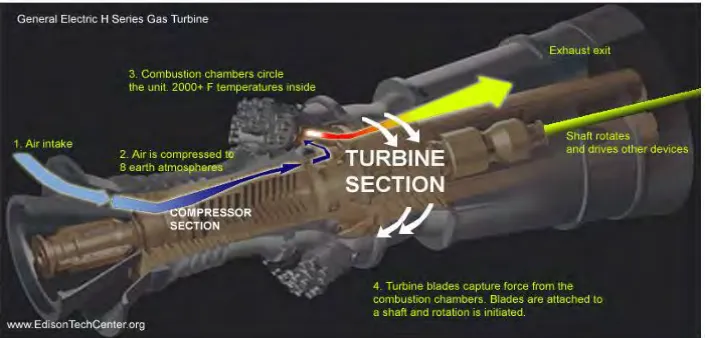
Mostly, gas turbine engine drives for power generation and power aircraft. Figure 2.1 depict
the gas turbine and how the device works. Development of gas turbine can be divided in two
field of technology, namely steam turbine and internal combustion engine. Recent research on
Gas Turbine (Hackert, 2014) has shown the first steam turbine was built by Sir Charles
Parsons and on 1903, gas turbine thesis are established by Dr. Sanford Moss .Year by year,
gas turbine is upgraded and it is accomplished to installed at Oklahoma for electric power
[image:20.612.139.492.522.691.2]generation purpose.
6
The compressor required the power provided by turbine to compress the air in the
engine compressor. Turbine and compressor are the main component in the gas turbine.
Otherwise the combustor, function to be combustion section by burning the large amount of
fuel and air to release the heat. The turbine and compressor have different functional, where
turbine was extracted the work from the flow while compressor was supplied the air at high
pressure. In the other words, the inlet air at ambient pressure is compressed to obtain the air at
high pressure.
2.1.2 Performance of Gas Turbine
Kurz (2005) stated that gas turbine performance is influenced with several ambient
conditions such as ambient temperature, inlet and exhaust pressure losses, fuel, ambient
pressure and relative humidity. The power turbine reduces as more work required to increase
the pressure at higher temperature inlet. With increasing the temperature will lessen the
pressure ratio of the compressor at constant speed. Therefore, component efficiencies in gas
turbine have an effect on changes in the ambient temperature. As well as ambient pressure,
this condition give impact on the power output when the air density is decreased resulting on
the impact of operating the engine at lower ambient pressure. Other than that, it is found that
increasing the tip clearances, changing in airfoil geometry and airfoil surface quality has major
effect on compressor performance. Anoop and Onkar (2014) have shown that there is a change
in specific work output, thermal efficiency and saving of fuel when the compressor inlet
temperature decreased from 318K to 282K which is 10.12, 3.45 and 3.43 percent, respectively.
Arangi, el at. (2015) has analysed that the efficiency and power output has dependency
7
Direction of flow
as increasing of pressure. Low inlet temperature is advantages as it is give the maximum of
efficiency and maximum of power output of gas turbine. Hence, the cooler is provided to
lower the temperature also give the better performance in the gas turbine. Naeim, el.at. (2013)
have been investigated the effect of ambient temperature on the performance of gas turbine
power plant by comparing the ambient temperature for two years. The result shows variation
of efficiency and electric-power output of gas turbines has an impact on electricity production,
fuel consumption and plant incomes.
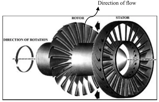
2.2 AXIAL FLOW COMPRESSOR 2.2.1 Introduction of compressor
Axial flow compressor as shown in Figure 2.2, where the air entering the axial
compressor is parallel to the axis of shaft. Pressure ratio and temperature act as the basic
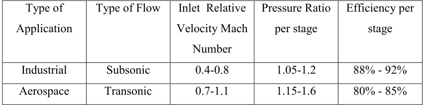
parameter that measure the efficiency of gas turbine. Table 2.1 shows the axial flow
compressor characteristic for two applications, namely industrial and aerospace. Both are used
the compressor for power generation (Boyce, 2011). Axial flow compressor has an advantage
of potential for higher pressure ratio, higher efficiency and larger flow rate possible at given
[image:22.612.184.443.524.690.2]frontal area.
8
Table 2.1 Axial Flow Compressor Characteristic (source: Gas Turbine Engineering Handbook) Type of
Application
Type of Flow Inlet Relative Velocity Mach Number Pressure Ratio per stage Efficiency per stage
Industrial Subsonic 0.4-0.8 1.05-1.2 88% - 92% Aerospace Transonic 0.7-1.1 1.15-1.6 80% - 85%
According to Table 2.1, both type of application for gas turbine have different
characteristic in term of type of flow, Mach number, pressure ratio and efficiency. This is
because they depend on the gas turbine utilization as industrial more to generate electricity,
while aerospace is for power aircraft.
2.2.2 Compressor cascade blades
Many scientists have done their research on cascade wind tunnel and publish their
research. Some are collected as reference for this project. Compressor cascade blade profile
was designed and it is analysed by Pradhapraj, el at. (2016).The model was designed based on
two dimensional flows through a cascade of aerofoil study. Testing cascade model will
provide better result and good operating condition compare to single blade. Difference angle
of blade with various angle of attack of compressor cascade have been done to obtain the
variation of pressure in order to measure the efficiency of compressor cascade. However, the
experimental analysis result was compared to the numerical analysis which carried out using
Computational Fluid Dynamics. Both analysis shows that pressure distribution increased with
increase angle of attack. Thus, efficiency increased. In future, the researches expected
9
Mohsinali and Vimal (2014) has been optimized the number of blades in high pressure
compressor. In designing the compressor, three major design parameter is important including
the number of stages, rotational speed and number of blades. By assumed the rotational speed
6000 to 40000 in range with same boundary condition for 2000 modules, the result shows the
best module with 91 percent of efficiency and 11400 rpm for rotational speed. With help of
Axstream software, number of blade has been selected in rotor and stator. This number of
blades helps the researcher to understanding some parameter such as outlet pressure, enthalpy,
temperature and velocity. Efficiency of compressor is measured in term of energy losses.
Losses occur during the air compression in the compressor, it might be due to friction and flow
separation. Heat loss created by high loaded and higher pressure ratio compressor is the main
losses in this study. Thus, it is shows that increasing the number of blade in rotor would
increase the efficiency as well as power requirement.
Cascade blades are defines as number of blades is assembled in parallel or annular with
similar stagger angle and pitch to one another of blades. The flow is deflected through the
cascade blades due to the loss in stagnation pressure. Research found that the performance of
compressor cascade blade is depending on exit angle with optimum inlet angle and stagnation
pressure loss across on it. Rhoden, el.at. (1942)has been measured the distribution of static
pressure over the central cross section of the middle blade, traverse static pressure and angle
inlet and outlet flow in the plane of the central cross section in experimental. The different
camber angle of axial flow cascade compressor blades with same chord/pitch ratio and same
stagger angle is used in the experiment to obtain the result on effect of Reynolds number on
inlet and outlet air angles, efficiency of blade against Reynolds number and graph of static
pressure over the surface of the middle blade. Incidence flow in cascade has been the