ULTRASONIC CHARACTERIZATION OF SOLID-SOLID BONDS FROM MICROSTRUCTURAL CHANGES
INTRODUCTION
James H. Rose
Ames Laboratory, USDOE Iowa State University Ames, IA 50011
In recent years, new methods of bonding solids have been introduced. These methods (e.g., diffusion bonding and pressure welding) can produce very high quality bonds. In favorable cases the strength of the material in the bond is nearly indistinguishable from that of the host. Similarly, metallographic analysis may indicate almost no microstructural change between the host material and the material in the bonding region. Since these bonds can be of such high quality, they are being used for critical joins. Consequently, an urgent need has arisen for reliable nondestructive inspection methods. This paper is concerned with the use of ultrasound to determine bond quality [1-5].
One obvious way to inspect is to use ultrasound to inspect for disbonds and microcracking [4,5]. However, the bondline can be free of such flaws and the bond may still be quite unacceptable. Such a situation can arise as follows. Bonding depends on the adhesion between atoms. The length scale appropriate for describing such adherence is typically lA in a metal. Anything which interferes with the arrangement of atoms on this length scale has the possibility of degrading the bond. For example, a small amount of an impurity gresent on the surface prior to bonding may lead to a very thin (say 50 A) embrittled region about the bond line. It commonly happens that such regions have high strength. However, their fracture toughness is low due to the embrittlement; the part may fail due to a sharp impact (e.g., dropping it on the floor). Since acoustic wavelengths are typically fractions of millimeters, compared to the lA length scale important for atom-atom bonding, these embrittled bonds will be acoustically transparent. This is obviously a crucial blindspot in the use of ultrasound to directly inspect the bondline. This paper discusses a method that in some cases allows one to avoid this crucial blindspot. It is based on the idea (suggested in Refs. [2 and 3]) that the bonding process may induce microstructural changes in the metal (especially in the near bond region). One then uses ultrasound to characterize these microstructural changes. Finally, one tries to relate the changes in microstructure either directly or
bonding process on that microstructure; and a way of relating of the microstructure to bond quality.
The structure of this paper is as follows. First, we briefly discuss the inference of microstructure from ultrasonic signals. The major
focus is on changes in the ultrasonic attenuation and velocity. Next we discuss as a particular example problem, the inspection of diffusion bonded samples of IN-lOO provided by Pratt and Whitney Aircraft Company. Finally, the paper is concluded with a brief summary.
Ultrasonic Characterization of Microstructural Changes
Bonding, of the type we are discussing, involves the application of high temperatures and substantial pressures. Effects one may expect include: changes in the grain size; changes in the grain morphology; the preferential orientation of grains; phase transitions and the appear-ance of new phases; changes in the relative abundappear-ance of the previously existing phases; the introduction of porosity; changes in the distribution of previously present porosity; the introduction of microcracking; etc. Other relevant possible alterations in the microstructure will no doubt occur to the reader.
The primary tool for ultrasonically inspecting the microstructure are the frequency-dependent velocity shift and attenuation. Crudely, the change in attenuation measures the amount of scattering induced by the microstructural changes, while the velocity shift measures the change in the frequency dependent elastic modulus. Hence, the attenuation is particularly suited to inferring changes in the size of the constituents of the microstructure (e.g., grain enlargement or refinement). The
velocity shift on the other hand, is suited to picking up changes in the relative abundance of the microstructural constituents (e.g., the introduction of new phases, microcracking or porosity). It is also well suited to finding preferential (oriented) grain growth.
However, the attenuation and the velocity shift can be related using causality via the Kramers-Kronig relations. Hence, the attenuation will be sensitive to those microstructural features which cause velocity
shifts and vice-versa. The use of attenuation measurements or velocity shift measurements will depend primarily on the wavelength, the size of the microstructure and the sources of noise.
Many different microstructural changes can occur upon bonding and all of these changes can affect the velocity shift and attenuation. Consequently, one cannot infer the type of change (grain enlargement, porosity, preferential grain growth, etc.) from the ultrasonic measurements alone. However, if the kind of microstructural change is known from
the metallurgy and previous studies, then the extent of the microstructural change may be monitored ultrasonically. For example, the attenuation can be used to monitor grain enlargement.
We will now review the effects of grain size on the ultrasonic attenuation. Let us suppose that we have a single phase material with equiaxed grains. Then the attenuation has been approximated in the Rayleigh limit [6] as
a (1)
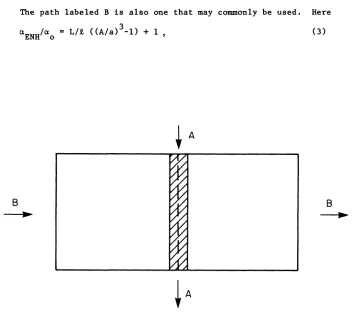
Figure 1 is a schematic representation of a plate which has been formed by pressure welding. The dashed line indicates the bond line while the cross-hatches indicate a region of altered microstructure. This altered region will be referred to as the heat affected zone (HAZ). The arrows indicate two possible experimental set-ups for interrogating the microstructure.
The path marked A is meant to indicate an experiment in which sound transits the plate from top to bottom. The most relevant variable is the size of the transducer to the size of the HAZ. If the transducer is smaller than the HAZ then one finds
Here aHAZ and A denote the attenuation and grain size in the HAZ, while a o and a indicate the same quantities in an undisturbed region far from the bond.
If the transducer is larger than the width of the heat affected zone, one loses almost all leverage on inferring grain enlargement. This arises since the transmitted signal will be dominated by the portion of the beam which propagates outside the HAZ. OIl the other hand, the method will remain useful if there is a significant decrease in the attenuation in the HAZ (due e.g. to grain refinement). In this case the sound propagating in the HAZ dominates the transmission.
The path labeled B is also one that may commonly be used. Here 3
aENH/aO = L/t «A/a) -1)
+
1 , (3)B
~
B
~
[image:3.482.63.416.287.599.2]where aENH denotes the measured total attenuation including the effects of the HAZ, while a o is the attenuation in the absence of the HAZ. Land 1 denote the length of the HAZ and the sample, respectively. This geometry is quite sensitive to grain enhancement. For an example, suppose L=O.lO", 1=1" and A/a=3.0. Then
On the other hand, it is insensitive to grain refinement. Again let L=O.lO", 1=1" and A/a=0.3333, then aENH/ao=0.90.
Example: Bonding of Jet Engine Components
Advanced solid bonding methods are being considered as a means of fixing turbine blades to rotors in the fabrication of jet engine disks. A reliable inspection method is essential for such critical bonds. In order to facilitate the development of such inspection methods, General Electric Aircraft Engine Business Group and Pratt and Whitney Aircraft Company each provided us with a suite of samples. These samples were solicited by and provided to T. A. Gray of the Ames Laboratory. The samples provided are joins in plates. The configuration is nominally similar to the turbine blade-rotor join.
In this section the samples supplied by Pratt and Whitney are used to show how microstructural changes might be used to monitor bond quality. Pratt and Whitney supplied us with four samples: one was a nominal good bond and the other three were deliberately fabricated in such a way that defects were introduced at the joins. Briefly, it was found that the ultrasonic attenuation is dramatically increased in the three "bad" samples, while the attenuation in the "good" sample decreased slightly. These results and their use in bond inspection will now be discussed.
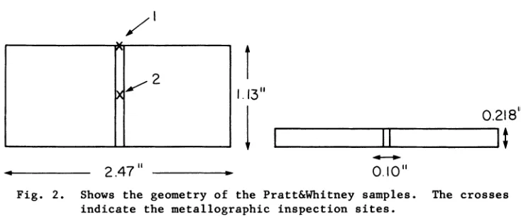
The samples supplied by Pratt and Whitney Aircraft Company are of IN-lOO jet engine material. Their geometry is sketched in Fig. 2. The bounded region indicates the heat affected zone. The crosses indicate places which were examined metallographically by Pratt and Whitney on one side of the plate. The "good" sample was labeled 5 while the "bad" samples were labeled 6, 7, and 8. Table 1 shows the metallographic results for the grain size. As can be seen, the grain structure of samples 5 and 6 were unaffected at the inspection sites, while 7 and 8 show evidence of substan-tial grain enlargement. The appearance of enlarged grains is a character-istic problem (blown grains) which can appear when the bonding temperature is too high.
Table 1- Shows grain sizes supplied by Pratt and Whitney for one side of samples 5, 6, 7, and 8.
Sample Edge Position Central Position
5 ASTM 12 (6pm) ASTM 12 (6 pm)
6 ASTM 12 (6pm) ASTM 12 (6 pm)
7 ASTM 12 (6pm) ASTM 6-8 (22-44pm)
As discussed in the last section, the appearance of grain enlargement leads one to expect a substantial enhantement in the ultrasonic attenua-tion. To test this the samples were examined using a 50 MHz focussed immersion probe. The experimental geometry is shown schematically in Fig. 3. The probe was focussed slightly in front of the back surface. The strength of the back surface reflection was measured in the heat affected zone, and then "off-the-bond" in a region far from the HAZ.
".-2
~r
1.13"0.218"
I
.---'T'TII---.I
t
•
2.47"
-
0.10"
Fig. 2. Shows the geometry of the Pratt&Whitney samples. The crosses indicate the metallographic inspection sites.
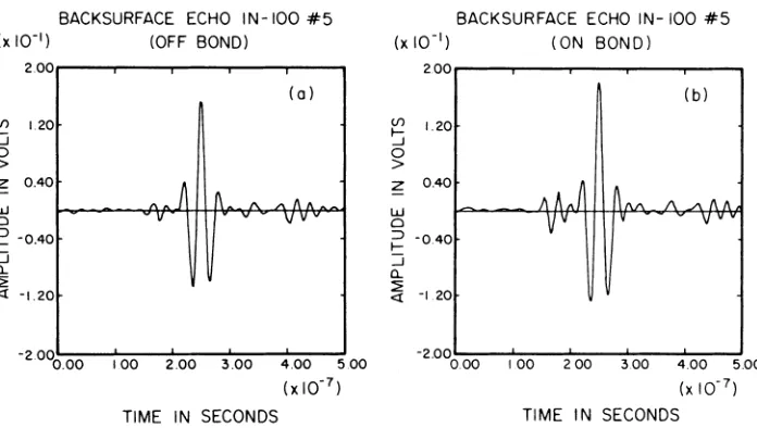
The results for the "good" sample (1;5) is shown in Figs. 4A and
4B. The back surface echo is actually slightly larger in the heat affected zone ("on bond") than "off the bond". This 15% increase in the signal is significant and reproducible. Figures 5A and B show a typical result for one of the bad samples. The signal in the "on bond" position is less by roughly a factor of ten than in the "off bond" position. Similar results were obtained for the other "bad" samples (#6 and #8). In summary, there was a very substantial increase in the ultrasonic attenuation
of the "bad" samples 6, 7, and 8 for a 50 MHz probe. However, the attenuation was actually decreased slightly for the good sample.
DISCUSSION
[image:5.482.53.420.182.336.2]ON BOND OFF BOND
Fig. 3. Shows the geometry for the measurements made on the Pratt&Whitney samples.
BACKSURFACE ECHO IN-IOO #5
(x 10-1) (OFF BOND)
2.00...--...,....--,...-...,....--,...--.
en 1.20 ~
o
>
Z OAO w
o
;:: -0.40
:::i
a.
~
<t -1.20
(0)
v V v
-2000 .00 1.00 2.00 3.00 4.00 5.00
(xI0-7 )
TIME IN SECONDS
BACKSURFACE ECHO IN- 100 #5
(x 10-1) (ON BOND)
2.00,.---r--...--...,....--...---.
en 1.20 ~ o
>
~ 0.40
W
o ;:: -OAO :::i
a.
~ -120
(b)
fi
IV\ /\.A 1\ 1\v V v v
-2.00~:--~~---::~-~~---::~---::-:.'
0.00 I 00 200 300 4.00 5.00
(x 10-7 )
TIME IN SECONDS
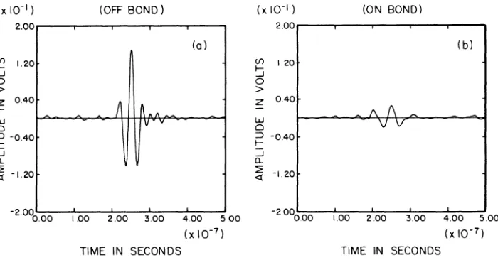
[image:6.482.138.356.92.243.2] [image:6.482.72.420.323.520.2]BACKSURFACE ECHO IN-IOO #7
(x 10-1) (OFF BOND)
2.00..---r----.---... --T"""---,
(f) 1.20 ~
o
>
Z 0.40
W
o
i=
-0.40:::i
a..
~ -1.20
(a)
v
-2.000 .00 1.00 2.00 3.00 4.00 500
(x 10-7 )
TIME IN SECONDS
BACKSURFACE ECHO IN-IOO #7
(x 10-1 ) (ON BOND)
(f) ~ 0 > Z W 0 :J f-:::i a.. ~ «
2.00,..---r----.---... - - . - - - - ,
1.20 0.40 -0.40 -1.20 -2.000 .00 (b)
1\./\
vv
1.00 2.00 3.00 4.00 5.00
(x 10-7 )
TIME IN SECONDS
Fig. 5. Shows the backsurface echo strength for a "bad" sample (#7). Position A is "off the bond", while position B is "on the bond".
and etched on the flat (opposite the one examined by Pratt and Whitney) large grains were found in the HAZ (50~m or 8 times larger than the host material). This enlargement of the grain structure in sample 6 easily accounts for initially unexpected high attenuation.
Thus the large increase in the attenuation of the three "bad" samples can all be accounted for by the substantial grain enlargement. Presumably the excessive grain growth occurred due to the deliberately high bonding temperature. On the other hand, the nominally "good" sample actually showed a decrease in attenuation.
For the suite of samples studied, the attenuation provides a simple sharp signal which distinguishes the "good" from the "bad" samples. Further, the attenuation decrease for the "good" sample indicates that we have sufficient sensitivity to detect good bonds as well as bad ones. Thus the attenuation may be sensitive to variations in the quality of good bonds. Further study of this possibility is needed.
The results of this paper suggest two possible immediate applications. First, the attenuation might be used as a process control monitor for bond quality. A rise in attenuation during bonding might indicate excess grain growth and indirectly inappropriate bonding parameters. Second, attenuation measurements when combined with the direct inspection of the bond-line [5], suggests a possible way of examining diffusion bonds in IN-lOO for integrity.
[image:7.482.68.418.43.226.2]most useful when combined with a detailed knowledge of the parts metallugy and the details of the bonding process.
ACKNOWLEDGEMENT
This work was sponsored by the Center for Advanced Nondestructive Evaluation, operated by the Ames Laboratory, USDOE, for the Air Force Wright Aeronautical Laboratories/Materials Laboratory under Contract No. W-7405-ENG-82 with Iowa State University. I thank Pratt and Whitney Aircraft Company and G.E. AEBG for the samples. Also, I thank Drs. T. A. Gray and F. Margetan for making the measurements of the back surface echo strength and D.
o.
Thompson and R. B. Thompson for suggestingthe problem. REFERENCES·
1. B. H. Hosten, L. A. Ahlberg, B. R. Tittmann, and J. Spingarn, "Ultrasonic Characterization of Diffusion Bonds", in Review of Progress in
Quantitative NDE, D. O. Thompson and D. E. Chimenti, Eds., (Plenum Press, NY, 1987), 6B, 1701).
2. D. K. Rehbein, D. ~ Hsu, R. B. Thompson and T. A. Jones, "Ultrasonic NDE of Tubing Pinch Welds", ibid, p. 1737.
3. G. H. Thomas, J. R. Spingarn and S. E. Benson, "Ultrasonic Evaluation and Imaging of Tube Closure Welds", ibid, p. 1747.
4. D. D. Palmer, D. K. Rehbein, J. F. Smith, and O. Buck, "NDE Charac-terization of Metallic Interfaces", ibid, p. 1755.
5. T. A. Gray, R. B. Thompson and F. J. Margetan, "Ultrasonic NDE of Integrally Bladed Rotors", ibid, p. 1763.