International Journal of Innovative Technology and Exploring Engineering (IJITEE) ISSN: 2278-3075, Volume-8 Issue-8, June 2019
Abstract: This paper introduces Raised Cosine Filter (RCF) based Adaptive Cyclic Prefix (ACP) method with fixed Roll-off factor that efficiently reduces phase offset of a conventional BWA system. RCFACP delivers a fair Quality of Service (QoS) to the end users within a given BWA network without compromising with either Raw Data Rate (RDR) or Spectral Efficiency. Further reduction in phase offset has been achieved by modifying the RCF, having Adaptive Roll-off Factor (ARF). A detailed design process followed by extensive mathematical derivations establishes ACPARF algorithm within a standard BWA Transceiver (TxRx). The simulation results reveal that ACPARF registers an impressive 63% better error correction in contrast to RCFACP. Additionally, ACPARF also minimizes ISI to significant proportions, under severely poor channel condition. Results also confirm that ACPARF works far better than that of the existing ACP algorithm by delivering a 80% enhanced error rectification for higher order modulation for generic BWA network.
Index Terms: Cyclic Prefix, Inter Symbol Interference, Raised Cosine Filter, Raw Data Rate, Roll off factor, LTE
I. INTRODUCTION
The revolution surrounding wireless communication has been phenomenal in the last decade. The seemingly impossible option of instantaneous connectivity with data rates upto several gigabit has been promised by LTE [1] and LTE-A. This in fact has lead to the foundation of further research towards 4G and beyond. The primary objective was set as to provide dramatic increase in data connectivity with uninterrupted service for user with mobility. In light of this both IEEE 802.16e and IEEE 802.16m [2] were introduced having user mobility. Theoretically, for 5G scenarios IMT-2020 proposes a peak data rate of 10 and 20 Gbps for uplink and downlink respective scenarios [2]. However, multipath fading and propagational hazards plays havoc for severe reduction in data rate. So a significant effort should be made in order to achieve a reasonably good Quality of Service (QoS) keeping the desired objectives intact.
It is a sensible option to include unique modification to individual block structures within physical layer to improve QoS. Following this, both WiMAX and LTE supports Adaptive Modulation and Coding (AMC) technique to attain maximum Spectral Efficiency (SE) [3]. Even “cognitive” propagation of signals is implemented to achieve best possible data throughput [4]. The latest trend include Deep Learning (DL) [5] driven physical layer communication that dictates Channel State Information (CSI) [6], Sparse and Temporal correlation of CSI [7] with Comprehensive
Revised Manuscript Received on June 07, 2019.
Budhaditya Bhattacharyya, Department of Communication Engineering, SENSE, VIT , Vellore, India.
.
Sensing (CS). The betterment in channel coding using data driven channel coding has also been introduced with Recurrent Neural Network (RNN) decoders [8]. On a similar trend, the multiple accesses like OFDMA with Cyclic Prefix (CP) [9] also demand some key modifications. It suffers drastically from synchronization errors [10], Peak to Average Power Ratio (PAPR) [11], Inter Carrier Interference (ICI) [12] and is very much sensitive to fast time variation of wireless channels. The modifications in the existing models will be such that it reduces Error Vector Magnitude (EVM) [13] and Relative Constellation Error (RCE) [14] that characterizes such errors. . Innovative and unique solutions to counter time and frequency synchronicity with lower PAPR and ICI mitigation have already been devised [15-17]. Even Adaptive Cyclic Prefix (ACP) based ISI removal has been proposed which in fact works well in WiMAX scenarios [18-20]. This strategy [18] helps gaining a significant leverage over Raw Data Rate (RDR) with a control over ISI. Following this success, a Raised Cosine Filter (RCF) [19] based LTE Transceiver (TxRx) has been proposed in this paper. This revision is done keeping in mind that the radio amplifier within the TxRx shows a non-linear behavior which amplifies transmitted signals that results in Spectral Broadening (SB) [21] causing ISI [22]. Pulse Shaping Technique (PST) is a feasible solution as have already been established by [23-26]. One of the solutions [23] were to transmit data over PST based band limited channel to eliminate ISI, while a significant reduction of PAPR and ICI can be associated with the work presented in [24]. Even, for Wideband CDMA and Ultra Wide Band (UWB) PST has successfully excelled in noteworthy improvement in SE [25-26]. However, the comprehensive performance analysis on the effect of PST over an OFDMA based LTE network has not yet been reported. Here lies the significance of this paper, as it primarily deals with the effectiveness of PST on a typical WiMAX scenario under the application of adaptive roll off Raised Cosine Filter (RCF) based ACP strategy. In general, the choice of RCF over Nyquist and Gaussian filtering has well been established in [27]. Thus [27] justifies the inclusion of RCF within the generic BWA TxRx that typically supports 7 different modulation and coding standards. By generic it is meant that the designed TxRx will be equipped to be working robustly for both WiMAX and LTE. The performance is adjudicated in the form of Average Error Result (AER) observed for all possible modulation and coding schemes as per WiMAX and LTE standard. Roll off Factor (β) governs the roll off between consecutive symbols filtered by RCF.
Scalable Cyclic Prefix Based Adaptive Roll-off
Factor for Phase Offset Reduction in LTE
In effect a drastic reduction in consecutive symbol overlapping is observed, causing minimum ISI. Hence by dynamic selection of β, a direct control over ISI can be adjudicated. Moreover, it is intuitive that if ACP algorithm is used in conjunction with novel “Adaptive Roll off Factor (ARF)” method, a far better ISI removal can be assured for any given system. So in this paper, a unique ACPARF algorithm has been proposed where with every change in channel SNR both CP and β changes adaptively. This makes ACPARF algorithm to have a control over ISI; whereas maintaining a substantially good RDR and SE. Thus the most important and significant findings of this paper will include:
1) Analysis of the effect of RCF on the performance on a Generic BWA TxRx.
2) To justify the significant contribution of ACPARF algorithm in comparison with conventional phase offset reduction techniques for a given WiMAX / LTE Network under poor channel condition.
The other sections of the paper include theoretical background in Section II. The design methodology for RCFACP and ACPARF are described in Section III. The proposed ACPARF algorithm has been explained in full detail in Section IV, while the exhaustive simulation results have been discussed in Section V. Finally, Section VI concludes the paper.
II. BACKGROUND
The frame work for implementing the TxRx is based on the generic assumption of any OFDM based transmission schemes as depicted in [27]. Each OFDM block contains N subcarriers, Xn {n=0, 1, 2, ..., N-1} which is encoded and
modulated prior to transmission over wireless channels. The time domain representation given in (1) does not includes CP. [9],
N 1
0 n
T t 0 t
n f 2 j exp n X N 1 t x
(1) The adjacent symbol interference can now be limited by including CP (Tg) that by principle should be kept more than
the maximum delay spread of the channel. Hence, the reflected, echoed and delayed multipath disperses within Tg.
It should be fair to take into cognizance that application of longer CP has its adverse effect on reduced SE, RDR and increasing overhead.
A. Adaptive CP in BWA Scenario
As RCF plays key role in band limiting the OFDM symbol [9], accordingly (2) indicates the modified scenario where the RCF and CP are both fitted with each other.
1 2 N
1 2 N n
s kT t u T
n c f 2 j exp n X s
kT t w N 1 t x
(2) Where, fc = center frequency of the occupied frequency
spectrum, Tu = Useful OFDM Symbol time, ∆f = 1/Tu =
Frequency spacing between adjacent subcarriers, Ts = Time
between two consecutive OFDM Symbols and w(t) = Window Function. The primary assumptions being
(i) section of subcarriers ( Nused <= N) are useful data
carriers, given N point IFFT is used [9][21] and (ii) As pointed out in [26], fc should be null. Primarily (i) has been
established keeping in mind that the subcarriers close to Nyquist Frequency (fs/2) will be attenuated by the filters
required for the Analog to Digital Conversion (ADC) at Tx
and Digital to Analog Conversion (DAC) at the Rx. In this
paper similar conditions have been considered. i.e. Nused= N,
for N= 128, 256, 512, 1024 and 2048. On a similar note for Nused= 256 and 1024, ND must be 192 and 768 respectively.
So Nused must be equal to N instead of any arbitrary value.
Hence it has been assumed that no subcarriers get attenuated at fs/2. Accordingly (ii) makes each OFDM symbols to be
spaced at n∆f {n=1, 2,.., N-1} apart, while maintaining the orthogonality. Hence (2) can be rewritten as (3),
1
0
2 exp
N
n
s n
k
S X j n f t kT kT
t w t
x
(3) Now to form the OFDM symbol, Tg is divided into two
equal halves of Tg /2 proportions. Thereafter, one half (Tg /2)
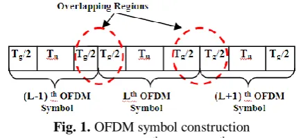
[image:2.595.322.541.323.423.2]is prefixed as conventional CP. The remaining half remains as postfixed CP like shown in Fig. 1.
Fig. 1. OFDM symbol construction
Naturally, a Tg/2 portion of Lth and (L-1)th OFDM symbol
will overlap with same portion of L+1th and Lth OFDM symbol respectively as clearly depicted in Fig. 1. It is in fact apparent from Fig. 1 that these two overlapping regions will make the overall OFDM symbol duration as 2Tg.
Consequently, the RCF specification and roll off regions are also governed following this specific orientation.
B. Windowing Techniques in BWA Scenario
A raised cosine window with unity gain is proposed within the time interval [2Tg, Ts] with roll off occurring at 2Tg and
Ts. The implementation is demonstrated with Fig. 2. It is to
be noted that by careful selection of β, length of the window is selected, which in turn decides the extent of out-band radiation. Keeping design overhead to be minimum, β has been related with CP within the overlapping range of 2Tg.
Hence β has been expressed as (4) [25] depicting a direct relationship between CP and β. The effect of CP on the window technique has been clearly established in (5), by the incorporation of Tg on the window function as described in
[26]. Accordingly, these filter specifications along with the novel OFDM symbol structure constitute the basis of a sustainable RDR under conventional WiMAX scenario. As (Bs), code rate (Cd), ND and overall symbol duration (Tsymbol)
form the basis of RDR [18],[28] they can be represented as (6), Where ND is based on LTE standard for corresponding
International Journal of Innovative Technology and Exploring Engineering (IJITEE) ISSN: 2278-3075, Volume-8 Issue-8, June 2019
Fig. 2 Guard band based Window Specifications
g T 2 s T s T g T 2 (4) g T 2 s T i s T s T s T t cos 1 2 1 s T i g T 2 1 Tg 2 i 0 s T i 1 cos 1 2 1 ) i ( w (5)
The overall expression that relates RDR in terms of β and CP as given by (7), where Tg can be defined as in standard [18]
by (8). While, Pf is the oversampling ratio standardized as per
generic BWA standards [1] and is tabulated in Table I [18]. Equating (8) on (7) we get (9), the final expression to evaluate RDR. Ts ) d C s B D N (
RDR
(6)
2Tg
) d C s B D N (
RDR
(7)
8000 8000
BW P N CP T f FFT g (8) FFT N CP 2 8000 8000 BW f P ) d C s B sub N ( RDR (9) Thus (9) gives an optimal solution to obtain a high data throughput at a significant SE, with control over CP and roll off factor. In light of the above discussion, it is indeed a necessity to discuss about the maximum power loss associated with addition of CP on OFDMA system. CP acts as an extension of the transmitted signal in the time domain in order to overcome ISI in a multipath radio channel. This extension is dynamic in nature, as it involves variation of CP length depending upon system requirements. However, addition of redundant data as CP comes at a cost of drop in overall energy of the system. Accordingly, to get an account of this loss in energy, transmitted Power Spectral density (PSD) is being considered a quantitative measuring tool. Conventionally, PSD shows the strength of variation of energy as a function of frequency that can be expressed as (10) [19], [29-31]. Likewise (11) gives the PSD expression of a typical OFDM signal along with the variations in energy due
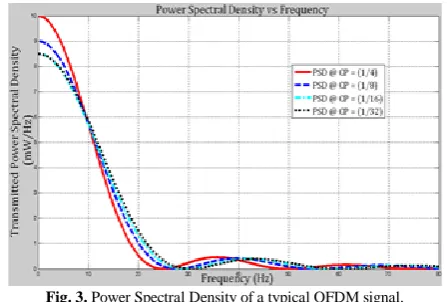
[image:3.595.319.543.106.257.2]to the effect of CP. Following this, Fig. 3 clearly depicts the loss of energy for a given CP. As CP = 1/32 provides the minimum guard band to an OFDM signal, it provides less power loss.
Fig. 3. Power Spectral Density of a typical OFDM signal. This is prominent from the PSD graph for CP= 1/32 in Fig. 3, where a loss of 8.23 mW/Hz has been recorded. On the contrary, at CP= ¼ for both WiMAX and LTE , OFDM suffers heavy loss in energy registering more than 10 mW/Hz. Thus power variation of a transmitted OFDM signal is greatly controlled by the application of CP and hence must be judiciously altered depending upon specific requirements.
2* * 2 * S S S OFDM T f T f Sin T A f (10)
f g f f g f Sin f g A f or T T f T T f Sin T T T A f OFDM g B g B g b OFDM 1 1 1 , * * 2 * 2 2 * (11)III. SYSTEMDESIGN A. Raised Cosine based design methodology
Use The general implementation of a BWA TxRx has been
discussed in this section following [27]. In general, Raised Cosine Pulses (RCP) are modified Sinc pulses, with an adjustable BW (WNq) and can be represented as (12) [21]
where WNq is Nyquist BW. To reduce power loss, BW
utilized (W0) by the filter must be as close to WNq. Thus β
should control W0 as indicative from (13).
2Ts 1 Nq
W
(12)
[image:3.595.50.290.378.570.2]Following (4), the calculated values of β for various standard CPs (1/4, 1/8, 1/16 and 1/32) [1] are calculated as 0.4, 0.22, 0.11 and 0.06 respectively.
Fig.4. Conventional Raised Cosine Filter and Customised Pulse Shaping Filter based WiMAX Transceiver as implemented in Simulink.signal
It should be mentioned that for LTE scenario, CP = ¼ is only considered. This is because although LTE specifies both Normal (1/4) and Extended (9/64) CPs, the normal cyclic prefix is intended to be sufficient for the majority of scenarios. Even, the BWA network needs to bear 18% more overhead (Ts / FFT) for Extended CP, in comparison to 7 % for NCP. In this proposed method, a more emphasis is given on the role of RCF on BWA network rather than experimenting with ECP. Equation (4) reveals that β can only achieve a theoretical maximum value of 0.4. This can also be verified from [23] that the typical value of β in wireless communication varies between 0.2 and 0.4. So keeping these assumptions on RCF, the value of β is included within RCF block, both at Tx and Rx of the TxRx [18]
architecture as shown in Fig. 4.
In this paper an exhaustive simulation is done as explained in [32] with the only difference being, half of the guard carriers are prefixed. As for example, typically for CP =¼, 64 guard carriers within a total of 256 subcarriers gets appended as CP. Also instead of fixed duration of CP, the much established ACP strategy [18-20] has been taken into consideration for performance analysis. However, in our proposal out of these 64 guard subcarriers, 32 are prefixed and 32 remains as post-fixed guard carriers. Thus, no additional design overhead is required. To include RCF block within the LTE model, “Raised Cosine Transmit Filter (RCTF)”, shown in Figure. 4, has been considered that upsamples and filters the input time domain signal using a normal raised cosine FIR filter or a square root raised cosine FIR filter [33]. Accordingly, specific instantiations of different parameters within RCTF is essentially required to make it active for operation. These include specification of Group Delay (GD), β and Upsampling Factor (UF). Both GD and UF are important parameters in calculating the length of the filter impulse response [33]. As per simulation convention for WiMAX, CP=1/8 is taken as guard interval
[1]. Hence initially β is considered as 0.22 with keeping GD and UF to their default value of 4 and 8.
The “Raised Cosine Receive Filter (RCRF)” filter is specified like that of RCTF to avoid any undue mismatch between Tx and Rx filter. The interconnection of RCTF and RCRF within TxRx has been clearly depicted in Fig. 4. In this
paper, following the same design methodology as described in [32], VSA has been interfaced to measure EVM and RCE. As considered by recent literatures [15], [34-35] both of these attributes act as a direct identifier to ISI.
B. Design Methodology for Adaptive Roll off Factor
Because The design methodology for ACP as already mentioned in [32], suggests declaring ‘index option’ of ‘Selector Block’ of Simulink with a variable ‘CPSel’. For each
iteration, corresponding CPSel is being assigned with the
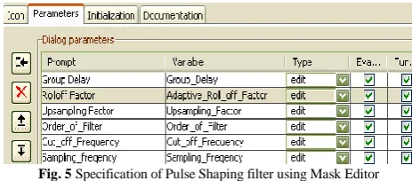
exact CP value preferred under that specific channel condition, influencing the output results. Same process is adopted while implementing Adaptive Roll off Factor (ARF) algorithm with certain degree of complexity with β ranging between 0 and 1. Neither RCTF nor RCRF have the provision to be initialized by a variable like ACP. Hence, new innovative design strategy is adopted. Let a workspace variable ‘Adaptive_Roll_off_Factor’, defines an array of β values [0.4, 0.22, 0.11 and 0.06] for each assigned SNR dependent CP. Hence now effect of both ACP and ARF must reflect within the BWA system. In this paper, using the feature “Mask Editor” in Simulink, specific features like icon, parameters for Pulse shaping have been implemented as shown in Fig. 5. The customized block takes the assistance of inbuilt MATLAB function ‘FIRRCOS (η, Fc , β,
Fs, 'Rolloff', DESIGNTYPE)’, where η, Fc , β, Fs are the
Order, Cut off Frequency, Roll off Factor and Sampling Frequency of the RCF filter respectively.
Direction of Signal propagation through TxRx @ RCFACP Direction of Signal propagation through TxRx @ ACPARF
Interconnection for Conventional Raised Cosine Filter Block of Simulink
International Journal of Innovative Technology and Exploring Engineering (IJITEE) ISSN: 2278-3075, Volume-8 Issue-8, June 2019
Function FIRRCOS returns a ηth order low pass linear phase FIR filter with a raised cosine transition band. Although primary focus is given on the dynamic variation of β, a close inspection of η, Fc and Fs must
Fig. 5 Specification of Pulse Shaping filter using Mask Editor also be taken into account. Following the detailed description of implementation of RCF as given in [36], similar approach has been conceived while designing ARF. The first consideration in FIR filter design is the sample rate (Fs). Following the design standard as specified in [19], Fs can be defined as
8000
8000 BW f P s
F
(14) For BW = 10 MHz (multiple of 2), Pf as 57/50 Fs can be
calculated as 8 kHz [19]. Now as per design constrain Fc must
lie between 0 < Fc <= Fs /2, where Fs/2 denotes Nyquist
Frequency. Likewise, in our scenario, Fc is considered as
Fs/4. The specification of η is purely based on two key
attributes such as i) The amount of Upsampling desired and ii) Length of time that the filter’s response is expected to span. Theoretically, more Upsampling yields a more accurate frequency response characteristic. Hence one can select oversample by three, four or more [36]. The second factor is typically a designer’s choice as to how many number of bits (or symbol) should the filter response occupy. Based on these predefined assumptions, two variables ‘Upsampling_Factor (U)’ and ‘Length_of_impulse_response (L)’ have been defined in MATLAB with having specification as 8 and 5 respectively. Hence η, the order of the filter, used to in our scenario can be calculated as 40 (η = U*L) as described in [36]. So the complete window panel for the desired RCF can be visualized as in Fig. 5. This is unique to the fact that the parameters are all customized and programmable as per designer specification. The difference between the standard RCTF and the customized
Fig. 6Standard specification of Raised Cosine Transmit Filter
Fig. 7 Typical screenshot of Pulse shaping Filter Window Panel with ARF.
Pulse Shaping Filter Block can be visualized clearly by comparing both Fig. 6 and Fig. 7. Observation reveals that instead of a numeric number for β as in Fig. 6, a variable Adaptive_Roll_off_Factor’ has been assigned that holds corresponding β for specific ACP, under a given channel condition.
IV. ACPASSISTEDARFALOGORITHM
Both the proposed RCFACP method and ACPARF algorithm are primarily based on already established ACP algorithm. Specifically, the inclusion of ARF dictates major changes in the existing ACP algorithm. β has been considered to be constant for each varying CP value till now, in order to observe the contribution of filter roll off on a typical BWA TxRx. Thus for RCFACP method, there is
hardly any significant change that is brought about within ACP algorithm. However, this method has a particular practical constrain. For each CP there exist a single β as already given by (4). So whenever a particular CP (say CP = 1/4) is chosen β must be selected (β =0.4) accordingly. However, as per the theory of ACP algorithm, with variation of channel SNR, dynamic switching is observed among standard CP duration. Hence subsequently, dynamic change must be brought on β as well. As for example, when CP=1/4, β must be 0.4. Now while CP changes to 1/32, β must register a value of 0.06 instead of 0.4. It also triggers a concept of having dynamic β that will change with every change in CP.
So on one hand ACP will reduce the phase error magnitude, whereas on the other hand an adaptive β will reassure QoS by improving ISI caused to the system. Accordingly, this forms the basis of the proposed ACPARF algorithm as discussed in this section. Since CP and β are directly related by (4), there exist a one-to-one mapping between Error offset, Channel SNR, CP and β as tabulated in Table I. In this regard it should be mentioned that the range of AER and channel SNR (SNRCh) refers to the existing ACP
strategy as described in [18]. ACPARF is primarily based on SNRCh and varying β instead of only SNRCh as in ACP.
[image:5.595.320.545.50.165.2] [image:5.595.56.288.105.207.2] [image:5.595.59.284.604.714.2]CPs are ideally selected on the basis of decreasing data redundancy (CP=1/4 ->1/8 -> 1/16 ->1/32) to alleviate error offset at poor SNRCh. However, a close scrutiny reveals that
especially when AER is 6dB or higher, with very low SNRCh,
the decreasing order of CP is ideal for the scenario. For a higher SNRCh or better AER, changes must be made in the
[image:6.595.316.552.49.274.2]order of selecting CP accordingly. This primarily necessitate the application of “Dynamic CP Combinations” as per given channel condition. While designing ACPARF, four different combination of CPs are selected based on left cyclic shift of CPs as given in (15). Hence it is intuitive that β too will take corresponding values following (15) and Table I. The complete categorization is largely based upon the range of AER, which has been depicted using the flowchart in Fig. 8. Moreover, it is intuitive from the results in Section V that these specific arrangements of CP and β allow a significant drop in error offset, while maintaining a fair data rate.
Table I Specification of AER, Channel SNR, CP and Roll off Factor
1
Is l<=20? 4
is j<=length of Cyclic Prefix? No Yes 3 No Stop Yes 2 2
CP1= 1/32, CP2 =¼ , CP3 = 1/8, CP4 = 1/16 β1= 0.06,β2 = 0.4, β3 = 0.22, β4 = 0.11
Is 2 < = AER < 4?
Is 4 < = AER <6?
Is 6 < =AER< inf? No
Display “AER out of
scope” No No Is 0<=AER <2? 3 Stop F Select a specific modulation scheme
& code rate and Vary BE, CE and MS to achieve above specified modulation scheme
& Code rate
CP = Cyclic_Prefix
SNRCh= 1dB
Have the above steps being correctly implemented? 1
VSA generates output results
Select EVM_Analysis and
RCE_Analysis from VSA
l=1
3
cSNR =cSNR+1
j=1 Yes Start
Avg_Error_Result(AER) = (EVM_Analysis +RCE_Analysis)/2
No E E2 E1 E3 F F F F
Select β in the order β1 -β2 - β3 - β4
Select β in the order β3 - β4 - β1 - β2 Select β in the order
β4 - β1- β2 - β3
Select β in the order β2 - β3 - β4 - β1
Yes Yes
Yes
Yes
Fig.8 Flow chart for the implementation of ACPARF Algorithm
Is 1<=SNRCh < 5?
Is 5<=SNRCh < 10?
Is 10<=SNRCh < 15?
Is 15<=SNRCh < 20?
E CP1 CP2 CP3 CP4 Yes Stop Yes Yes Yes Yes Is 1<=SNRCh < 5?
Is 5<=SNRCh < 10?
Is 10<=SNRCh < 15?
Is 15<=SNRCh < 20?
E1 CP4 CP1 CP2 CP3 Stop Yes Yes Yes Is 1<=SNRCh < 5?
Is 5<=SNRCh < 10?
Is 10<=SNRCh < 15?
Is 15<=SNRCh < 20?
E2 CP3 CP4 CP1 CP2 Yes Stop Yes Yes Yes Yes Is 1<=SNRCh < 5?
Is 5<=SNRCh < 10?
Is 10<=SNRCh < 15?
Is 15<=SNRCh < 20?
E3 CP2 CP3 CP4 CP1 Yes Stop Yes Yes
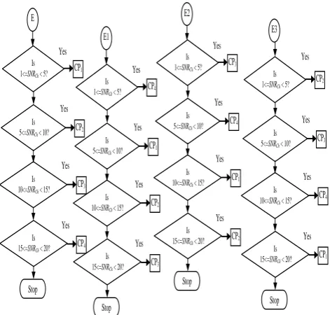
Fig. 9 Flowchart depicting different combination of CP selection for ACPARF Algorithm
The complete ACPARF algorithm has been clearly explained using the flow chart depicted by Fig. 8. The different combinations of β and CPs, categorically form
1/32] 1/16, 1/8, [1/4, = Prefix_4 ic Array_Cycl 1/4] 1/32, 1/16, [1/8, = Prefix_3 ic Array_Cycl 1/8] 1/4, 1/32, [1/16, = Prefix_2 ic Array_Cycl 1/16] 1/8, 1/4, [1/32, = Prefix_1 ic Array_Cycl (15) 0.06] 0.11, 0.22, [0.4, = rray_4 Roll_Off_A 0.4] 0.06, 0.11, [0.22, = rray_3 Roll_Off_A 0.22] 0.4, 0.06, [0.11, = rray_2 Roll_Off_A 0.11] 0.22, 0.4, [0.06, = rray_1 Roll_Off_A (16) another flowchart as given in Fig. 9. Each range of AER like E, E1, E2, and E3 dictates the selection of specific order of β. Accordingly SNRCh and CPs merge in different combinations
as given in Fig. 9. Following the flow chart, the working principle of ACPARF algorithm can be summarized as follows:
[1]After selection of particular modulation schemes and code rate, the WiMAX TxRx is simulated for the lowest
possible SNRCh (SNRCh=1dB).
[2]SNRCh is gradually increased to a maximum of 20 dB.
[3]AER is calculated from the obtained EVM and RCE results obtained from VSA 89600 under that particular channel condition.
[4]Based on the predefined range of AER, as given in Table I, extent of error offset is categorized.
[5]Both AER and corresponding SNRCh are checked based
on Table I.
[6] For each selected ranges for AER and SNRCh, select
specific “Array_Cyclic_Prefix” and corresponding “Roll_off_Array” following (15) and (16) respectively.
Accordingly, adapt specific β (β1, β2, β3, β4) based on
corresponding order of CP (CP1, CP2, CP3, CP4) as given in
the flowchart of Fig. 9.
AER Channel SNR CP β
0<=AER<2
1<= SNRCh< 5 1/32 0.06
5<= SNRCh< 10 1/4 0.4
10<= SNRCh< 15 1/8 0.22
15<= SNRCh< 20 1/16 0.11
2<=AER<4
1<= SNRCh< 5 1/16 0.11
5<= SNRCh< 10 1/32 0.06 10<= SNRCh< 15 ¼ 0.4 15<= SNRCh< 20 1/8 0.22
4<=AER<6
1<= SNRCh< 5 1/8 0.22 5<= SNRCh< 10 1/16 0.11 10<= SNRCh< 15 1/32 0.06 15<= SNRCh< 20 1/4 0.4
6<=AER<inf
[image:6.595.59.282.286.760.2]International Journal of Innovative Technology and Exploring Engineering (IJITEE) ISSN: 2278-3075, Volume-8 Issue-8, June 2019
V. RESULTS
A. Phase Error offset using Fixed β based RCFACP algorithm
In this part, thesimulation results primarily comprise of effective phase error correction by RCFACP. The general simulation parameters include 256 subcarriers, with selected modulation and coding schemes like QPSK (3/4), 16-QAM (3/4) and 64-QAM (3/4). 1dB to 20 dB is selected as the channel SNR. All these specifications have been considered in order to make a direct comparative analysis between RCFACP and ACP since the later uses the same simulation parameters for a similar multipath Rayleigh Fading environment [18]. As depicted in Fig. 10, when β = 0.22, a massive drop (0.987 dB) in AER (epitomized in the form of phase error offset) can be observed at severely poor channel SNR (4 dB). Also a maximum error offset of 11.43 dB is obtained for CP =1/32 which is logical. Even it has been verified that for 16-QAM (3/4) and 64-QAM (3/4), RCFACP works well. As shown in Fig. 11 for 16-QAM (3/4) modulation, at SNRCh = 4 dB, compared to FCP (=1/8), error
[image:7.595.311.542.45.462.2]performance improves by almost 80% for RCFACP. This considerable improvement is observed throughout the varying channel SNR condition.
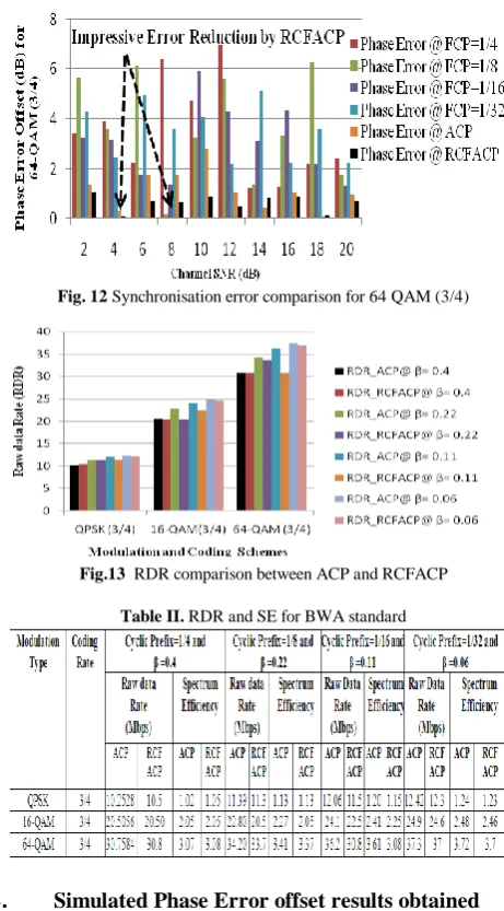
[image:7.595.57.286.357.464.2]Fig. 10 Synchronisation error comparison for QPSK (3/4) modulation A significant 22% improvement is observed when comparison is made between ACP and RCFACP for similar condition at 6dB. While 2.2 dB phase error is recorded for ACP, RCFFACP registers 1.7 dB. A similar trend of declining ISI is observed for 64-QAM (3/4) modulation as well which is depicted in Fig. 12. Analysis also suggests that about 34% error improvement can be obtained when RCFACP is used instead of ACP at poor channel SNR (= 4dB) for 64-QAM (3/4). Thus RCFACP proves its immense importance to be judiciously used under severely deteriorating fading channels. The significance of RCFACP strategy is even enhanced as it does not sacrifice RDR and SE as tabulated in Table II and demonstrated in Fig. 13.
Fig. 11 Synchronisation error comparison for 16 QAM (3/4)
Fig. 12 Synchronisation error comparison for 64 QAM (3/4)
Fig.13 RDR comparison between ACP and RCFACP
Table II. RDR and SE for BWA standard
B. Simulated Phase Error offset results obtained using Fixed β based ACPARF algorithm
RCFACP is a method that focuses on error correction strategy primarily on the basis of fixed β and varying CP. However, as previously discussed, dynamic β having values of 0.4, 0.22, 0.11 and 0.06) based on ACP can lead to a novel error correction strategy if successfully implemented within a WiMAX TxRx. In support of this notion rigorous simulation
is performed with different sets of β for QPSK (3/4), 16-QAM (3/4) and 64-QAM (3/4) modulation schemes with RCFACP. It can be observed from Fig. 14 (a), that application of RCFACP with QPSK (3/4) modulation having highest β value (= 0.4), fails to reduced AER considerably at low SNRCh. Even with improving channel condition, the
error performance shows no sign of improvement. Even maximum AER of 4.675 dB and 4.324 dB can be observed in Fig. 14 (b) and Fig. 14(c), at a comparatively high SNRCh of
[image:7.595.57.284.655.761.2]A more critical observation reveals that RCFACP works to its best potential for a particular range of channel SNR. This is because, as discussed earlier that ACP algorithm works on the principle of selecting CPs on the basis of decreasing data redundancy (CP=1/4, 1/8, 1/16 and 1/32) for improving channel condition. Thus results reveal that AER is reduced to substantial proportion by RCFACP only when corresponding CP and β are changing at unison. As an example, in RCFACP method, an AER of 6.26 dB at SNRCh = 8 dB
demands a CP of duration 1/32 (as per ACP algorithm) which corresponds to a β =0.06. Instead β is selected as 0.4 in the present scenario. Thus, proposed ACPARF algorithm redefines the selection of CP based on (15) for channel condition as mentioned in Table II. So the modified scenario would be to select a CP of duration 1/8 to reduce AER, with dynamically switching β to 0.22. Thus for each changing channel condition and AER, corresponding change is brought about both in CP as well as in the value of β. The subsequent simulated results strongly justify the selection in ACPARF. As can be observed from both Fig. 14(b) and Fig. 14(c), adaptive change of both CP and β almost nullifies AER for nearly all possible channel condition. Compared to RCFACP method almost 64 % and 33% AER improvement is observed at 4dB SNRCh for 16-QAM (3/4) and 64-QAM
[image:8.595.311.543.172.436.2](3/4) modulation scheme. Moreover, as directed by Fig. 14 (b) and Fig. 14(c), 64 % and
Fig. 14 Comparison in magnitude of Phase Error between ACPARF and RCFACP for QPSK (3/4), 16-QAM (3/4) and 64-QAM modulation
60 % average AER drop can be achieved through out the span of channel SNR of 1dB to 20 dB. So an average 63% improvement of ACPARF over RCFACP can be observed from Fig. 14. Moreover, this eventually improves a massive 80 % average AER improvement for ACPARF over ACP Hence on one hand ACP counteracts phase error offset by assigning a varying guard interval that directly affects the transmission data rate. While on the other hand, a dynamic β keeps a control over SB, resulting in an effectively reduced ISI. Let us define percentage improvement of AER for the given WiMAX TxRx subject to ACPARF as the difference
between Maximum AER (AERMax ) without ACPARF and
AER with ACPARF for varying channel SNR. Following this, the red shaded portion in Fig. 15 shows the improvement provided by ACPARF strategy over RCFACP for all modulation and coding scheme. It is intuitive from the consolidated results in Fig. 15 that for each modulation and coding standards more than 60 % improvement can be guaranteed using ACPARF scheme. With a staggering improvement for 64-QAM modulation at all channel SNR,
ACPARF allows more bits to be transmitted at a given scenario. Accordingly, the advantage of adopting ACPARF algorithm has been further verified by Fig. 16. The direct comparison of RDR between QPSK (3/4), 16-QAM (3/4) and 64-QAM (3/4) clearly depicts that a constant high data throughput is guaranteed using ACPARF for 64-QAM modulation. A high data throughput of almost 38 Mbps has been guaranteed using ACPARF, which is very close to the theoretical data rate of 40 Mbps Thereby, application of ACPARF guarantees a fair QoS to the end users.
Fig 15. Percentage Improvement of RCFACP and ACPARF vs Channel SNR
Fig. 16. ACPARF based RDR for different modulation schemes.
VI. CONCLUSION
This paper primarily highlights the effect on introducing a RCF in BWA TxRx. By judicious application of RCFACP
method, ISI has been alleviated in the form of reduced phase offset. Further, extension is made to ACPARF algorithm that supersedes the performance from existing FCP, ACP, RCFACP methods. Exhaustive simulation results at severely poor channel SNR condition present a robust communication system where both β and CP are changes dynamically. ACPARF algorithm drastically improves phase offset for all standard modulation and coding format in WiMAX. Moreover, a fair QoS is provided to the end user by providing a substantially good RDR and spectrally efficient system. Hence it has been concluded that by meticulous selection of proper β and CP, it is indeed possible to control the extent of ISI in OFDMA based system in a far better process compared to existing techniques.
ACKNOWLEDGMENT
[image:8.595.58.285.382.491.2]International Journal of Innovative Technology and Exploring Engineering (IJITEE) ISSN: 2278-3075, Volume-8 Issue-8, June 2019
REFERENCES
1. J.G. Andrews, A. Ghosh and R. Muhammed, Fundamentals of WiMAX, Prentice- Hall Communication Engineering and Emerging Technologies Series, West Ford, 2007.
2. D. Shaofeng, J. Dajie, Z. Yong, L. Guangyi and W. Yafeng, “Preliminary feature and performace comparision between 3GPP LTE Release 8 and IEEE 802.16m”, In: Proceedings of 3rd IEEE International Conference on Broadband Network and Multimedia Technology (IC-BNMT), 2010, pp.574-578, 26-28 Oct. 2010.
3. In-Ho Lee , Jung-Bin Kim , Haejoon Jung , Seok-Chul (Sean) Kwon, and Ernest Kurniawan, Advanced Wireless Technology for Ultrahigh Data Rate Communication, Hindawi Wireless Communications and Mobile Computing, Volume 2019,pp. 1-3, 2019.
4. A. Goldsmith, Wireless Communications, Cambridge University Press, South Asian edition 2009,New Delhi, India.
5. Hao Ye , G Ye Li, and B-H Juang, Power of Deep Learning for Channel Estimation and Signal Detection in OFDM Systems, IEEE Wireless Communications Letters, Vol. 7, No. 1, February 2018
6. Z. Qin, H. Ye, G. Y. Li and B. F. Juang, "Deep Learning in Physical Layer Communications," in IEEE Wireless Communications, vol. 26, no. 2, pp. 93-99, April 2019.
7. A. Mousavi and R. G. Baraniuk, "Learning to invert: Signal recovery via Deep Convolutional Networks," 2017 IEEE International Conference on Acoustics, Speech and Signal Processing (ICASSP), New Orleans, LA, 2017, pp. 2272-2276
8. N. Farsad, M. Rao and A. Goldsmith, "Deep Learning for JointSource-Channel Coding of Text," 2018 IEEE International Conference on Acoustics, Speech and Signal Processing (ICASSP), Calgary, AB, 2018, pp. 2326-2330..
9. R. Prasad, OFDM for Wireless Communications Systems, Artech House Publishers, March 31, 2004.
10. T. T. Nguyen, B. Berscheid, H. H. Nguyen and J. Eric Salt, "A Novel Iterative OFDMA Channel Estimation Technique for DOCSIS 3.1 Uplink Channels," in IEEE Transactions on Broadcasting, vol. 63, no. 2, pp. 361-375, June 2017.
11. E. Doron and T. Genadiy, "PAPR reduction in MIMO OFDM using unitary matrix precoding", In: Proceedings of 18th European Wireless Conference, pp.1-3, 18-20 April 2012.
12. S. Chen and C. Zhu, "ICI and ISI analysis and mitigation for OFDM systems with insufficient cyclic prefix in time-varying channels," IEEE Transactions on Consumer Electronics, Vol.50, No.1, pp.78-83, Feb. 2004.
13. T.L Jensen and T. Larsen, "Robust Computation of Error Vector Magnitude for Wireless Standards," Communications, IEEE Transactions on , vol.61, no.2, pp.648,657, February 2013.
14. K. Chinen and S. Nakamoto, "Relative Constellation Error Analysis at Optical Transmitter for WiMAX Radio over Fiber," Wireless Communications, Networking and Mobile Computing (WiCOM), 2012 8th International Conference on , Vol., No., pp.1-4, 21-23 Sept. 2012. 15. H Olutayo O. Oyerinde, An overview of channel estimation schemes based
on regularized adaptive algorithms for OFDM-IDMA systems, Digital Signal Processing, Volume 75, 2018, Pages 168-183,
16. T.M. Schmidl and D.C Cox, ,"Robust frequency and timing synchronization for OFDM," IEEE Transaction on Communication, Vol.45, No.12, pp.1613-1621, Dec 1997.
17. H.Minn, V.K Bhargava and K.B Letaif, “A Robust timing and Frequency Synchronization for OFDM Systems”, IEEE Transaction on Wireless Communication, Vol. 2, No. 4, pp.822-839, July, 2003.
18. B. Bhattacharyya, I.S. Misra and S.K. Sanyal, “Analysis and Optimization of Error Performance of a WiMAX Transceiver using Novel Adaptive Cyclic Prefix Strategy under AWGN and Rayleigh Fading Scenario,” Academy Publishers, Journal Of Networks, Vol. 7, No. 12, pp. 1952-1966, December 2012
19.J.G Proakis, Digital Communications, 4th Ed. McGraw Hills, August, 2000.
20.K.Ren, X.Li, T.Huang, Z.Cheng, B.Chen, X. Wu, S.Fu, P.S Ping, A time and frequency synchronization method for CO-OFDM based on CMA equalizers, Optics Communications, Volume 416, 2018,Pages 166-171. 21.C. Langton, “Intuitive Guide to Principles of Communications, Inter Symbol Interference (ISI) and Raised Cosine Filtering”, http://wcsp.eng.usf.edu/courses/wcsl/documents/datasheets/isi.pdf. (Accessed : 2017).
22.T. Rappaport, Wireless Communications: Principles and Practice, 2nd Edition, ISBN: 0130422320,Prentice Hall, Jan 10-2002.
23.J.M. Giron-Sierra (2017) Digital Filters. In: Digital Signal Processing with Matlab Examples, Volume 1. Signals and Communication Technology. Springer, Singapore, 2017.
24.M. Laddomada, L.L Presti and M. Mondin, “Digital Pulse shaping FIR filter design with reduced ISI &ICI”, European Transactions on Telecommunications , Vol. 14, No. 5, pp. 423-433, January, 2003.
25.J. Wang, F. Adachi, P.W Baier, J.S Lehnert, W.E Stark and M.B Pursley, "Guest editorial wideband CDMA I," IEEE Journal on Selected Areas in Communications, Vol.18, No.8, pp.1341,1343, Aug. 2000.
26.D.Zeng, A. Annamalai and A.I Zaghloul, "Pulse shaping filter design in UWB system," IEEE Conference on Ultra Wideband Systems and Technologies, pp.66-70, 16-19 Nov. 2003.
27.B. Bhattacharyya, I. S. Misra and S. K. Sanyal, "Phase offset reduction strategy for OFDMA based WiMAX system using Raised Cosine Filter," 2013 International Conference on Advances in Computing, Communications and Informatics (ICACCI), Mysore, 2013, pp. 249-254.
28. “QualNet 4.5 Advanced Wireless Model Library” , Scalable Network Technologies, Inc, http://www.scalablenetworks.com. (Accessed : 2016) 29.“What is power spectral density function?”, Cygnus Research International, http://www.cygres.com/OcnPageE/Glosry/Spec.html. (Accessed : 2017)
30.Z. Haijian, D. L. Ruyet and M. Terre, "Spectral Efficiency Analysis in OFDM and OFDM/OQAM Based Cognitive Radio Networks", IEEE 69th Vehicular Technology Conference, 2009. VTC Spring 2009. vol., no., pp.1-5, 26-29 April 2009.
31.T. Weiss, J. Hillenbrand, A. Krohn and F.K Jondral, "Mutual interference in OFDM-based spectrum pooling systems," IEEE 59th Vehicular Technology Conference, 2004. VTC 2004-Spring. 2004, Vol.4, No., pp.1873-1877 Vol.4, 17-19, May 2004.
32.B. Bhattacharyya, I.S. Misra and S.K. Sanyal, “Design of Simulink-VSA based Novel WiMAX Transceiver Model and its Quantitative Performance under Different Signal Processing Environments”, Advances in Wireless and Mobile Communications, Vol. 5, No. 1, pp. 17-44, March 2012.
33.Design Raised Cosine Filters in Simulink, http://www.mathworks.in/help/comm/ug/filtering.html#fp62256. (Accessed : 2016)
34.B. Dusza, K. Daniel and C. Wietfeld, "Error Vector Magnitude Measurement Accuracy and Impact on Spectrum Flatness Behavior for OFDM-Based WiMAX and LTE Systems," In: Proceedings of 5th International Conference on Wireless Communications, Networking and Mobile Computing, pp.1-4, 24-26 Sept. 2009.
35.H. K. Al-Musawi, W. P. Ng, Z. Ghassemlooy, C. Lu and N. Lalam, "Experimental analysis of EVM and BER for indoor radio-over-fibre networks using polymer optical fibre," In: Proceedings of 20th European Conference on Networks and Optical Communications - (NOC), London, 2015, pp. 1-6.
36.T. Jiang, D.Chen, C.Ni, D.Qu, Chapter 1 - Introduction, OQAM/FBMC for Future Wireless Communications, Pages 1-24, Academic Press, 2018.
AUTHORSPROFILE