This is a repository copy of Magnetically Recyclable Catalytic Carbon Nanoreactors. White Rose Research Online URL for this paper:
http://eprints.whiterose.ac.uk/131960/ Version: Accepted Version
Article:
Aygün, M, Chamberlain, TW orcid.org/0000-0001-8100-6452, Gimenez-Lopez, MDC et al. (1 more author) (2018) Magnetically Recyclable Catalytic Carbon Nanoreactors. Advanced Functional Materials, 28 (34). ISSN 1616-301X
https://doi.org/10.1002/adfm.201802869
© 2018 WILEY VCH Verlag GmbH & Co. KGaA, Weinheim. This is the peer reviewed ‐ version of the following article: Magnetically Recyclable Catalytic Carbon Nanoreactors, which has been published in final form at https://doi.org/10.1002/adfm.201802869. This article may be used for non-commercial purposes in accordance with Wiley Terms and Conditions for Self-Archiving.
[email protected] https://eprints.whiterose.ac.uk/
Reuse
Items deposited in White Rose Research Online are protected by copyright, with all rights reserved unless indicated otherwise. They may be downloaded and/or printed for private study, or other acts as permitted by national copyright laws. The publisher or other rights holders may allow further reproduction and re-use of the full text version. This is indicated by the licence information on the White Rose Research Online record for the item.
Takedown
If you consider content in White Rose Research Online to be in breach of UK law, please notify us by
1 DOI: 10.1002/ ((please add manuscript number))
Article type: Full Paper
Magnetically Recyclable Catalytic Carbon Nanoreactors
Dr. Mehtap Aygün,1,2 Dr. Thomas W. Chamberlain,3 Dr. Maria del Carmen Gimenez-Lopez,2 Prof. Andrei N. Khlobystov1,4*
1School of Chemistry, University of Nottingham, University Park, Nottingham, NG7 2RD, UK. 2Centro Singular de Investigación en Química Biolóxica e Materiais Moleculares (CIQUS),
Universidade de Santiago de Compostela, 15782 Santiago de Compostela, Spain.
3Institute of Process Research and Development, School of Chemistry, University of Leeds,
Leeds, LS2 9JT, UK.
4Nanoscale & Microscale Research Centre, University of Nottingham, University Park,
Nottingham, NG7 2RD, UK.
E-mail: [email protected]
Keywords: nanoreactors; nanocatalysis; nanotubes; magnetic nanoparticles; nitrobenzene reduction
Abstract
We assemble multi-functional nanoreactors using hollow graphitised carbon nanofibers (GNFs)
combined with nanocatalysts (Pd or Pt) and magnetic nanoparticles. The latter are introduced
in a form carbon-coated cobalt nanomagnets (Co@Cn) adsorbed on GNF, or formed directly on
GNF from ferrocene yielding carbon-coated iron nanomagnets (Fe@Cn). High resolution
transmission electron microscopy (HRTEM) demonstrated that Co@Cn and Fe@Cn are
attached effectively to the GNFs, and the loading of nanomagnets required for separation of the
nanoreactors from the solution with an external magnetic field was determined using UV/Vis
spectroscopy. Magnetically functionalised GNFs combined with palladium or platinum
nanoparticles result in catalytically active magnetically separable nanoreactors. Applied to the
reduction of nitrobenzene the multi-functional nanoreactors demonstrate high activity and
excellent durability, whilst their magnetic recovery enables significant improvement in the
re-use of the nanocatalyst over five reaction cycles (catalyst loss < 0.5% by wt.) as compared to
2
1. Introduction
Carbon nanotubes are mechanically robust, thermally and chemically stable cylinders of
sp2-carbon that can be used to immobilise both molecules and nanoparticles which efficiently
adsorb onto the nanotube walls and/or are encapsulated within the internal cavity of the
nanotube via non-covalent interactions such as van der Waals forces.[1-8] Once the catalyst is immobilised in the hollow structure, catalytic chemical reactions which occur within the
accessible nanoscale space of the nanoreactor interior can benefit from enhanced rates of
reactions and selectivity.[9-27]
Specifically, Metal NPs supported in GNFs catatalysts have recently been used for a variety of
different reactions, including PtNPs in C-C cross coupling reactions,[21] IrNPs in hydrosilylations,[13,18,22] and CuNPs in click chemistry.[23] In a recent study, we demonstrated that RuNPs confined in GNFs results in dramatic changes to reactions with the highest observed
activity and selectivity in single and competitive hydrogenations of norbornene and
benzonorbornadiene compared to unconfined RuNPs supported on single-walled carbon
nanotubes (SWNT) and commercial carbon black.[24] PtNPs confined within GNF were also investigated in the oxygen reduction reaction (ORR) by Gimenez-Lopez et al. and incredible
electrochemical stability was observed over 5000 cycles of ORR, with the PtNPs stabilised by
the step edges significantly more strongly than commercial PtNPs on carbon black.[25] In
additon to NP based catalyts, Lebedeva et al. synthesized fullerene containing and fullerene
free Pd(II)Salen metal complexes and encapsulated both species on the step edges of the intenal
GNF surface to form catalysts which displayed significantly higher activity and selectivity in
several Heck reactions compared to the reactions in solution.[19]
Therefore, carbon nanotubes are of great interest for use as nanoreactors in a variety of different
catalytic chemical reactions as they not only template the formation of catalytically active
3 despite the fact that carbon nanotubes are excellent support materials for heterogenous catalyst
systems, the inherent properties of carbon nanotubes, including their low density and
hydrophobisity, makes their separation from the reaction solution using conventional separation
techniques, such as filration and centrifugation challenging, meaning that currently expensive
equipment and secondary processes are required.[28-30] In order to minimise the costs and technical challenges in conventional catalyst separation and facilitate the recycling of precious
metal catalysts, intense research efforts have been focused on the development of magnetic
supported metal nanoparticle catalysts which could be controlled by an applied magnetic
field.[31-36] This approach enables the selective separation of magnetic material supporting catalysts from the reaction mixture containing the products (non-magnetic species) by
application of a magnetic field.
Ferromagnetic metal nanoparticles including Fe and Co combine high catalytic activity with a
non-zero magnetic moment at room temperature due to unpaired electrons, which can be useful
for many catalytic reactions.[34-35] However, as these magnetic metal nanoparticles are not stable in air and easily react with acid media, resulting in a change or loss of their magnetisation, their
use in preparative catalysis has been limited.[29] Therefore, an alternative route is to combine a fully protected magnetic nanoparticle component, coated with an appropriate inert material
such as silica, polymers or carbon, with another, non-magnetic but catalytically active metal
nanoparticle component to perform the catalysis on a suitable support material.[37-40]
Preparation of carbon-coated magnetic nanoparticles has recently received increasing attention
as carbon nanomaterials have been proven to be both chemically and thermally more stable and
robust than silica or polymer coatings.[41] These materials consist of magnetic nanoparticles, providing a magnetic core, and a graphene-like outer shell which ensures that the magnetic
material is completely coated and protected against oxidation and erosion by strong acids or
4 applied to prepare carbon-coated magnetic nanoparticles, especially in the metallic phase which
have higher magnetic moments compared to metal oxides, using chemical vapour deposition
and the sequential spraying and controlled pyrolysis of carbon sources at elevated
temperatures.[37,42-43] Recently Grass et al. developed a method to synthesise carbon-coated Co nanomagnets (Co@Cn) using reducing flame spray pyrolysis under an inert atmosphere.[37] This
method allowed the production of nearly spherical magnetic particles with an onion-like sp2
-carbon coating with a thickness of 2-3 nm and a mean particle diameter of about 4-100 nm. It
was subsequently demonstrated that it is possible to modify the carbon coating using both
covalent and non-covalent functionalisation and this has been exploited to attach catalytic
nanoparticles to the surface of the nanomagnets, creating magnetically recoverable
heterogeneous catalysts for a variety of catalytic applications.[44-49] On the other hand, Wittmann et al. demonstrated the preparation of a palladium complex non-covalently attached
to Co@Cn based on strong - stacking interactions between pyrene units and the outermost
graphene layer enabling efficient catalyst recovery.[45] Furthermore, the graphene-like outermost shell of carbon coated magnetic nanoparticles is very similar to the surface of carbon
nanotubes which enables combination of the two materials via adsorption of the nanoparticles
onto the exterior sidewalls or into the internal channel of the nanotubes driven by van der Waals
forces.[46] The combination of catalytic carbon nanoreactors with magnetic Co@C n
nanoparticles using non-covalent interactions (van der Waals forces) could potentially allow
the separation of the carbon nanoreactors from reaction mixtures in a fast, easy and efficient
way by simply applying a magnetic field. In this study, this idea of creating magnetically
separable carbon nanoreactors which contain active metal nanoparticle catalysts confined in
their channels is explored, and both the catalytic activity and the magnetically induced
5 Graphitised carbon nanofibers (GNF) were chosen as the carbon nanoreactor support as they,
unlike carbon nanotubes, have negligible residual metal content making analysis of the metal
nanoparticle-nanocarbon hybrids easier to quantify.[50] Furthermore, GNF have differently
structured internal and external surfaces and wide, continuous internal channels, with an
average internal diameter of ~50 nm. Finally, unlike carbon nanotubes, the internal surface has
a succession of step edges which can act as anchoring points for guest species making GNF a
highly effective nanoreactor for immobilisation of catalytic nanoparticles and to perform
catalytic reactions at the nanoscale.[7, 18-19, 24-25] With this aim, we developed two different
procedures for forming magnetically recyclable GNF based carbon nanoreactors: (1) in situ
formation of Fe@Cn inside the GNF channels, and (2) attachment of commercially available
Co@Cn to GNF through non-covalent interactions. In addition, we explored two different
methodologies to combine the formation step of the catalytically active palladium or platinum
nanoparticles with the magnetic functionalisation step. As a result, catalytically active and
magnetically separable hybrid materials were successfully designed and synthesised, and their
6
Scheme 1. A schematic illustration of the recovery of catalytic GNF nanoreactors by magnetic
separation from a liquid solution after a chemical reaction.
2. Results and discussions
2.1. Designing and preparing magnetically recyclable GNF based carbon nanoreactors
An experimental method was developed to make carbon-coated Fe nanoparticles directly in the
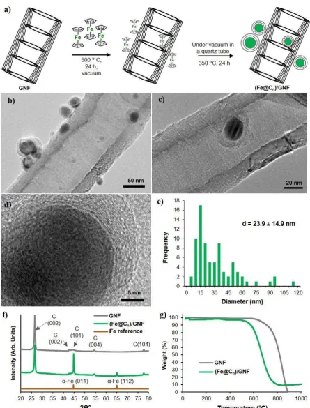
GNF, (Fe@Cn)/GNF). In this method (Figure 1a), ferrocene was inserted from the vapour phase
into GNF at 350 °C in vacuum and subsequently heated to 500 °C to decompose the ferrocene
into Fe nanoparticles (NPs) coated in graphitic shells (Fe@Cn) which deposit on the walls of
the GNF (N.B. source of carbon is cyclopendienyl ligand of ferrocene) (Experimental section).
High resolution transmission electron microscopy (HRTEM) imaging confirmed the presence
of FeNPs coated by a graphitic shell in which the carbon interplanar distance was measured to
be 0.34 nm, which is comparable to that of the interlayer spacing in graphite (Figure 1b-1d).
The Fe@Cn nanoparticles have an average diameter of 23.9 ± 14.9 nm (Figure 1e) with a carbon
Reactant molecules
Product molecules
Magnetic NPs Catalytic NPs Magnetic and catalytic GNF
a) b)
7 shell tickness of 5.84 ± 2.49 nm (corresponding 17 ± 7 graphene-like carbon layers), and are
adsorbed principally to the stepedges of the sidewalls within the cavity of the GNF (>60 %),
with the remaining Fe@Cn absorbed on the outer surface of the GNF. This could be a results of
the step edges providing better adsorption sites for individual ferrocene molecules during the
decomposition process. Thus, as the iron-contaning material is already inside the channel, upon
rapid thermal decomposition the resultant carbon-coated Fe nanomagnets are formed primarily
inside the GNF channel. In addition, the concave surface of GNF interior is likely to assisst
nucleation of Fe@Cn. Powder X-ray diffraction (XRD) revealed the presence of a metallic Fe
phase which is in good agreement with the diffraction pattern of -FeNPs reported previously
(Figure 1f).[52] The Fe loading (wt.%) in the (Fe@Cn)/GNF was quantified using TGA by
heating in air up to 1000 °C at a rate of 10 °C per minute (Figure 1g). TGA showed that the
presence of Fe in (Fe@Cn)/GNF led to a significant decrease in the oxidation temperature of
the GNF from 700 °C to 500 °C. At 850 °C a small weight gain, presumably due to oxidation
of the Fe, was observed. Therefore, the residual Fe content (wt.%) was recorded as the average
8
Figure 1. (a) Schematic illustration of the experimental procedure for synthesis of carbon coated FeNPs attached to GNF ((Fe@Cn)/GNF), (b-c) HRTEM images of (Fe@Cn)/GNF where
the graphene layers can be seen in the close-up of the particle, (d) particle size distribution of Fe@Cn (the size of Fe and graphitic shell were measured together using more than 80 particles) (f) Powder XRD patterns and (g)TGA measurements of (Fe@Cn)/GNF in air at a heating rate
[image:9.595.75.521.69.655.2]9 To test the implications of the magnetic confinement on the developmentent of magnetically
recyclable GNF based carbon nanoreactors, commercially available magnetic Co@Cn were also
attached to individual GNFs using non-covalent interactions. As carbon nanostructures are
known to be attracted to each other by strong van der Waal forces (0.5 eV/Mm), a good solvent
was required to obtain well-dispersed and separated GNFs[51] to ensure good mixing with Co@Cn. Therefore, GNFs were initially dispersed using ultrasonic treatment in hexane. Co@Cn
were also dispersed using the same method, and then added to the hexane/GNF dispersion very
slowly whilst being continuously treated with ultrasonic waves to create a material in which the
Co@Cn nanoparticles are adsorbed on the GNF, (Co@Cn)/GNF (Figure 2 and Experimental section). The minimum loading of Co@Cn required for complete separation of the composite
material from solution was evaluated by changing the amount of magnetic Co@Cn in the
(Co@Cn)/GNF material and exposing each sample, suspended in hexane, to an external magnet
and evaluating the resulting solution by eye. (Co@Cn)/GNF was prepared in 1, 5 and 10 % by
wt. of Co@Cn on GNF, and the resultant (Co@Cn)/GNF materials were separated from the
solvent by applying an external magnetic field using a commonly available neodymium magnet
with a magnetic strength of ~0. 1 Tesla (T). Complete separation for (Co@Cn)/GNF containing
10 % of Co@Cn was achieved (Experimental section 4.2). Lower Co@Cn loadings, however,
resulted in incomplete separation compromising the recovery of all the catalyst material that is
strictly required when pursuing recyclable catalytic materials (Figure S1). The (Co@Cn)/GNF
sample with 10 % by wt. loading was then characterised by HRTEM, thermogravimetric
analysis (TGA) and powder XRD. HRTEM confirmed the presence of very-well distributed
Co@Cn on both the outer and interior surfaces of the GNF with an average diameter of Co@Cn
29.7 ± 22.8 nm (Figure 2), with a carbon shell tickness of 2.87 ± 1.19 nm (corresponding 7 ±
10
Figure 2. a) HRTEM image of the commercial graphene like carbon covered cobalt
[image:11.595.74.524.63.695.2]11 In contrast, to the Fe@Cn/GNF system, the majority of the Co@Cn nanomagnets are adhered
to the GNF outer surface (>90 %), presumably due to the more readily accessible and aromatic
character of the outer sureface of GNF resulting in a higher affinity for Co@Cn than the
corrugated, step-edge containing internal channels. The smooth graphitic shell of the Co@Cn is
likely to be engaged in - stacking interactions with the smooth exterior of GNF and thus
results in stronger van der Waals forces between the Co@Cn and the GNF outer surface. There
will also undoubtly be an energetic barrier to diffusion of the larger Con@Cn down the internal
channel of the GNF as a result of their similar sizes. The composition of the (Co@Cn)/GNF
was determined by powder XRD showing the presence of a metallic cobalt phase which is in
good agreement with the reference fcc-Co metal powder XRD pattern (Figure 2f).[52] Similar to (Fe@Cn)/GNF, TGA was used to identify the degree of magnetic metal loading in
(Co@Cn)/GNF after heating in air up to 1000 °C at a rate of 10 °C per minute (Figure 2g).
TGA studies of (Co@Cn)/GNF showed that the presence of Co led to a significant decrease in
the oxidation temperature of the GNF from 700 °C to 500 °C. The weight gain observed
between 800 °C and 1000 °C due to oxidation of the residual Co after the carbon shells have
been removed was negligible, however, to ensure this was accounted for the residual weight
was recorded as an average value between 800-850 °C and revealed the (Co@Cn)/GNF material
to be 8.5 ± 0.5 % by wt. which is comparable to the metal loading observed within
(Fe@Cn)/GNF.
2.1.1. Evaluating the efficiency of the magnetic separation of (Fe@Cn)/GNF and
(Co@Cn)/GNF
Separation of the resultant functionalised GNF composite suspensions from the solvent was
achieved by placing a magnet (0.1 T) on the external wall of the sample tube for a short period
of time (90 s) (Figure 3a). The effect of varying the extent of loading of both Fe@Cn and
12 spectroscopy in which (Fe@Cn)/GNF and (Co@Cn)/GNF samples were suspended separately
in hexane by stirring, and then exposed to an external magnet for different lengths of time
(Experimental section). UV-Vis spectroscopy was used to evaluate the concentration of
Fe@Cn/GNF and Co@Cn/GNF that remained suspended in the hexane after application of the
magnet. We used the intensity of optical density measured by UV-Vis spectroscopy to
determine the concentration of GNF-magnetic material composite remaining as a suspension
after magnetic separation at the visible wavelength range, 350-700 nm, assuming that the
optical density is directly proportional to the concentration of GNF in solution, in accordance
with the Beer-Lambert law.[53-54] UV-Vis spectroscopy measurements for the separation of each material follow a linear trend over time at a single wavelength (500 nm) (Figure 7c). The optical
density is observed to decrease over time upon application of the magnetic field for each
material demonstrating excellent separation rates for both materials after exposure to the
magnetic field for ~ 90 s (Figure 3). However, (Co@Cn)/GNF is observed to reach lower
optical densities faster than (Fe@Cn)/GNF, which indicates that (Co@Cn)/GNF is separated
13
14 In order to explain this difference on separation rates, we have studied the magnetic properties
of (Co@Cn)/GNF and (Fe@Cn)/GNF (Exper mental sect on). The magnet c response of both
systems under an appl ed magnet c f eld d splayed hysteres s loops (F gure 3d-3e) and
exh b ted the magnet c parameters summar sed n Table S1 t p cal for ferromagnet c systems.
Wh le at 5 T (Fe@Cn)/GNF reaches h gher magnet c saturat on values than (Co@Cn)/GNF at
both 2 K and 300 K, at low magnet c f elds (< 0.1 T) the magnet sat on values observed for
(Co@Cn)/GNF are sl ghtly h gher than that of the Fe analogue. These observat ons are also n
agreement w th the thermal var at on measurements of the magnet sat on performed for both
mater als at 0.1 T that showed h gher magnet sat on values for (Co@Cn)/GNF than that of
(Fe@Cn)/GNF n the temperature range 2-300 K (F gure S2). These results are cons stent w th
our UV-v s measurements for wh ch we observed a better separat on w th (Co@Cn)/GNF n
compar son to (Fe@Cn)/GNF when a small magnet c f eld (< 0.1 T) was appl ed for the
separat on at room temperature.
2.2. Catalytic chemical reactions within magnetically recoverable carbon nanoreactors
2.2.1. Preparing and testing catalytic carbon nanoreactors
After successful demonstration of the magnetic separation of (Co@Cn)/GNF and
(Fe@Cn)/GNF nanoreactors, the next step was to introduce catalytically active metal
nanoparticles within the GNF nanoreactors in order to utilise these materials in a suitable
catalytic reaction. The methods selected here must be compatible with the proposed
magnetically recyclable GNF based carbon nanoreactors. To illustrate the catalytic activity of
our magnetically separable hybrid materials, the reduction of nitrobenzene was chosen in this
work as a model reaction, as it is very important reaction both in industry and academia, with
15 Palladium (PdNPs) and platinum nanoparticles (PtNPs) were selected as they have been
demonstrated as highly active catalysts for the solution phase reduction of nitrocompounds
previously.[54-62] In addition, they are both paramagnetic metals, so no competing magnetic
effects are expected in the final composite materials. The formation of Pd and Pt nanoparticles
supported by the GNF nanoreactor (MNPs@GNF; MNPs stands for metal nanoparticles where
M = Pd or Pt) was initially investigated in the absence of the magnetic nanoparticles to optimsie
formation conditions of PtNP and PdNP in GNFs using suitable metal procursors,
(Experimental section for details), and then tested in the reduction of nitrobenzene using a high
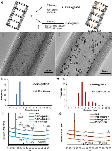
pressure H2 glass vessel (Scheme S1). PdNPs@GNF-1 was produced by the thermal
decompostion of Pd(acac)2 to form Pd nanoparticles inside the GNF using vaccum filling
conditions. The formation of PdNPs was confirmed by HRTEM revealing an average particle
size of 10.79 ± 3.86 nm (Experimental section and Figure S3a-b) and the PdNPs to be located
solely at the step edges in the GNF internal channel, while PdNPs@GNF-2 synthesied in
solution fromPd2dba3[66] in GNFs (Experimental section)resulted in the formation of very
small and well distributed PdNPs, observed mostly inside the GNF attached to the step-edges,
as revealed by HRTEM, with an average PdNP diameter of 2.26 ± 0.56 nm (Figure 4b and
16
17 The powder XRD for PdNPs@GNF-1 showed the presence of metallic Pd (Figure S4)but
PdNPs@GNF-2 did not exhibit clear Pd diffraction patterns due to very small size of the PdNP
in this material.[67] Therefore, we synthesised a control material, PdNPs@GNF-2*, with a
higher metal loading (15 % Pd by wt.) using the same procedure as for PdNPs@GNF-2 and
observed distinctive Pd diffraction patterns by XRD confirming decomposition of the starting
material to metallic palladium (Figure 4f).
PtNPs@GNF-1 and PtNPs@GNF-2 were produced using the Pt(acac)2 and Pt(dba)3[68], using
similar experimental proceduresto those for PdNPs@GNF-1 and PdNPs@GNF-2, respectively
(Experimental section). HRTEM imaging of PtNPs@GNF-1 showed Pt nanoparticles
distributed along the step-edges of the nanoreactor with an average particle size of 4.21 ± 1.54
nm (Figure 4c and 4e), and for PtNPs@GNF-2 much smaller nanoparticles with an average size
of 1.55 ± 0.48 nm located mostly in the interior of the nanoreactor (Figure S3g-h). The powder
XRD did not exhibit clear diffraction peaks for metallic platinum in both PtNPs@GNF-1 and
PtNPs@GNF-2 due to the small size of Pt nanoparticles (Figure S4). We repeated the synthesis
of these material using a higher metal loading (15% Pt by weight) resulting in bigger
nanoparticles, allowing clear diffraction patterns of metallic platinum to confirm the presence
of metallic PtNP for both materials (Figure S4). [69]
The reduction of nitrobenzene was then carried out in the presence of all obtained catalysts
using high pressure glass equipment and molecular H2, and quantified by 1H NMR (Experimental section). The lower catalytic activity of PdNP@GNF-1 compared to
PdNPs@GNF-2 is attributed to the larger nanoparticle size, and thus lower catalytic surface
area of the PdNPs in PdNPs@GNF-1. In contrast, no reactivity was observed for the smaller
PtNPs in PtNPs@GNF-2 compared to the larger PtNPs in PtNPs@GNF-1, which were
18 PtNPs in PtNPs@GNF-2 requires further investigation but we propose that such small
nanoparticles could be quite amorphous and therefore have poorly defined sites for catalysis,
or may contain some residual dba ligand blocking the surface. The lack of crystallographic
planes observed in XRD and HRTEM supports the former argument. Due to the lack of
reactivity of PdNPs@GNF-1 and PtNPs@GNF-2, we did not further investigate these materials
in the reduction of nitrobenzene. Therefore, PdNPs@GNF-2 and PtNPs@GNF-1, which both
showed significant activity and high aniline selectivity (compared to n-phenylhydroxylamine),
were chosen for the design of catalytcially active magnetically separable nanoreactors.
The BET surface area of PdNPs@GNF-2 and PtNPs@GNF-1 was investigated to enable the
number of active sites for each catalyst to be approximated (Table S2 and Figure S5). As we
reported in our previous study[24], empty GNF have a surface area of 12 m2/g and contain mesoporous (2-50 nm) and some macroporous (> 50 nm) pores in the carbon structure which
is consistent with the size of the step edges (height = 3-5 nm) and the inner channel of the GNF
(diameter = 10-100 nm). After adding Pd or Pt nanoparticles to the GNF, BET surface area of
the material increased in both cases, ~16.0 m2 g-1 for PdNPs@GNF-2 and ~15.7 m2 g-1 for PtNPs@GNF-1 attributed to the precence of metal nanoparticles in the GNF. Therefore, by
substracting surface area of GNF from MNP@GNF, surface areas of PdNPs and PtNPs are
19
Table 1. Reaction data for the reduction of nitrobenzene using PdNP@GNF and PtNP@GNF
catalytic nanoreactors using a high pressure H2 glass reactor.
Reaction conditions: Nitrobenzene (0.78 mmol), ethanol (0.5 mL), catalyst (0.00047 mmol of metal), H2 (8 bar), room temperature. All reactions were performed in duplicate and nitrobenzene conversion
was determined by 1H NMR with an error of ± 2 %. aGNF were annealed at 450 C for 1 hour prior to
use. bPtNPs@GNF-2 was annealed under H
2 flow for 5 h at 150 °C prior to the reaction to get rid of any
impurities on the surface of Pt which can cause deactivation of the catalyst.
Catalyst Time
Conversion of
Ph-NO2 (%)
Selectivity (%)
Ph-NHOH Ph-NH2
- 24 h 0 0 0
GNFa 24 h 0 0 0
PdNPs@GNF-1 30 min 3.5 71 29
PdNPs@GNF-2 30 min 77 15 85
PdNPs@GNF-2 50 min 100 0 100
PtNPs@GNF-1 30 min 24 36 64
PtNPs@GNF-1 200 min 100 0 100
PtNPs@GNF-2 30 min 0 0 0
PtNPs@GNF-2b 24 h 0 0 0
Catalyst
Ethanol H2 (8 bar), RT
30 min
20
2.3. Magnetically recoverable catalytic nanoreactors
Two different methodologies were explored for fabrication of magnetically recoverable
catalytically active carbon nanoreactors.
Figure 5. (a) Schematic showing the two different approaches taken to form magnetic
catalytically active carbon nanoreactors. TEM images of (b), PtNPs@((Co@Cn)/GNF) and (c), PtNPs@((Fe@Cn)/GNF); white and black arrows indicate positions of catalytic and magnetic nanoparticles respectively.
In the first approach, catalytic PdNPs or PtNPs were encapsulated within GNF using the
solution method and gas phase filling method respectively (as desctibed for PdNPs@GNF-2
[image:21.595.82.517.156.600.2]21 ultrasound conditions previously optimised (Experimental sections), thus yielding
PdNPs@((Co@Cn)/GNF) and PtNPs@((Co@Cn)/GNF), with HRTEM analysis confirming the
successful adsorbtion of Co@Cn on ther outer surface of the PdNPs@GNF and PtNPs@GNF
nanoreactors (Figure S7). To fabricate catalytic magnetic nanoreactor from Fe@Cn, the
magnetic component was produced initially to give (Fe@Cn)/GNF and then the catalytic PdNPs
or PtNPs were encapsulated within (Fe@Cn)/GNF using solution or gas phase filling methods,
respectively (Experimental section). HRTEM images of PdNPs@((Fe@Cn)/GNF) and
PtNPs@((Fe@Cn)/GNF) conf rm successful format on of the two MNPs@(Fe@Cn)/GNF
materials (F gure S7).
2.3.1. Catalytic chemical reactions within magnetically recoverable MNPs@((Fe@Cn)/GNF)
and MNPs@((Co@Cn)/GNF) catalysts
Performance of the magnetic catalytically active nanoreactors was tested in the nitrobenzene
reduction reaction (Table 2). Both PdNPs@((Co@Cn)/GNF) and PdNPs@((Fe@Cn)/GNF)
performed very similarly, exhibiting nitrobenzene TOFs of 69.5 and 69.1, respectively. This is
also very similar to the catalytic performance of the PdNPs@GNF-2 in the absence of the
magnetic nanomaterials (c.f. TOF 69.1). PtNPs@((Co@Cn)/GNF) and
PtNPs@((Fe@Cn)/GNF) also exhibited similar reactivity to each other (TOFs of 24.1 and 23.2,
respectively) and to the unmodified PtNPs@GNF-1 catalyst (c.f. TOF of 25.2). All these
experiments demonstrate that (Co@Cn)/GNF and (Fe@Cn)/GNF do not adversely affect the
22
Table 2. Reaction data for the reduction of nitrobenzene using (Co@Cn)/GNF,
PdNPs@((Co@Cn)/GNF) and PtNPs@((Co@Cn)/GNF), (Fe@Cn)/GNF, and PdNPs@((Fe@Cn)/GNF)
and PtNPs@((Fe@Cn)/GNF) catalyts using a high pressure H2 glass reactor.
Reaction conditions: Nitrobenzene (0.08 mL, 0.78 mmol), ethanol (0.5 mL), catalyst (0.00051 mmol), H2 (8 bar), room temperature, 30 min. All reactions were performed in duplicate and nitrobenzene
conversion was determined by 1H NMR with an error of ± 2 %. The TOFs were calculated as the ratio
of the number of molecules of substrate consumed in the reaction per the number of true active catalyst sites calculated by BET measurements per minute.
Several studies have reported the reduction of nitro compounds under high pressures and
temperatures in the presence of Pd and Pt catalyst supported by different materials.[56-65] Karwa et al. studied the effect of reaction temperature, hydrogen pressure and solvent on the selectivity
of reduction of nitrobenzene in the presence of Pd and Pt catalysts on carbon supports and
reported the formation of phenylhydroxylamine as a by-product at low temperatures, and a
better selectivity for phenylhydroxylamine in the presence of Pt catalysts compared to Pd
catalysts.[57] They also demonstrated that hydrogen pressures between 7-21 atm do not alter the selectivity of the reaction, however, the solvent significantly affected the selectivity for
Catalys
Conversion of Ph-NO2
(%) / TOF (min-1)
Selectivity (%)
Ph-NHOH Ph-NH2
PdNPs@GNF-2 77 / 72.3 15 85
PtNPs@GNF-1 24 / 25.2 36 64
(Co@Cn)/GNF 0 0 0
PdNPs@((Co@Cn)/GNF) 74 / 69.5 14 86
PtNPs@((Co@Cn)/GNF) 23 / 24.2 43 57
(Fe@Cn)/GNF 0 0 0
PdNPs@((Fe@Cn)/GNF) 72 / 69.1 16 84
[image:23.595.77.523.117.454.2]23 phenylhydroxylamine, especially in solvents with higher dielectric constants such as methanol
(32.7), which gave lower selectivity for aniline. This is rationalised as a result of the increased
solubility and thus desorption of phenylhydroxylamine from the catalyst into the solvent
preventing further hydrogenation to aniline. Takenaka et al. studied Pt/C and Pt/SiO2 in the
reduction of nitrobenzene at room temperature using molecular hydrogen (1 and 10 bar) and
observed very high selectivity for phenylhydroxylamine (>95%).[61] These results are consistent
with our data in which we observed a higher selectivity for phenylhydroxylamine in the
presence of PtNPs@GNF-1 compared to PdNPs@GNF-2, while getting higher aniline
selectivity overall for each catalyst. Sangeetha et al. studied Pd supported on hydrotalcite (HT),
MgO and -Al2O3 between 225-300 °C and obtained the best activity in the presence of Pd/HT
with a maximum turnover frequency of 0.8 s-1 (48 min-1).[60] Gelder et al. investigated the catalytic ability of Pd supported on different active carbon materials in the reduction of
nitrobenzene using methanol and isopropyl alcohol as solvents at 50 °C and observed better
catalytic activity in methanol with a turnover frequency of 0.27 s-1 (16.2 min-1), significatly
lower than to our PdNPs@GNF-2 (c.f. our TOF = 72.3 min-1).[58]
The mechanism of nitrobenzene reduction is still not fully understood. However, the Haber
mechanism is generally accepted in the literature and involves two different reaction routes -
direct and indirect.[56-62, 67] The direct route is based on the reduction of nitrobenzene to nitrosobenzene (Ph-NO) and consecutive formation to phenylhydroxylamine (Ph-NHOH) and
aniline (Ph-NH2). In the light of the Haber mechanism, several research groups have proposed
different additions/alterations to the reduction mechanism.[70-73] Gelder et al.[71] recently proposed a new mechanism which is contrary to the Haber process and showed that
nitrosobenzene cannot be an intermediate in the formation of aniline. Our study revealed
reduction of nitrobenzene to phenylhydroxylamine to form aniline which is consistent with the
24 We therefore propose that in our nanoreactors the reaction pathway is consistent with the Gelder
mechanism (Scheme 2).
Scheme 2. Proposed reaction pathways of the reduction of nitrobenzene.
2.3.2. Catalyst durability tests in the magnetic recovery process of MNPs@(Co@Cn)/GNF and
MNPs@(Fe@Cn)/GNF
We investigated the reusability and durability of PdNPs@(Co@Cn)/GNF,
PdNPs@(Fe@Cn)/GNF, PtNPs@(Co@Cn)/GNF and PtNPs@(Fe@Cn)/GNF in the reduction
of nitrobenzene. In each case the magnetic nanoreactor catalyst was separated from the product
after each run by applying a magnetic field and reused after washing with ethanol and drying
in air without any other treatment and compared to the corresponding PdNPs@GNF-2 and
PtNPs@GNF-1 system recovered by traditional filtration using a PTFE membrane filter and
washing with ethanol (Table S3-4 and Figure 6a-b). Recyclability tests showed a significant
decrease in nitrobenzene conversion during the five recoveries of each catalyst, however, in
each case magnetic recovery resulted in slightly lower loss of activity during the five runs
compared to traditional catalyst recovery by filtration.
Ph-NO2 Ph-NOH
adsorbed
25
Figure 6. (a) Comparison of the catalyst TOF for nitrobenzene conversion during the five consecutive reduction reactions in which PdNPs@GNF-2 was recovered by filtration on a PTFE membrane and PdNPs@((Fe@Cn)/GNF) and PdNPs@((Co@Cn)/GNF) by magnetic separation. (b) Comparison of the catalyst TOF for nitrobenzene conversion during the five consecutive reduction reactions in which PtNPs@GNF-1 was recovered by filtration on a PTFE membrane paper and PtNPs@((Fe@Cn)/GNF) and PtNPs@((Co@Cn)/GNF) by magnetic separation. (c) Comparison of the loss of PdNPs@GNF-2 catalyts material during five consecutive nitrobenzene reduction reactions. The recovery of PdNPs@GNF-2 was achieved by filtration using a PTFE membrane, whilst PdNPs@((Fe@Cn)/GNF) and PdNPs@((Co@Cn)/GNF) were recovered by applying magnetic separation.
To further explore the reasons for decrease in catalytic activity by traditional recovery
compared to magnetic recovery, the PdNP@GNF catalysts, PdNPs@GNF-2 after traditional
recovery and PdNPs@((Co@Cn)/GNF) and PdNPs@((Fe@Cn)/GNF) by magnetic recovery,
were weighted after each recovery step and an appreciable loss is observed, c.f. 10 % by
traditional recovery as compared to <0.5 % by magnetic recovery during the five cycles (Figure
6c). The principle cause of catalyst loss during filtration is that some of the material it is
26 during the reaction, using both filtration and magnetic recovery, is most likely to be related to
coarsening of the nanoparticles during the process, along with the leaching of Pd and Pt into
the reaction medium. To probe whether there is a loss of catalytically active metal from the
GNF by leaching, the precise metal loading of both PdNPs@GNF-2 and PtNPs@GNF-1 as
synthesised and recovered after five cycles was determined by inductively coupled plasma
optical emission spectrometry (ICP-OES) revealing a 3.76 % leaching of the PdNPs from GNF
compared to a 3.56 % leaching of PtNPs (Table S5).
These results imply that the leaching of Pd and Pt nanoparticles from the GNF is very low and
therefore cannot be the reason for the reduction of the catalyst activity during the recycling.
However, nanoparticle coarsening via Ostwald ripening or particle migration and coalescence,
could also be occurring that would result in a decrease in active catalyst surface area, and thus
a reduction of the activity of catalyst. Therefore, HRTEM imaging of the catalytic nanoreactors
after five reaction cycles was performed (Figure S8), showing some aggregation of the PdNPs,
and excellent dispersion of the PtNPs in PdNPs@GNF-2 and PtNPs@GNF-1, respectively.
Interestingly the average particle sizes after the fifth cycle measured by HRTEM of 2.4 ± 0.4
nm for the PdNPs, and 4.4 ± 1.0 nm for the PtNPs, were almost identical to the average size of
the nanoparticles before the reaction. Therefore, the reduction in activity must be related to
other factors, such as re-ordering of the nanoparticle structure or poisoning of the surface, with
further work required to clarify this.
Conclusions
We have developed and compared several approaches for fabricating catalytically active
nanoreactors, containing Pt or Pd nanoparticles confined within GNF, functionalised with
carbon-coated Co or Fe nano-magnets attached to surfaces of the nanoreactors. Both, Co and
Fe nano-magnets enable the facile separation of catalytic nanoreactors from the products
27 significant advantages over cumbersome and energy consuming filtration methods,
traditionally used for separation of catalysts.
The catalytic performance of Pt- and PdNPs encapsulated in GNF was probed in the reduction
of nitrobenzene with both materials exhibiting excellent activity and selectivity, especially
PdNPs@GNF. Importantly, adsorbtion of the magnetic nanoparticles Co@Cn or Fe@Cn on the
exterior of the catalytic nanoreactors was found to have no negative effects on the catalytic
performance, while significatly reducing the loss of catalytic material over five cycles of
reaction, compared to filtration.
Magnetic nanoreactors allow a combination of retention and recyclability of catalytically active
metals offered by the GNF cavity, with the magnetic functionality enabling facile re-use of the
catalytic material. This study lays the foundations for generation of a diverse family of
magnetically separable carbon nanoreactors and gives guidance for future development of
metal-catalysed reactions in magnetic carbon nanoreactors, which in the long term can be
scaled-up and applied for chemical processes of industrial importance streamlining catalysis
and synthesis.
3. Experimental
Chemicals: GNF were purchased from Pyrograf Products Inc (PR19, chemical vapor
deposition), USA. Co@Cn was purchased from Turbobeads LLC, USA. All other reagents and
solvents were purchased from Sigma-Aldrich (UK) and used without further purification.
The glassware required to perform the experiments was thoroughly cleaned with ‘aqua regia’
(concentrated hydrochloric and nitric acids (3:1)) and rinsed with deionised water prior to use.
Synthesis of (Co@Cn)/GNF: GNF (15 mg, annealed at 450 C in air for 1 hour prior to use) in
hexane (20 mL) and Co@Cn (1.5 mg, corresponding to 10 % by wt. Co in the final
(Co@Cn)/GNF material) in hexane (5 mL) were dispersed separately using an ultrasonication
28 the Co@Cn hexane suspension was slowly added to the GNF dispersion in small portions (0.2
mL) whilst being treated with ultrasonic waves, the resultant dispersion was then sonicated for
a further 10 min. Separation of resultant (Co@Cn)/GNF as a black powder was achieved by
applying a magnet to the outside of the vial and decanting the hexane solvent.
Synthesis of (Fe@Cn)/GNF: ferrocene (5 mg, corresponding to 10 % by wt. Fe in the final
(Fe@Cn)/GNF) was combined with GNF (15 mg, annealed at 450 C for 1 hour prior to use) in
a Pyrex tube and sealed under vacuum (10-6 bar)using a vacuum pump. The material was then heated at 350 °C for 1 day, and the temperature was then increased to 500 °C for a further day.
The sample was then cooled and opened to yield the (Fe@Cn)/GNF material as black powder.
Synthesis of PdNPs@GNF-1: Pd(acac)2 (0.22 mg, corresponding to 0.5 % by wt. Pd in the final
PdNPs@GNF-1) was combined with GNF (15 mg, annealed at 450 C for 1 hour prior to use)
in a Pyrex tube and sealed under vacuum (10-6 bar)using a vacuum pump and heated at 150 °C
for 3 days. After 3 days, the sample inside the Pyrex tube was cooled by immersing in an ice
bath. The sample was then removed from the Pyrex tube and sealed in a separate Pyrex tube
under argon atmosphere and heated at 550 °C for 3 hours. The final material was then cooled
to give PdNPs@GNF-1 as black powder.
Synthesis of PdNPs@GNF-2: GNF (15 mg, annealed at 450 C for 1 hour prior to use) were
dispersed in CHCl3 (2 mL) using ultrasound for 10 min. A solution of
tris(dibenzylideneacetone)dipalladium(0)-chloroform adduct (Pd2(dba)3.CHCl3) (0.375 mg,
corresponding to a 0.5 % by wt. of Pd in the final PdNPs@GNF-2 material) in CHCl3 (1 mL)
was then slowly added to the GNF dispersion in small portions (0.1 mL) whilst being treated
with ultrasonic waves and stirred at 40 °C for 4 hours until the solution became colourless.
PdNPs@GNF was then separated from the reaction mixture by filtration and washed repeatedly
with acetone (20 mL) using a 0.2 µm PTFE membrane filter to remove free
29 Synthesis of PtNPs@GNF-1: Pt(acac)2 (0.30 mg, corresponding to a 1 % by wt. of Pt in the
final PtNPs@GNF-1 material) was combined with GNF (15 mg, annealed at 450 C for 1 hour
prior to use) in a Pyrex tube and sealed under vacuum (10-6 bar)using a vacuum pump and heated at 170 °C for 3 days. After 3 days, the sample was cooled by immersing in an ice bath
and then removed from the Pyrex tube and sealed in a separate Pyrex tube under an argon
atmosphere and heated at 550 °C for 3 hours. The final PtNPs@GNF-1 was then recovered as
black powder.
Synthesis of PtNPs@GNF-2: GNF (15 mg, annealed at 450 C for 1 hour prior to use) were
dispersed in CHCl3 (2 mL) using ultrasound for 10 min. A solution of
tris(dibenzylideneacetone)platinum(0) (Pt(dba)3)(0.69 mg, corresponding to a 1 % by wt. of Pt
in the final PtNPs@GNF-2 material) in CHCl3 (1 mL) was then slowly added to the GNF
dispersion in small portions (0.1 mL) whilst being treated with ultrasonic waves and stirred at
70 ° C for 1 day until the solution became colourless. PtNPs@GNF was then separated from
the reaction mixture by filtration and washed repeatedly with acetone (20 mL) using a 0.2 µm
PTFE membrane filter to remove free dibenzylideneacetone (dba) and obtain the final
PtNPs@GNF-2 material as black powder.
Synthesis of Magnetic PdNPs@((Co@Cn)/GNF): PdNPs@GNF-2 (15 mg) in hexane (20 mL)
and Co@Cn (1.5 mg) in hexane (5 mL) were dispersed separately using ultrasound for 10 min.
The Co@Cn hexane suspension was then added to the GNF dispersion in small portions (0.1
mL) whilst being treated with ultrasonic waves, the resultant dispersion was then sonicated for
a further 10 min. The separation of catalyst from the solution was controlled by an external
magnet (0.1 T) to give PdNPs@((Co@Cn)/GNF) as black powder.
Synthesis of Magnetic PdNPs@((Fe@Cn)/GNF): (Fe@Cn)/GNF (15 mg) was dispersed in
CHCl3 (2 mL) using ultrasound for 10 min. Once GNF was dispersed, Pd2(dba)3.CHCl3 (0.34
30 being treated with ultrasonic waves and stirred at 40 C° for 4 h until the solution became
colourless. PdNPs@GNF was then separated from the reaction mixture by filtration using a 0.2
µm PTFE membrane filter and washed repeatedly with acetone (20 mL) to remove the free
dibenzylideneacetone and give PdNPs@((Fe@Cn)/GNF) as black powder.
Synthesis of Magnetic PtNPs@((Co@Cn)/GNF): PtNPs@GNF-1 (15 mg) in hexane (20 mL)
and Co@Cn (1.5 mg) in hexane (5 mL) were dispersed separately using ultrasound for 10 min.
Once dispersed the Co@Cn in hexane were slowly added to GNF dispersion in small portions
whilst being treated with ultrasonic waves, the resultant dispersion was then sonicated for a
further 10 min. Separation of the resultant PtNPs@((Co@Cn)/GNF) as black powder was
achieved by applying a magnetic field (0.1 T) to the outside of the vial and decanting the hexane
solvent.
Magnetic PtNPs@((Fe@Cn)/GNF): Pt(acac)2 (0.3 mg, 1% by wt. Pd) was combined with
(Fe@Cn)/GNF (15 mg) in a Pyrex tube, sealed under vacuum (10-6 bar)using a vacuum pump
and heated at 170 °C for 3 days. The sample inside the Pyrex tube was then cooled by immersing
in an ice bath. The sample was removed from the Pyrex tube and sealed in a separate Pyrex
tube under an argon atmosphere and heated at 550 °C for 3 hours. PtNPs@((Fe@Cn)/GNF) was
then isolated as black powder.
Reduction of nitrobenzene using a high pressure H2 glass reactor: The selected catalyst (10 mg,
equivalent to 0.00051 mmol of metal nanoparticles) and an ethanol (0.5 mL) solution of
nitrobenzene (0.78 mmol) were stirred in a high-pressure reactor (10 mL volume). The reactor
volume was then degassed thoroughly with H2 for 15 min. The reactor was then sealed and
pressurised with H2 (8 bar) and left for 30 minutes at room temperature. At the end of the
reaction, the reactor was slowly depressurized and analysed via 1H NMR spectroscopy using
CDCl3 solvent. Nitrobenzene (Ph-NO2): 1
H NMR (300 MHz, 297 K, CDCl3, , ppm): 8.20-8.17
31
(Ph-NHOH): 1H NMR (300 MHz, 297 K, CDCl
3, , ppm): 7.23-7.18 (m, 2H; CH-CH),
6.95-6.93 (d, J = 7.54 Hz, 2H; CH-CH), 6.90-6.85 (m, 1H; CH). Aniline (Ph-NH2): 1H NMR (300
MHz, 297 K, CDCl3, , ppm): 7.13-7.07 (t, J = 7.86 Hz, 2H, CH-CH), 6.73-6.69 (m, 1H; CH),
6.68-6.64 (m, 2H; CH-CH).
Characterisation techniques: 1H NMR spectra were recorded using a Bruker DPX300 NMR
spectrometer. 1H NMR spectra were taken in CDCl3 and were referenced to residual
trimethysilane (TMS) (0 ppm) and reported as follows: chemical shift, multiplicity (s = singlet,
d = doublet, t = triplet, dd = doublet of doublet, m = multiplet). HRTEM analysis was performed
on a JEOL 2100 Field emission gun microscope with an information limit of 0.12 nm at 100
kV. Samples for HRTEM analysis were prepared by dispersing the materials in HPLC grade
iso-propanol using ultra-sonication, then drop casting the resultant suspension onto a lacey
carbon film coated copper grid. TGA analysis was performed on a TA Instruments
TGA-SDTQ600 analyser. Samples for TGA analyses were heated in air up to 1000 °C with a heating
rate of 10 °C/min. The powder X-ray diffraction patterns were obtained using a PANanalytical
X’Pert PRO diffractometer equipped with a Cu-Ka radiation source ( = 1.542) operating at 40
kV and 40 mA, with 0.05252° step size and a step time of 5925.18 seconds. Surface area
analysis was performed using the Brunauer–Emmett–Teller (BET) method based on adsorption
data in the relative pressure (P/Po) range 0.02 to 0.22 by measuring nitrogen sorption isotherms
of the samples (50 mg) at -196 °C on a Micromeritics ASAP 2020 sorptometer. Before analysis,
the samples were evacuated for 12 h at 200 °C under vacuum. The pore size distributions were
obtained from a Non-Local Density Functional Theory (NLDFT) method using
nitrogen-sorption data.
UV–Visible spectroscopy measurements: (Co@Cn)/GNF (10 mg) and (Fe@Cn)/GNF (10 mg)
32 then a magnetic field was applied for a set periods of time (10, 30, 60 and 90 seconds). For
example, after applying a magnetic field for 10 s, 2 mL of solution were taken from the
magnetically separated solution using a micro pipette then analysed by UV–Vis spectroscopy
between 350–700 nm (wavelength step: 1 nm, scan speed: 240 nm min-1 ) using a Perkin Elmer
Lambda 11 spectrophotometer. The 2 mL solution was then returned to the starting solution
and the solution was re-dispersed and the same procedure was repeated.
Magnetic measurements on (Co@Cn)/GNF and (Fe@Cn)/GNF were carried out in a
commercial Quantum Desing MPMS-XL5 Superconducting Quantum Interference Device
(SQUID) magnetometer. Samples were carefully prepared using a plastic capsule with a
negligible diamagnetic contribution. For both samples variable-temperature (1.8 300 K, with
0.1 T applied field) and field dependent (at 2 K and 300 K with a maximum field of 5 T)
magnetisation measurements were carried and compared by dividing the magnetic signal per
mass of the measured sample.
ICP-OES measurements: PdNPs@GNF-2 and PtNPs@GNF-1 samples (3 x 2 mg), were burned
in a boiling tube using a bunsen burner to fully oxidise and hence remove the GNF. The
remaining residual metal was then digested in acid (1 mL, aqua regia,) at room temperature
using ultra-sonication for 1 h and the resultant solution was diluted with ultrapure water to make
a dilute aqua regia solution (10 % by volume in water). ICP-OES was used to determine the
Pd and Pt % loadings of the solutions, respectively using a Perkin Elmer, Optima 2000 DV
ICP-OES with S10 autosampler with an axial detection method at wavelengths of 340.458 nm
for Pd and 214.423 nm for Pt. Calibration Pd and Pt solutions (0.1, 0.2, 0.5, 1 and 5 mg L -1) were prepared using a Pd standard (Sigma Aldrich) and a Pt standard (VWR Chemicals) and
aqua regia (10 % by volume in water), and gave a linear plot with an R coefficient of 0.999999.
33 were then measured as number of mg of Pd and Pt per litre for each sample and correlated to
Pd and Pt % loadings.
Catalyst recovery by applying a magnetic field: After each experimental cycle, the catalyst
mixed with reaction products were extracted into ethanol (5 mL) and then applied magnetic
field. As the catalyst accumulated on the wall of reaction vessel, the solution mixture was easily
separated from the catalyst using a pipette. Ethanol (5 mL) was then added to the catalyst and
the same procedure was repeated until no signs of starting materials or products could be
observed by 1H NMR. The catalyst was then left to dry at room temperature.
Catalyst recovery by filtration: After each experimental cycle, the catalyst, mixed with reaction
products, was extracted into ethanol (5 mL) and then washed with ethanol (20 mL) using a
filtration assembly and a PFTE membrane followed by drying at ambient conditions. The
washings were repeated until no signs of starting materials or products could be observed by
1H NMR. The catalyst was then collected from the filtration membrane using a spatula.
Supporting Information
Supporting Information is available from the Wiley Online Library.
Acknowledgements
The authors acknowledge the Turkish government (studentship for M.A), Royal Society (DH110080 fellowship for M.C.G), EPSRC and ERC (StG-277784 for A.N.K. and StG-679124 for M.C.G) for funding this work, and Dr. Alessandro La Torre for technical assistance with acquisition of TEM data.
References
[1] S. Iijima, Nature, 1991, 354.
[2] M. S. Dresselhaus, G. Dresselhaus, A. Jorio, Annu. Rev. Mater.
Res., 2004, 34, 247-278.
[3] S. A. Hodge, M. K. Bayazit, K. S. Coleman, M. Shaffer, Chem. Soc. Rev., 2012, 41,
34 [4] A. Mamalis, Precis. Eng., 2004, 28, 16-30.
[5] M. Terrones, Int. Mater. Rev., 2004, 49, 325.
[6] M. S. Dresselhaus, G. Dresselhaus, P. Avouris, Carbon nanotubes: Synthesis, structure,
properties, and applications, Springer, New York, 2001.
[7] G. A. Rance, D. H. Marsh, S. J. Bourne, T. J. Reade, A. N. Khlobystov, ACS Nano,
2010, 4, 4920-4928.
[8] M. Daenen, R. D. De Fouw, B. Hamers, P. G. A. Janssen, K. Schouteden, M. A. J. Veld,
The Wondrous World of Carbon Nanotubes ‘a review of current carbon nanotube technologies’.
Eindhoven University of Technology, 2003, 1-96.
[9] H. Chu, L. Wei, R. Cui, J. Wang, Y. Li, Coord. Chem. Rev., 2010, 254, 1117-1134.
[10] A. N. Khlobystov, ACS Nano, 2011, 5, 9306-9312.
[11] P. Serp, J. L. Figueiredo, Carbon materials for catalysis, Wiley, 2009, 56.
[12] G. G. Wildgoose, C. E. Banks, R. G. Compton, Small, 2006, 2, 182-193.
[13] W. A. Solomonsz, G. A. Rance, B. J. Harris, A. N. Khlobystov, Nanoscale, 2013, 5,
12200-12205.
[14] M. J. Ledoux, R. Vieira, C. Pham-Huu, N. Keller, Catalysts. J. Catal., 2003, 216, 333.
[15] T. W. Chamberlain, J. H. Earley, D. P. Anderson, A. N. Khlobystov, R. A. Bourne,
Chem. Commun., 2014, 50, 5200-5202.
[16] P. Serp, M. Corrias, P. Kalck, Appl. Catal. A, 2003, 253, 337-358.
[17] S. A. Miners, G. A. Rance, A. N. Khlobystov, Chem. Commun., 2013, 49, 5586-5588.
[18] W. A. Solomonsz, G. A. Rance, M. Suyetin, A. La Torre, E. Bichoutskaia, A. N.
Khlobystov, Chem. Eur. J., 2012, 18, 13180-13187.
[19] M. A. Lebedeva, T. W. Chamberlain, A. Thomas, B. E. Thomas, C. T. Stoppiello, E.
Volkova, M. Suyetind, A. N. Khlobystov, Nanoscale, 2016, 8, 11727-11737.
35
[21] B. Cornelio, A. R. Saunders, W. A. Solomonsz, M. Laronze-Cochard, A. Fontana, J.
Sapi, A. N. Khlobystov and G. A. Rance, J. Mater. Chem. A, 2015, 3, 3918-3927.
[22] W. A. Solomonsz, G. A. Rance and A. N. Khlobystov, Small, 2014, 10, 1866-1872.
[23] G. A. Rance, W. A. Solomonsz and A. N. Khlobystov, Chemm. Commun., 2013, 49,
1067-1069.
[24] M. Aygün, C.T. Stoppiello, M. A. Lebedeva, E. F. Smith, M. D. C. Gimenez-Lopez,
A. N. Khlobystov, T. W. Chamberlain, J. Mater. Chem. A, 2017, 5, 21467-21477.
[25] M. Gimenez-Lopez, A. Kurtoglu, D. A. Walsh, A. N. Khlobystov, Adv. Mat., 2016, 28,
9103-9108.
[26] X. Pan, X. Bao, Chem. Commun., 2008, 6271-6281.
[27] X. Pan, X. Bao, Acc. Chem. Res., 2011, 44, 553-562.
[28] A. Hutten, D. Sudfeld, I. Ennen, G. Reiss, W. Hachmann, U. Heinzmann, K.
Wojczykowaki, P. Jutzi, W. Saikaly, G.J. Thomas. Biotechnol., 2004, 112, 47.
[29] A. H. Lu, W. Schmidt, N. Matoussevitch, H. Bönnemann, B. Spliethoff, B. Tesche, E.
Bill, W. Kiefer, F. Schüth, Angew. Chem., 2004, 116, 4403.
[30] H. Jia, Y. Lian, M. Ishitsuka, T. Nakahodo, Y. Maeda, T. Tsuchiya, T. Wakahara, T.
Akasaka, Sci. Technol. Adv. Mater., 2005, 6, 571-581.
[31] L. M. Rossi, N. J. S. Costa, F. P. Silva, R. V. Gonçalves, Nanotechnol. Rev., 2013, ,2,
597-614.
[32] J. Govan, Y. K. Gun’ko, Nanomaterials, 2014, 4, 222–241.
[33] L. M. Rossi, N. J. S. Costa, F. P. Silva, R. Wojcieszak, Green. Chem., 2014, 16,
2906-2933.
[34] M. D. Lekgoathi, W.G. Augustyn, J. Heveling, J. Nanosci. Nanotechnol., 2011, 11,
36 [35] H. M. Torres Galvis, J. H. Bitter, C. B. Khare, M. Ruitenbeek, A. I. Dugulan, K. P. de
Jong, Science, 2012, 335, 835.
[36] M. Melchionna, A. Beltram, A. Stopin, T. Montini, R. W. Lodge, A. N. Khlobystov, D.
Bonifazi, M. Prato, P. Fornasiero, Appl. Catal., B, 2018, 227, 356-365.
[37] R. N. Grass, W. J. Stark, J. Mater. Chem., 2006, 16, 1825-1830.
[38] I.K. Herrmann, R. N. Grass, D. Mazunin, W. J. Stark, Chem. Mater., 2009, 21,
3275-3281.
[39] Y. Deng, Y. Cai, Z. Sun, J. Liu, J. Wei, W. Li, C. Liu, Y. Wang, D. Zhao, J. Am. Chem.
Soc., 2010, 132, 8466-8473.
[40] L. Zhang, Li. Pinhua, L. Hongji, L. Wang, Catal. Sci. Technol., 2012, 2, 1859-1864.
[41] A. H. Lu, E. L. Salabas, F. Schüth, Angew. Chem., Int. Ed., 2007, 46, 1222-1244.
[42] S. C. Tsang, V. Caps, I. Paraskevas, D. Chadwick and D. Thompsett, Angew. Chem.,
Int. Ed., 2004, 43, 5649-5649.
[43] Z. Xu, H. Li, G. Cao, Z. Cao, Q. Zhang, K. Li, X. Hou, W. Lia, W. Cao, J. Mater.
Chem., 2010, 20, 8230-8232.
[44] M. Rossier, F. M. Koehler, E. K. Athanassiou, R. N. Grass, B. Aeschlimann, D.
Günther, W. J. Stark, Mater. Chem., 2009, 19, 8239-8243.
[45] S. Wittmann, A. Schätz, R. N.Grass, W. J. Stark, O. Reiser, Angew. Chem. Int. Ed.,
2010, 49, 1867-1870.
[46] G.U. Sumanasekera, B.K. Pradhan, H.E. Romero, K.W. Adu, P.C. Eklund, Phys. Rev.
Lett., 2002, 89, 166801.
[47] I. K. Herrmann, M. Urner, F. M. Koehler, M. Hasler, B. Roth-Z’Graggen, R. N. Grass,
U. Ziegler, B. Beck-Schimmer, W. Stark, Small, 2010, 6, 1388-1390.
[48] A. Schätz, T. R. Long, R. N. Grass, W. J. Stark, P. R. Hanson, O. Reiser, Chem. Mater.,
37 [49] A. Schätz, R. N. Grass, Q. Kainz, W. J. Stark, O. Reiser, Chem. Mater., 2010, 22,
305-310.
[50] B. K. T. Kenneth, C. Singh, M. Chhowalla, W.I. Milne, Encycl. Nanosci. Nanotechnol.,
2004, 1, 665-686.
[51] R. Saito, G. Dresselhaus, M. S. Dresselhaus, Physical Properties of Carbon Nanotubes,
Imperial College Press, 1998.
[52] A. W. Hull, Phys. Rev., 1917, 10, 661-696.
[53] A. Combessis, C. Mazel, M. Maugin, L. Flandin, J. Appl. Polym. Sci., 2013, 130,
1778-1786.
[54] S. H. Jeong, K. K. Kim, S. J. Jeong, K. H. An, S. H. Lee, Y. H. Lee, Synth. Met., 2007,
157, 570–574.
[55] I. M. L. Billas, A. Châtelain,W.A. de Heer, Science, 1994, 265, 1682-1684.
[56] R. S. Downing, P. J. Kunkeler, H. van Bekkum, Catal. Today, 1997, 37, 121-136.
[57] S. L. Karwa, K. A. Rajadhyaskha, Ind. Eng. Chem. Res., 1987, 26, 1746-1750.
[58] E.A. Gelder, S.D. Jackson, C.M. Lok, Catal. Lett., 2002, 84, 205-208.
[59] C. H. Li, Z. X. Yu, K. F. Yao, S. F. Ji, J. Liang, J. Mol. Catal. A, 2005, 226, 101-105.
[60] P. Sangeetha, K. Shanthi, K.S. Rama Rao, B. Viswanathan, P. Selvam, Appl. Catal. A
Gen., 2009, 353, 160-165.
[61] Y. Takenaka, T. Kiyosu, J. Choi, T. Sakakuraa, H. Yasuda, Green Chem., 2009, 11,
1385-1390.
[62] F. A. Westerhaus, R. W. Jagadeesh, G. Wienho, M. Pohl, J. Radnik, A. Surkus, J.
Rabeah, K. Junge, H. Junge, M. Nielsen, A. Bruckner, M. Beller, Nat. Chem., 2013, 5,
537-543.
[63] M. Shokouhimehr, T. Kim, J.S. Woojoo, S. Kwangsoo, Y. Jang, B. H. Kim, J. Kim, T.
38 [64] M. Turáková, M. Králik, P. Lehocky, P. Pikna, M. Smrcová, D. Remeteiová, A. Hudák,
Appl. Catal., A,2014, 476, 103-112.
[65] R. B. N. Baig, R. S. Varma, ACS Sustainable Chem. Eng., 2014, 2, 2155-2158.
[66] E. O. Pentsak, A. S. Kashin, M. V. Polynski, K. O. Kvashnina, P. Glatzelc, V. P.
Ananikov, Chem. Sci., 2015, 6, 3302
[67] A.W. Hull, W.P. Davey, Phys. Rev., 1921, 17, 571-587.
[68] E. O. Pentsak , V. P. Ananikov, Russ. Chem. Bull., 2014, 63, 2560.
[69] H. E. Swanson, E., Tatge, Standard X-ray diffraction powder patterns I, National Bureau
of Standards, U.S., Circular, 1953.
[70] Z. Haber. Elektrochem., 1898, 4, 506-513.
[71] E.A. Gelder, S.D. Jackson, C.M. Lok, Chem. Comm., 2005, 4, 522-524.
[72] A. Corma, P. Concepcion, P. Serna, Angew. Chem. Int. Ed., 2007, 46, 7266-7269.
[73] M. Turákováa, T. Salmi, K. Eränenc, J. Wärnåc, D. Y. Murzinc, M. Králik, Appl. Catal.,
A, 2015, 499, 66-76.