Int. J. Electrochem. Sci., 11 (2016) 11002 – 11015, doi: 10.20964/2016.12.115
International Journal of
ELECTROCHEMICAL
SCIENCE
www.electrochemsci.orgNickel oxide Nano-Rods/Plates as a High Performance Electrode
Materials for Supercapacitors; Electrosynthesis and Evolution
of Charge Storage Ability
Mustafa Aghazadeh1, Amir Rashidi1, Mohammad Reza Ganjali2,3,*, Mohammad Ghannadi Maragheh1 1
NFCRS, Nuclear Science and Technology Research Institute (NSTRI), P.O. Box 14395-834, Tehran, Iran
2
Center of Excellence in Electrochemistry, University of Tehran, Tehran, Iran
3
Biosensor Research Center, Endocrinology and Metabolism Molecular-Cellular Sciences Institute, Tehran University of Medical Sciences, Tehran, Iran.
*
E-mail: [email protected]
Received: 11 September 2016 / Accepted: 27 October 2016 / Published: 10 November 2016
The nano-rods/plates nickel oxide were prepared by pulse electrodeposition followed by calcination of nickel hydroxide. The formation mechanism of the nickel oxide through this route was explained. The prepared nickel oxide was characterized using XRD, SEM, IR and DSC-TG analyses. The supercapacitive behavior of the NiO nano-rods/plates was evaluated through cyclic voltammetry and charge-discharge measurements. The obtained data showed that the prepared oxide is able to deliver the SC values as high as 1445 F g−1, 1307 F g−1, 1147 F g−1, 1006 F g−1, 892 F g−1 and 772 F g−1 at the applied current load of 1, 2, 3, 5, 7 and 10 A g−1, respectively. The values approved the remarkable supercapacitive performance of the NiO nano-rods/plates. The fabricated electrode is also exhibits the capacity retentions of 91.8% and 75.9% after 3000 cycling at the current loads of 2 and 10 A g−1 A/g, revealing. Based on the obtained results, it can be concluded that the fabricated oxide can be a proper material for high performance supercapacitors.
Keywords: Nickel oxide; Nanorods/plates; Pulse base generation; Heat treatment; Supercapacitors
1. INTRODUCTION
hydroxides like MnO2 [5-11], Mn3O4 [12,13], Ni(OH)2 [14-18], Co(OH)2 [19-23], Co3O4 [24-26],
Fe2O3 [27], Yb2O3 [28], NiO [29-36] and CoWO4 [37] are important candidates for supercapacitor
applications. Among these materials, NiO has been considered to be one of the most attractive electrode materials for electrochemical energy storage because of its low cost, abundance, high theoretical specific capacity and excellent electrochemical reaction reactivity [38]. The nanostructured NiO synthesized through electrochemical deposition (ED) can deliver better supercapacitive features. Previous studies showed that electrochemical behavior of an electrolytic nanostructured NiO is superior to the common produced NiO [39]. But, there is still a gap between the currently achieved specific capacitances (from 100 to 2000 F g─1), and the theoretically achievable capacitance (about 3228 F g–1 at 0.4V) [38]. Hence, the researchers are focused on improving new solutions for the optimization of NiO microstructure and designing new nanostructures to have superior energy and power densities.
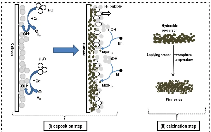
Literature survey shows that cathodic electrochemical deposition followed by calcination is one of the effective techniques for the large-scale production of nanostructured metal oxides [40-43], as schematically presented in Fig. 1.
Figure 1. Schematic outlook of metal oxide synthesis through cathodic electrochemical deposition-calcination procedure.
The mechanism of this facile two-step process can be written as [41,43]:
i- Electrodeposition step:
2H2O + 2e− → H2 + 2OH− Eo =−1.08 V vs. Ag/AgCl (1)
Mn+ (aq)+ nOH−(aq) + yH2O → M(OH)n .yH2O (2)
[image:2.596.118.479.339.564.2]
Here, metal hydroxide precursor is first deposited on the cathode electrode through electrochemical step. Next, the final oxide is achieved through calcination procedure by applying the proper atmosphere for the some hours. The pulse current mode can be applied in the base electrogeneration procedure of hydroxide precursor deposition. It has been reported that various morphologies of hydroxide precursor can be prepared under pulsed base conditions [19-21, 44-46]. Despite these clear advantages, this mode has been not used in the electrosynthesis of nickel oxide until now. This paper describes the facile preparation of NiO nano-rods/plates through pulsed base cathodic generation followed by calcination at 400oC for 2 hours. The supercapacitive performance of the prepared nanorods/nanoplates were assessed using cyclic voltammetry (CV) and charge-discharge tests. The results confirmed their excellent supercapacitive performance.
2. EXPERIMENTAL PROCEDURE
2.1. Reagents
Ni(NO3)2 .6H2O (Merck), polytetrafluoroethylene (PTFE, Merck), acetylene black and KOH
(Merck) were used as were used as received. All solutions were prepared using purified water by UHQ Elga System. Aqueous solution of 5 mM Ni(NO3)2 .6H2O was prepared for electrodeposition.
2.2. Synthesis procedure
For preparation of nickel oxide, the hydroxide precursor was first synthesized through the cathodic electrochemical deposition method. In this way, 1.45g of nickel nitrate was dissolved in 1L distilled water and used as the bath composition. The concentration of electrolyte bath was 0.005M Ni(NO3)2 .6H2O. The electrochemical cell was designed in a two electrode system including
stainless-steel sheet (316L with size of 10cm*10cm) centered between two parallel graphite anodes. Prior to each deposition, the steel cathode was exposed under an anodic electropolishing treatment [26]. The electrosynthesis process was ran in the pulse regime in the designed two-electrode system. Deposition experiments were conducted at the pulse current mode with applying the pulse parameters of (i) ton=50ms, (ii) toff=50ms, (iii) ipeak=0.002 A cm-2 and (iv) deposition time= 1h. The bath temperature
was fixed at 40 oC. Next the deposition step, the steel electrode was bring out from the electrolyte and washed several times with deionized water. At the end, the deposited green thin film was scrap from the surface of steel sheet and dried at RT for 48h. The obtained green powder was named as hydroxide precursor. The hydroxide powder was calcined at 400 oC for 2h inside a programmable furan under the air atmosphere. The obtained black powder was named as the oxide sample.
2.3. Instrumentation
from room temperature to 600 °C with a heating rate of 5 °C min–1 by a thermoanalyzer (STA-1500). The plate morphology of the prepared NiO sample was observed using a scanning electron microscope (SEM, LEO 1455VP). Cyclic voltammetry (CV) and galvanostatic charge–discharge (GCD) tests were done by an Autolab workstation system (AUTOLAB®, Eco Chemie, PGSTAT 30). The surface area of the synthesized NiO plates were measured through Brunauer−Emmett−Teller (BET) using quanta-chromeNOVA-2200e surface area analyzer.
2.3. Electrochemical measurements
A working electrode (i.e. supercapacitor electrode) was fabricated using the prepared NiO nanoplates, and their charge storage abilities were evaluated by CV and constant current charge and discharge tests in a three-electrode system. The working electrode was constructed through mixing the synthesized NiO, graphite and polytetrafluoroethylene (PTFE) binder (with the weight ratios of 85:10:5, respectively). The ready mixture was pressed, under 10 MPa, into nickel foam current collectors (1 cm × 1 cm) and then dried in oven for 15 min at 60 o
C. The CV and GCD tests were performed in a three compartment cell. The fabricated NiO electrode was used as the working electrode in this cell. A platinum plate (1 cm2) counter electrode and a An Ag/AgCl (1 M KCl, saturated) as the reference electrode were applied. 1 M KOH aqueous solution was used as an electrolyte. CV tests were done between −0.2 and 0.6 V (vs. Ag/AgCl) at the scan rates of 2, 5, 10, 25, 50, 75 and 100 mV/s. The specific capacitances (SCs) of the NiO working electrode was calculated from the following equation:
where C is the SC of NiO (F g–1), Va is the cut of value of anodic section, Vc is the cut of
cathodic potential, m is the mass of NiO used in the fabricated electrode (g), v is the scan rate (V s–1) and I(V) is a current response during the scan of potential. The mass loading of active materials was 2.1 mg. GCD tests were also performed in the potential range of −0.2 to 0.6 V (vs. Ag/AgCl) at the various current loads of 1, 2, 3, 5, 7 and 10 A g–1. The SCs of the NiO nanoplates were calculated from the GCD profiles using Eq. (5):
where C is the calculated SC for NiO electrode, I is the applied current load (A), ΔV is the potential window (0.8 V), Δt is the time of a discharge cycle (s) and m is the mass of NiO (g).
3. RESULTS AND DISCUSSION
3.1. Hydroxide formation
The Ni(OH)2 precursor was deposited on the steel surface by cathodic electrosynthesis. The
[33,34]. Briefly, water molecules are reduced on the cathode surface and hydroxyl ions produced. Notably, H2 bubbling during the deposition experiment and also the potential value (0.97 V vs.
Ag/AgCl) confirmed this fact. The nickel cations migrate toward the cathode surface and react with OH- ions to form the hydroxide deposit, as shown in Fig. 1. In which a green thin film is formed on the steel surface at the end of deposition experiment.
3.2. Heat-treatment mechanism
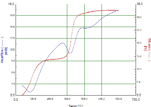
[image:5.596.169.425.281.463.2]Nickel oxide was prepared via calcination of the electro-synthesized hydroxide at 400oC for 2h. The physico-chemical changes during calcination were studied by DTA analysis, which presented in Fig. 2.
Figure 2. Thermogravimetric analysis (DSC and related TG curves) of the deposited nickel hydroxide precursor in dry air atmosphere and the temperature range of 25-600 oC.
The DSC curve of NiO nanoplates exhibit three main endothermic peaks at the applied calcination temperature range of 25-600 oC. These peaks are located at the temperature ranges of (a) 25-150 oC, (b) 150-350 oC, (c) 350-600 oC. Correspondingly, TG profile of hydroxide precursor has the distinct weight losses of 12.4, 18.5 and 1.1%as these temperature regions, respectively. The first temperature range (i.e. section a) is related to the removal of water incorporated into the deposited hydroxide:
[Ni(OH)2-x(NO3)x ·zH2O] → [Ni(OH)2-x(NO3)x] + zH2O (6)
The weight loss of 12.4 wt% is seen on TG profile for this event. The second endothermic peak on DSC curve can be assigned to the removal of structural water from the nickel hydroxide precursor, as shown below [32-34]:
This step has weigh loss of 18.5 wt%, which is very close to the theoretically expected value (i.e., 19.49 wt.% for the removal of one H2O molecule from Ni(OH)2). The last broad endothermic
peak at 350-600°C peak is related to the removal of nitrate from the deposit structure; Ni(NO3)x → NiO + x NO2 + x/2O2 (8)
Here, a weight loss of 1.1wt% is seen on the TG curve. At the end of calcination step, a black NiO powder was obtained, as confirmed by XRD and IR data.
3.3. Structural and morphological characterization
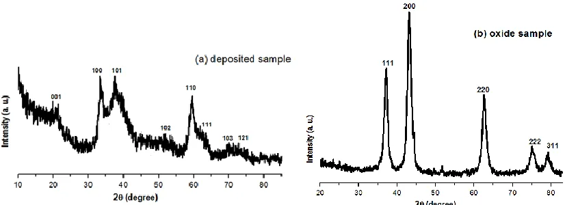
Fig. 3 shows the XRD patterns of our samples obtained throughout the electrosynthesis and calcination processes, including the hydroxide precursor and final oxide. All peaks in Fig. 3a correspond to the crystal planes of (001), (100), (101), (102), (110), (111), (103) and (121), which confirm the successful electrodeposition of Ni(OH)2 as the precursor (JCPDS 74-2075). The pattern is
purely consist with beta phase of nickel hydroxide and there is no any diffraction related to the alpha phase. After the precursor sample was calcined at 400 °C, the conversion from Ni(OH)2 to NiO
appears complete, since all diffraction peaks in Fig. 3b can be indexed to cubic NiO (JCPDS card no. 47-1049). No peaks from Ni(OH)2 are observed, indicating that Ni(OH)2 is completely converted to
NiO after calcination at 400 °C for 2h.
Figure 3. XRD patterns of (a) the electrodeposited nickel hydroxide precursor and (b) heat-treated nickel oxide product.
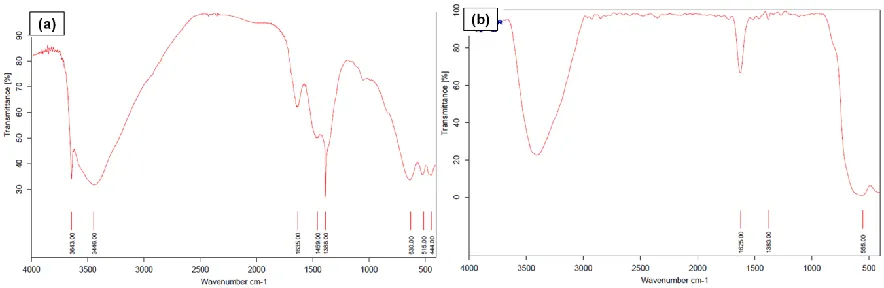
The FTIR spectra of the prepared samples are presented in Fig. 4. The spectra of the electro-synthesized precursor in Fig. 4a has all IR bonds related to the beta phase of nickel hydroxide. In this regards, (i) a narrow band at 3643 cm–1 is due to the ν(OH) stretching vibration of free OH groups; (ii) a band at 515 cm–1 corresponds to the hydroxyl groups’ lattice vibration, (iii) the broad bands around 3360 cm─1 and 1629 cm─1, because of the ν(H2O) stretching vibration and the δ(H2O) bending
[image:6.596.91.504.399.549.2]
vibrations of nitrate ions intercalated in the hydroxide structure [15-18,34]. These data clearly indicate the preparation of the β-Ni(OH)2 precursor from electrosynthesis procedure. Fig. 4b displays the FT-IR
[image:7.596.78.520.199.343.2]transmission spectra of the NiO sample. The peak at 555 cm−1 exhibits Ni–O stretching vibration and is evidence about the presence of the crystalline NiO. The absence of vibration peaks at 3643 cm–1 and 1388 cm−1 are clearly implicated the complete conversion of hydroxide to oxide, and nitrate removal from the hydroxide structure after calcination, respectively.
Figure 4. IR spectra of (a) the electrodeposited nickel hydroxide precursor and (b) heat-treated nickel oxide product.
Morphology of the prepared samples is presented in Fig. 5. It can be seen that both electrodeposited hydroxide and calcined oxide samples have a similar morphology. This observation implicates that the calcination procedure had no essential effect on the morphology on the electrodeposited hydroxide precursor. For both samples, two-type texture i.e. plate and rod is seen in the SEM images in Figs. 5(a-d). In fact, these two type of structures are equally coexisted in these images. These observations imply that plates and rods of hydroxide have been equally formed during the electrodeposition process. The hydroxide and oxide plates and rods have nano-size, discrete and free-standing form, which can embody the prepared samples to have high surface area (as confirmed via BET analysis in Fig. 6). These observations confirmed the preparation of NiO nano-rods/plates through our applied method.
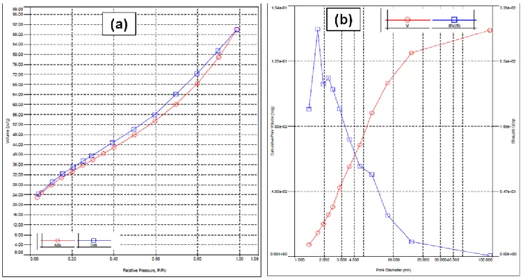
The N2 desorption-adsorption curve and the corresponding BJH (Barret–Joyner–Halenda) pore
size distribution profile of the NiO sample are presented in Fig. 6. The N2 isotherm of Co3O4
[image:8.596.102.498.70.414.2]
Figure 5. SEM images of (a,b) electrodeposited nickel hydroxide precursor and (c,d) final nickel oxide.
Figure 6. BET surface area of the prepared NiO sample; (a) N2 adsorption-desorption isotherm and (b)
[image:8.596.103.479.472.673.2]
In this way, amore efficient interaction between electrolyte and NiO electrode will be provided a better transferring of electrons and ions (i.e. fast redox reactions), which probably causes high energy storage ability.
3.5. Supercapacitive evaluation
The charge storage ability of the electrode fabricated from nickel oxide nano-rods/plates was investigated by cyclic voltammetry (CV) and galvanostat charge-discharge (GCD) electrochemical techniques.
[image:9.596.88.508.250.413.2]
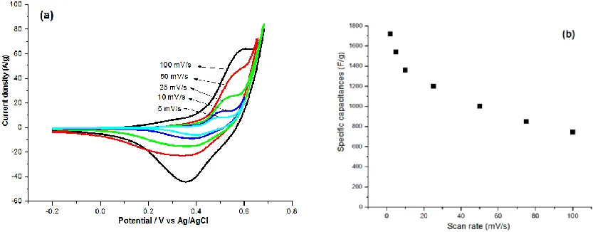
Figure 7. (a) CVs of the fabricated NiO electrode in 1M KOH at the different scan rates of 5, 10, 25, 50 and 100 mV/s and (b) the calculated specific capacitances at these applied scan rates.
Fig. 7a shows the CV profiles of the fabricated NiO working electrode in 1M KOH at the different scan rates. There is one pair redox peak in this the CV profiles, which is related to the Ni2+/Ni3+ redox reactions [33,34]. Furthermore, there is a double layer storage behavior at the potential range of -0.2 to ~+0.2V. In fact, as clearly seen CV profiles, the fabricated NiO electrode exhibits two different charge storage abilities i.e. (i) the electrical double-layer behavior at the potentials of -0.2 up to 0.2, and (ii) faradic based charge storage for potentials of 0.2 to 0.65V. Overlay, our fabricated electrode exhibits the pseudo-capacitance behavior which is different from the pure double layer capacitors. The mechanism of charging/discharging of NiO electrode i.e. its faradic reactions in aqueous KOH media has been previously discussed in detail [33,34]. Briefly, because of nickel oxide instability in the aqueous solution, a hydroxide layer is firstly formed at NiO surface:
NiO + H2O → Ni(OH)2 (at the surface of NiO) (9)
Then, the hydroxide/oxyhydroxide faradic reaction is proceeded in the KOH electrolyte: Ni(OH)2 + OH─ ↔ NiOOH + H2O + e─ (10)
Ni(OH)2—H+ → NiOOH + e─ (11)
Generally, the charge storage mechanism of the NiO nanoplates can be shown as [31,36]: NiO + zOH─ ↔ zNiOOH + (1-z) NiO +ze─ (12)
[image:10.596.82.506.381.704.2]by Eq. (4), the specific capacitances of NiO nanoplates were calculated to be 1720, 1541, 1365, 1172, 1006, 853 and 740 F g–1 at the scan rates of 2, 5, 10, 25, 50, 75 and 100 mV s–1, respectively (Fig. 7b). The values showed excellent supercapacitive performance of the prepared NiO electrode, which is related to the rod/plate morphology and high surface are of the fabricated electrode. Remarkably, the synthesized nanostructures have some deficiency in the pseudo-capacitances higher scan rates, where the calculated SCs are suddenly reduced by increasing the scan rate. Such performance lack has been previously observed for pure NiO nanostructures too [29-35,49]. This can be attributed to a low accessibility of the electro-active materials at the high scan rates in comparison with low ones [34,49]. In higher scan rates, the outer regions or surfaces of the oxide rods/plates are accessible and ionic diffusion occurs only on their surface region, whereas at low scan rate, both inner and outer surfaces of rods/plates get involved in the charge storage. Nevertheless, because of the lack of internal porosity in the prepared electrode, the impact of the inner materials is decreased at the higher scan rates. Therefore, the calculated specific capacitances at the higher scan rates are slightly reduced.
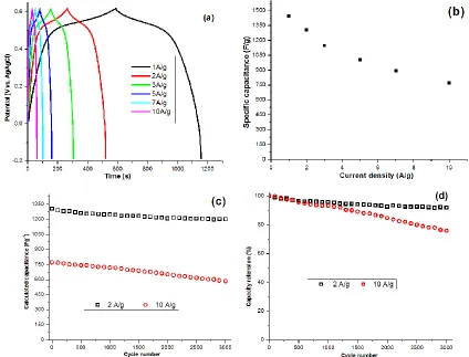
The GCD tests for the fabricated oxide electrode were performed at the different current loads of 1, 2, 3, 5 and 10 A g─1, and the results are presented in Fig. 8a. All GCD profiles have triangular forms implicating the good pseudo-capacitive performance of the fabricated nanomaterials. The SCs of the fabricated working electrode was calculated using Eq. (5) and the results are shown in Fig. 8b. The calculations gives the SCs as high as 1445 F g−1, 1307 F g−1, 1147 F g−1, 1006 F g−1, 892 F g−1 and 772 F g−1 at the applied current load of 1, 2, 3, 5, 7 and 10 A g−1, respectively. The values also approved the outstanding supercapacitive behaviour of the NiO nano-rods/plates. These SCs performances are comparable with those of NiO electrodes reported in Refs. [29-36,48].
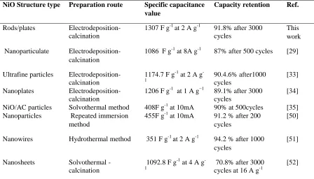
[image:11.596.75.523.503.759.2]The cycling ability i.e. SC value and capacity retention of the fabricated NiO electrode was also evaluated during 3000 continuous cycles at the current load of 2 and 10 A/g. The results are presented in Fig. 8c,d. The delivered capacity by NiO electrode for each cycle was calculated using Eq. (5), and the capacity retention of electrode was then evaluated based on the obtained SC for each cycle. Fig. 8c shows the cycling performance of the NiO electrode during 3000 cycles at the discharge current densities of 2 A g−1and 10 A g−1. The SCs of our electrode is reduced from 1307 F g−1 to 1201 F g−1 for the current load of 2 A g−1, showing a 91.8% capacity retention after 3000 cycling. Also, our NiO electrode exhibits the SC value of 558.7 F g−1 after 3000 cycling at 10 A g−1 A/g, revealing ~75.9% capacity retention (Fig. 8d). The results showed that the fabricated nano-rods/plates have highly stable charge storage ability during 3000 cycling and so can be suitable for long-time supercapacitor applications. The capacitance data (i.e. SC value and retention) of the fabricated NiO in this work and that of reported in literature are also listed in Table 1. From comparing the data, it can be seen that our prepared electrode has comparable supercapacitive performance, especially excellent performance in the cycle life.
Table 1. Comparison of the specific capacitance of NiO materials prepared in this paper and published in the literature
NiO Structure type Preparation route Specific capacitance value
Capacity retention Ref.
Rods/plates Electrodeposition-calcination
1307 F g-1 at 2 A g-1 91.8% after 3000 cycles
This work
Nanoparticulate Electrodeposition- calcination
1086 F g-1 at 8A g-1 87% after 500 cycles [29]
Ultrafine particles Electrodeposition-calcination
1174.7 F g-1 at 2 A g -1
90.4.6% after1000 cycles
[33]
Nanoplates Electrodeposition-calcination
1206 F g-1 at 1 A g−1 89.1% after 3000 cycles
[34]
NiO/AC particles Solvothermal method 408F g-1 at 10mA 90% at 500cycles [35] Nanoparticles Repeated immersion
method
455F g-1 at 10mA 91.2 % after 200 cycles
[50]
Nanowires Hydrothermal method 351 F g-1 at 2 A g-1 94.2 % after 1000 cycles
[51]
Nanosheets Solvothermal -calcination
1092.8 F g-1 at 4 A g -1
70.8% after 3000 cycles at 16 A g-1
Nanoflakes Hydrothermal 381 F g-1 at 2 A g-1 89.2% after 1000 cycles [53] Mesoporous nanotubes Sacrificial template strategy
790 F g-1 at 4 A g-1 94% after 2000 cycles [54]
Nanoflakes Potentiodynamical deposition
222 F g-1 at 0.1 mA/cm2
94% after 1000 cycles [55]
Porous nanofibers Electrospinning - calcination
737 F g−1 at 2A g−1 98% after 8000 cycles [56]
Mesoporous nanosheets
Solvothermal -calcination
945 F g−1at a 10 A g−1
92% after 500cycles [57]
ultrafine nanowires Hydrothermal method 1349 F g−1 at 5 A g−1 87% after 2000 cycles [58]
Microflowers Calcination of coordination microflowers
1678.4 F g−1 at 0.625 A g−1
99.7% after 1000 cycles
[59]
Hollow microspheres
Hydrothermal process 619 F g−1 at 5 mA cm−2
95% after 1000 cycles [60]
4. CONCLUSION
Nickel hydroxide was prepared through pulse cathodic electrodeposition from nickel nitrate solution. The characterization by XRD, IR and SEM revealed that the hydroxide precursor is composed of β-Ni(OH)2 with rod-plate morphology at nanoscale. Calcination of the deposited
hydroxide resulted the pure NiO nano-rods/plates, as confirmed by XRD, IR and SEM analyses. The supercapacitive performance of the prepared NiO nano-rods/plates was investigated by techniques of cyclic voltammetry (CV) and galvanostatic chargedischarge (GCD) within the potential window of -0.2 to 0.6V in 1 M KOH electrolyte. The measurements showed that the NiO electrode deliver high specific capacitance (1541 F g–1 at the scan rate of 5 mV s–1) and excellent capacity retention of 91.8% after 3000 cycling at the current load of 2 A g–1.
References
1. M. Jayalakshmi, and K. Balasubramania, Int. J. Electrochem. Sci. 3 (2008) 1196.
2. J. S. Shayeh, A. Ehsani, M. R. Ganjali, P. Norouzi, and B. Jaleh, Applied Surface Science 353 (2015) 594.
3. H. Gholipour-Ranjbar, M. R. Ganjali, P. Norouzi and H. R. Naderi, Mater. Res. Express 3 (2016) 075501.
4. H. R. Naderi, P. Norouzi, M. R. Ganjali and H. Gholipour-Ranjbar, Powder Technol. 302 (2016) 298.
5. J. Tizfahm, M. Aghazadeh, M. Ghannadi Maragheh, M.R. Ganjali, P. Norouzi, and F. Faridbod, Mater. Lett. 167 (2016) 153.
6. M. Aghazadeh, M. Asadi, M. Ghannadi Maragheh, M.R. Ganjali, P. Norouzi, and F. Faridbod, Appl. Surf. Sci. 364 (2016) 726.
7. H. R. Naderi, M. R. Ganjali, and P. Norouzi, Int. J. Electrochem. Sci. 11 (2016) 4267.
8. M. Aghazadeh, M. Ghannadi Maragheh, M.R. Ganjali, P. Norouzi, and F. Faridbod, Appl. Surf. Sci. 364 (2016) 141.
10.M. Aghazadeh, M. Ghannadi Maragheh, M.R. Ganjali, P. Norouzi, D. Gharailou, and F. Faridbod, J. Mater. Sci.: Mater. Electron. 27 (2016) 7707.
11.H. Gholipour-Ranjbar, M. R. Ganjali, P. Norouzi and H. R. Naderi, J. Mater. Sci. Mater. Electron. 27 (2016) 10163.
12.M. Aghazadeh, A. Bahrami-Samani, D. Gharailou, M. Ghannadi Maragheh, M.R. Ganjali, and P. Norouzi, J. Mater. Sci.: Mater. Electron. 27 (2016) 1.
13.M. Aghazadeh, M. Ghannadi Maragheh, M.R. Ganjali, and P. Norouzi, RSC Adv. 6 (2016) 10442. 14.W. Sun, X. Rui, M. Ulaganathan, S. Madhavi, and Q. Yan, J. Power Sources 295 (2015) 323. 15.M. Aghazadeh, A.N. Golikand, and M. Ghaemi, Int. J. Hydrogen Energy 36 (2011) 8674.
16.M. Aghazadeh, M. Ghaemi, B. Sabour, and S. Dalvand, J. Solid State Electrochem. 18 (2014) 1569. 17.M. Aghazadeh, B. Sabour, M.R. Ganjali, and S. Dalvand, Appl. Surf. Sci. 313 (2014) 581.
18.J. Tizfahm, B. Safibonab, M. Aghazadeh, A. Majdabadi, B. Sabour, and S. Dalvand, Colloids Surf. A 443 (2014) 544.
19.M. Aghazadeh, S. Dalvand, and M. Hosseinifard, Ceram. Int. 40 (2014) 3485.
20.M. Aghazadeh, A.-A. Malek Barmi, D. Gharailou, M.H. Peyrovi, B. Sabour, and F. Najafi Khosroshahi, Appl. Surf. Sci. 283 (2013) 871.
21.M. Aghazadeh, and S. Dalvand, J. Electrochem. Soc. 161 (2012) D18.
22.M. Aghazadeh, R. Ahmadi, D. Gharailou, M.R. Ganjali, and P. Norouzi, J. Mater. Sci.: Mater. Electron. 27 (2016) 8623.
23.J.T. Mehrabad, M. Aghazadeh, M.G. Maragheh, M.R. Ganjali, and P. Norouzi, Mater. Lett. 184 (2016) 223.
24.P. Razmjoo, B. Sabour, S. Dalvand, M. Aghazadeh, and M.R. Ganjali, J. Electrochem. Soc. 161 (2014) D293.
25.M. Aghazadeh, M. Hosseinifard, B. Sabour, and S. Dalvand, Appl. Surf. Sci. 287 (2013) 187. 26.M. Aghazadeh, J. Appl. Electrochem. 42 (2012) 89.
27.H. Gholipour-Ranjbar, M.R. Ganjali, P. Norouzi, and H.R. Naderi, Ceram. Int. 42 (2016) 12097. 28.H. R. Naderi, M. R. Ganjali, A. S. Dezfuli and P. Norouzi, RSC Advances 6 (2016) 51211. 29.H.Y. Wu, and H.W. Wang, Int. J. Electrochem. Sci. 7 (2012) 4405.
30.H. Xiao, S. Yao, H. Liu, F. Qu, X. Zhang and X. Wu, Progress in Natural Science: Mater. Int. 26 (2016) 271.
31.L. Junqing, S. Jingli, Y. Xi, Z. Xiaoling, T. Zechao, G. Quangui, and L. Lang, Int. J. Electrochem. Sci. 7 (2012) 2214.
32.H. Mohammad Shiri, and M. Aghazadeh, J. Electrochem. Soc. 159 (2012) E132.
33.A. Barani, M. Aghazadeh, M.R. Ganjali, B. Sabour, A.A. Malek Barmi, and S. Dalvand, Mater. Sci. Semicond. Process. 23 (2014) 85.
34.M. Aghazadeh, J. Mater. Sci.: Mater. Electron. (2016) accepted. 35.K. Wang, L. Li, and H. Zhang, Int. J. Electrochem. Sci. 8 (2013) 5036. 36.S. Wu, K.S. Hui, K.N. Hui, and K.H. Kim, J. Mater. Chem. A 4 (2016) 9113.
37.K. Adib, M. Rahimi-Nasrabadi, Z. Rezvani, S.M. Pourmortazavi, F. Ahmadi, H. R. Naderi, and M. R. Ganjali, J. Mater. Sci. 27 (2016) 4541.
38.B. Li, M. Zheng, H. Xue, and H. Pang, Inorg. Chem. Front. 3 (2016) 175.
39.M. Ranjbar, M.A. Taher, and A. Sam, J. Mater. Sci.: Mater. Electron. 26 (2015) 8029 40.M. Aghazadeh, M. Hosseinifard, Ceram. Int. 39 (2013) 4427.
41.F. Khosrow-pour, M. Aghazadeh, and B. Arhami, J. Electrochem. Soc. 160 (2013) D150. 42.M. Aghazadeh, A.A. Malek Barmi, H.M. Shiri, and S. Sedaghat, Ceram. Int. 39 (2013) 1045. 43.M. Aghazadeh, J. Electrochem. Soc. 159 (2012) E53.
44.F. Khosrow-pour, M. Aghazadeh, S. Dalvand, and B. Sabour, Mater. Lett. 104 (2013) 61. 45.I. Karimzadeh, M. Aghazadeh, B. Safibonab, M.R. Ganjali, and S. Dalvand, Russian J.
Electrochem. 51 (2015) 263.
47.F. Rouquerol, J. Rouquerol, K. Sing, Adsorption by powders and porous solids: principles, methodology and applications, Academic Press, San Diego, 1999.
48.S. Kumar Meher, P. Justin, and G. Ranga Rao, Nanoscale 3 (2011) 683.
49.K. Sathishkumar, N. Shanmugam, N. Kannadasan, S. Cholan, and G. Viruthagiri, J. Sol-Gel Sci. Technol. 74 (2015) 621.
50. K. Wang, L. Li, and H. Zhang, Int. J. Electrochem. Sci. 8 (2013) 4785.
51. Y.R. Ren, H.M. Wei, X.B. Huang, B. Yang, J.W. Wang, and J.N. Ding, Int. J. Electrochem. Sci. 9 (2014) 7206.
52.G. Huang, S. Xu, Y. Cheng, W. Zhang, J. Li, and X. Kang, Int. J. Electrochem. Sci. 10 (2015) 2594.
53.J. Zhao, H. Liu, and Q. Zhang, Appl. Surf. Sci. 392 (2017) 1097.
54.C. Yuan, L. Hou, Y. Feng, S. Xiong, and X. Zhang, Electrochim. Acta 88 (2013) 507.
55.A.D. Jagadale, V.S. Kumbhar, D.S. Dhawale, and C.D. Lokhande, J. Electroanal. Chem. 704 (2013) 90.
56.M. Kundu, and L. Liu, Mater. Lett. 144 (2015) 114.
57.M. Yao, Z. Hu, Y. Liu, P. Liu, Z. Ai, and O. Rudolf, J. Alloys Compd. 648 (2015) 414.
58.L. An, K. Xu, W. Li, Q. Liu, B. Li, R. Zou, Z. Chen, and J. Hu, J. Mater. Chem. A 2 (2014) 12799. 59.H. Pang, Y. Shi, J. Du, Y. Ma, G. Li, J. Chen, J. Zhang, H. Zheng, and B. Yuan, Electrochim. Acta
85 (2012) 256.
60. M. Fan, B. Ren, L. Yu, Q. Liu, J. Wang, D. Song, J. Liu, X. Jing, and L. Liu, Cryst. Eng. Comm. 16 (2014) 10389.