Iterative Joint Video and Channel Decoding in a Trellis-Based Vector-Quantized Video Codec
and Trellis-Coded Modulation Aided Wireless Videophone
R. G. Maunder, J. Kliewer, S. X. Ng, J. Wang, L-L. Yang and L. Hanzo
School of ECS, University of Southampton, SO17 1BJ, UK.
Email:
{
rm02r,jk03v,sxn,jw02r,lly,lh
}
@ecs.soton.ac.uk, http://www-mobile.ecs.soton.ac.uk
Abstract– We propose a Vector-Quantized (VQ) video codec that induces deliberately-introduced code constraints. The complete set of these code constraints are unambiguously described by a novel block-based modification of a symbol-block-based variable length coding trellis struc-ture. This trellis is employed during VQ encoding to represent video information with a Minimum Mean Squared Error (MMSE) recon-struction. Additionally, the proposed trellis structure is employed in the video decoder to obtaina posterioriprobability based MMSE estimates of the transmitted VQ tiles. Since the trellis structure unambiguously describes the code constraints induced by the video codec, its employ-ment guarantees the automatic recovery of valid sets of VQ tiles. The proposed video codec is serially concatenated with a trellis-coded modu-lation scheme for transmission over a fast-fading Rayleigh fading chan-nel. In the receiver, iterative-decoding convergence that eliminates all perceivable channel-induced video distortion is shown to be supported within 1.29 dB of the system’s 2 bit/s/Hz channel-capacity limit of 3.96 dB.
I. INTRODUCTION
The limited validity of Shannon’s source and channel coding separation theorem [1] for practical video transmission systems over realistic wideband fading mobile radio channels [2] motivates the application of joint source and channel coding techniques. One such technique is offered by the ex-tension of serially-concatenated iterative decoding [3] to exploit the resid-ual redundancy offered by the code constraints induced by a video codec. These code constraints are either deliberately induced during the design of the source codec or are inherently present, owing to low-complexity source codec design, for example. In such systems, the inner and outer iterative-decoding stages are comprised by the channel and the source decoder, re-spectively. Extrinsic information is exchanged between these iterative-de-coding stages, with each using a specific trellis-based description of the cor-responding code constraints.
Video codecs typically have an algorithmically-complex design due to their exploitation of the psycho-visual imperfections of human vision [2]. Hence, it is typically difficult to describe the complete specification of the code constraints induced by a video codec in a trellis form. Additionally, a serially-concatenated iterative-decoding aided system that aims for exploit-ing the residual redundancy resultexploit-ing from the code constraints of a typi-cal video codec may not support iterative-decoding convergence that elimi-nates all perceivable channel-induced video distortion. Thus, in [4], a trellis-based intermediate decoder comprised the outer iterative-decoding stage of a serially-concatenated video transmission system. Following the iterative recovery of the video-encoded bits, they were forwarded to a stand-alone video decoder for video reconstruction. Since the code constraints induced by the video codec were not exploited during the iterative-decoding process,
The financial support of the EPSRC, Swindon UK, the EU under the aus-pices of the NEWCOM, NEXWAY and Phoenix porojects and the Lever-hulme Trust, London UK is gratefully acknowledged.
the recovered video-encoded bits may not constitute a legitimate representa-tion of video informarepresenta-tion, resulting in reduced-quality video reconstrucrepresenta-tion.
Against this background, the concept of iterative joint video and chan-nel decoding is investigated in this contribution, where the outer iterative-decoding stage is constituted by a specifically designed trellis-based video decoder, rather than the intermediate decoder of [4]. In order to demonstrate the benefits of this principle, we propose the VQ-TCM system in Section II. Here, the inner and outer iterative-decoding stages are provided respectively by a Trellis-Coded Modulation codec and a block-based video codec, which employs both Vector Quantization (VQ) and Variable Length Coding (VLC). As it will be described in Section III, a novel block-based modification of the VLC-based symbol-level trellis structure of [5] is employed to unam-biguously describe the complete set of code constraints induced by the video codec. Using a similar philosophy to Trellis Coded Quantization (TCQ) [6], a novel employment of this trellis structure is invoked in the proposed video encoder to perform VQ, as it will be described in Section IV. Finally, a novel block-based modification of the The Bahl-Cocke-Jelinek-Raviv (BCJR) al-gorithm [7] is employed by the proposed video decoder, which also operates on the basis of the proposed trellis structure, as it will be described in Sec-tion V. In SecSec-tion VI, both low- and high-latency implementaSec-tions of the proposed VQ-TCM system are introduced and their video reconstruction quality is assessed. Additionally, the proposed VQ-TCM system’s iterative-decoding convergence performance is investigated with the aid of an EXtrin-sic Information Transfer (EXIT) chart analysis [8]. Finally, the performance of the proposed joint video and channel coding approach is compared to that of the bench marker of [4]. Our conclusions are offered in Section VII.
II. SYSTEM OVERVIEW
In this section, we introduce the proposed VQ-TCM system, which em-ploys a joint video and channel coding philosophy, as alluded to in Sec-tion I. The video codec employs an algorithmically-simple design, having only frame differencing and VQ components, with only the latter imposing code constraints on the video-encoded bits. We commence by describing the operation of frame differencing and iterative decoding, with the specifics of VQ encoding and decoding being saved for Sections IV and V, respectively.
TCM encoder
x
ˆfn−1
u1
uM
u1
uM
MVQ encoders
MVQ decoders Reconstruction
buffer fn
ˆfn
u π
−
+
+ +
e1
eM
e
ˆe ˆeM
[image:1.595.312.547.554.612.2]ˆe1
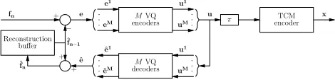
Fig. 1. The proposed VQ-TCM system’s transmitter.
In the proposed VQ-TCM system’s transmitter, shown in Figure 1, the Frame Difference (FD)e=fn−ˆfn−1is vector quantized for the sake of conveying the video information to the receiver. Each FDeis represented by a transmission frameu, as will be detailed in Section IV. The transmis-sion frameuis interleaved (π) and TCM-encoded, giving the channel-input symbolsx, as seen in Figure 1. As usual, a local decoder is employed to
obtain the VQ reconstructionˆeof the FDe. This classic local-decoding technique is employed to obtain the local reconstruction of the current video frameˆfn=ˆe+ˆfn−1, which becomes the frame-differencing reference for the next video frame.
π
MVQ BCJR decoders (2) L2
a(u1) L2a(uM)
L2p(u1) L2p(uM)
π−1
L2 e(u)
BCJR
(1) TCM
decoder y
Reconstruction buffer ˜fn−1
L1 a(u) =L2
e(u) L2
p(u) =L1 e(u) +L2
e(u) L1
e(u)
+ −
+
−
+ ˜fn
+ ˜e ˜e1
˜eM
L1
[image:2.595.62.298.110.201.2]p(u) =L2e(u) +L1e(u) L2a(u) =L1e(u)
Fig. 2. The proposed VQ-TCM system’s receiver.
A serially-concatenated iterative-decoding design is employed by the pro-posed VQ-TCM system’s receiver, as shown in Figure 2. As in [4], the inner iterative-decoding stage is constituted by a TCM decoder. However, the outer iterative-decoding stage of the proposed VQ-TCM system’s re-ceiver is constituted by the VQ decoder, rather than an intermediate de-coder as employed in [4]. Observe in Figure 2 that, during each decoding iteration, both iterative-decoding stages generatea posterioriLogarithmic Likelihood-Ratios (LLRs) [9]Lp(u)by applying their associated code con-straints to thea prioriLLRsLa(u)supplied by the other iterative-decoding stage and, in the case of the inner iterative-decoding stage, by the received channel-output symbolsy. Following each iterative-decoding stage, the subtraction ofLa(u)fromLp(u)is necessary for the sake of generating the extrinsic LLRsLe(u)(plus the information recovered fromyin the case of the inner iterative-decoding stage), which allows us to prevent the re-use of already-exploited information. It is the resultant extrinsic information that provides thea prioriinformation for the next iterative-decoding stage. De-interleaving (π−1) is applied toL1e(u)in order to generateL2a(u), whilst interleaving is applied toL2e(u)for the sake of producingL1a(u). Iterative decoding continues until convergence is achieved, as it will be detailed in the context of the EXIT chart analysis of Section VI. Following this, a soft FD reconstruction˜eis provided, as it will be highlighted in Section V. Finally, the reconstruction of the current video frame is obtained as˜fn=˜e+˜fn−1. As will be described in Sections IV and V respectively, VQ encoding and decoding is performed with the assistance of the novel trellis structure to be described in Section III-C. Owing to the specific nature of this trellis structure, its complexity is proportional to the square of the represented FD area. For this reason, each FDeand the corresponding transmission frame
uis divided intoMsub-frames, as will be described in Section III-A, with each encoded and decoded separately. These sub-frames are identified by the denotive superscriptm, wherem∈[1. . . M]is the sub-frame index, and the decompositions into sub-frames, as well as their recombinations, are represented by braces in Figures 1 and 2.
III. VQ-INDUCED CODE CONSTRAINTS
As stated in the previous section, each FDeis represented by a single transmission frameuin the proposed VQ-TCM system. This section out-lines the format of these transmission frames and describes the VQ-induced code constraints. These code constraints must be adhered to during VQ encoding and they deliberately introduce residual redundancy, without un-duly increasing the associated bitrate, which may be exploited during VQ decoding to assist the iterative-decoding process of the proposed VQ-TCM system’s receiver, as described in Section II. These code constraints are in-duced by the specific decomposition of each FDeinto FD sub-framesem and by the specific nature of the VQ codebook employed. Owing to the simple nature of the proposed video codec, the complete set of these code constraints may be represented using a novel trellis structure, which may be employed to assist VQ encoding and decoding. These issues are discussed
in the following sub-sections and are described with the aid of an example that is illustrated in Figures 3, 4 and 5.
III-A. Frame difference decomposition
As stated in Section II, the FDeis decomposed intoMFD sub-frames, with each FD sub-frameemrepresented by a separate transmission sub-frameum. This is explained with the aid of an example, which is provided in Figure 3.
9
10
11
12
4
1
2
3
5
6
7
8
Fig. 3. Example selection ofJ = 12 (8×8)-pixel video blocks from a
(48×48)-pixel FD to provide one ofM= 3FD sub-frames.
The VQ codec operates on a block-based philosophy, with thevideo block being defined as the smallest unit of video information considered in isola-tion and having dimensions of(8×8)pixels. As shown in Figure 3, each FD sub-frameemcomprises a unique combination ofJ(8×8)-pixel video blocks in disjointed groups from the FDe, whereecomprises(M·J)video blocks in total. A video-block indexj∈[1. . . J]is allocated to each of the
J(8×8)-pixel video blocks, denotedemj , in the FD sub-frameem, with consecutive indices being allocated within video-block groups.
The specifics of the FD decomposition are not detailed owing to space limitations. Suffice to say that each FD sub-frame has similar statistical properties and identical disjointed-group shapes and block-index allocations.
III-B. VQ codebook
Each FD sub-frameemis represented by the reconstructed FD sub-frame
ˆemand the transmission sub-frameumon the basis of VQ. Since, as stated in Section III-A, all FD sub-frames have similar statistical properties, iden-tical designs and a singleK-entry VQ codebook can be employed for the
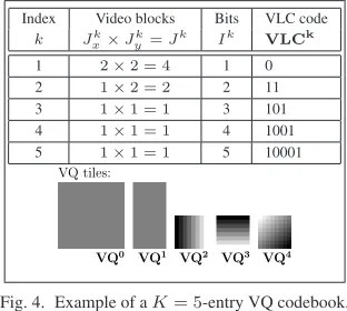
Mseparate VQ encoders and decoders. ThisK-entry VQ codebook com-prises the VQ tiles and their VLC-based representations known to both the transmitter and receiver. An example of aK = 5-entry VQ codebook is provided in Figure 4. In the VQ tiles of this figure, dark pixels indicate neg-ative frame-difference values, grey represents zero values and light pixels represent positive frame-difference values.
Index Video blocks Bits VLC code
k Jk
x×Jyk=Jk Ik VLCk
1 2×2 = 4 1 0
2 1×2 = 2 2 11
3 1×1 = 1 3 101
4 1×1 = 1 4 1001
5 1×1 = 1 5 10001
VQ0 VQ1 VQ3 VQ4
VQ tiles:
[image:2.595.351.507.512.652.2]VQ2
Fig. 4. Example of aK= 5-entry VQ codebook.
as shown in Figure 4.
Each reconstructed FD sub-frameˆemcomprisesJ(8×8)-pixel video blocks from the FDe. TheseJvideo blocks are provided by an appropriately-selected tessellation of VQ tiles from the employed VQ codebook. Each employment of the VQ tileVQkof the VQ codebook entry with indexk
provides the video blocks for a(Jxk×Jyk)-block region of the reconstructed FD sub-frameˆem. A constraint is imposed to allow the formation of the novel trellis structure described in the next sub-section. Specifically, the
Jk=Jxk·Jykvideo blocks ofˆemprovided by the employment ofVQk must have consecutive indices. This constraint therefore depends upon the employed decomposition of the FD into sub-frames, as described in Sec-tion III-A.
The transmission sub-frameumcomprises the concatenation of the VLC codes associated with the VQ tiles providing theJvideo blocks of the re-constructed FD sub-frameˆem. However, in the proposed video codec, each transmission sub-frame is constrained to having a length ofIbits. Since the VQ codebook entry having indexkrepresentsJkvideo blocks withIkbits, the task of finding an appropriateJ-block reconstructed FD sub-frameˆem and itsI-bit transmission sub-frameumis non-trivial. This motivates the use of a trellis structure.
III-C. VQ trellis structure
A trellis structure, comprising a set of transitions between trellis states, is employed by the proposed VQ encoder and decoder to represent the com-plete set of VQ-induced code constraints. A novel block-based modification of the symbol-level VLC trellis structure described in [5] is employed. Here, the VLC symbol axis of [5] is replaced by a video block axis. In contrast to [5], transitions are permitted encompass a number of consecutive positions along this axis.
The proposed VQ trellis structure allows the consideration of every valid combination of VQ codebook entries that provideJvideo blocks for the reconstructed FD sub-frameˆemandIbits for the transmission sub-frame
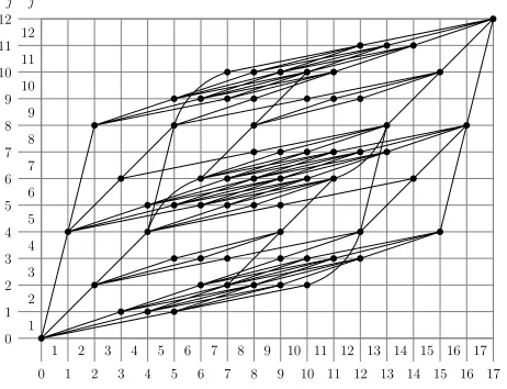
um. The specific structure of the proposed VQ trellis therefore depends on the VQ codebook employed. This structure also depends on the employed decomposition into sub-frames owing to the constraint described in Sec-tion III-A. The VQ trellis structure example of Figure 5 contains all valid transitions, and highlights the associated trellis states, corresponding to the
K = 5-entry VQ codebook of Figure 4 and the FD sub-frame of Figure 3 forJ= 12andI= 17.
0 1 2 8 13 14
1 2 3
3 4
4
5 6 7 8 9 10 11 12 13 14 15 16 17
5 6 7 9 10 11 12 15 16 17ı
i j
0 1
2 3 4 5 6 7 8 9 10 11 12
2 3 4 5 6 7 8 9 10 11 12
[image:3.595.63.294.493.670.2]1
Fig. 5. Example of a VQ trellis structure for the VQ codebook provided in Figure 4 and the example FD sub-frame provided in Figure 3, where we haveJ= 12andI= 17.
In Figure 5, the video-block and bit indices,j ∈ [1. . . J]andi ∈
[1. . . I]respectively, occur between the corresponding trellis state indices,
namely∈[0. . . J]for the video blocks andı∈[0. . . I]for the bits. Each trellis stateS,ırepresents the encoding progress made immediately after the consideration of the firstvideo blocks in theJ-block reconstructed FD sub-frameˆemand the firstıbits in theI-bit transmission sub-frameum, as illustrated in Figure 5. Each transitionT represents the employment of the VQ codebook entry with indexkTat a specific point during the FD sub-frame encoding process. This point is identified by the state indicesT and
ıT, with the transitionTembarking from the trellis stateST,ıT. As stated in Section III-B, the employment of the VQ codebook entry with indexkT
providesJkT(8×8)-pixel video blocks for the reconstructed FD sub-frame andIkT bits for the transmission sub-frame. This results in arriving at the trellis stateST+JkT,ıT+IkT immediately after the employment of the VQ codebook entry with indexkT.
The proposed VQ trellis structure contains all valid transition paths be-tween the trellis statesS0,0andSJ,I, as shown in Figure 5, and therefore represents the complete set of VQ-induced code constraints.
IV. VQ ENCODER
In the proposed VQ-TCM system’s transmitter shown in Figure 1 and described in Section II, the VQ encoding process is separately applied to all of theMFD sub-frames. Each VQ encoder operates on the basis of the proposed VQ trellis structure outlined in Section III-C, which is reminiscent of TCQ [6]. Here, we seek the optimal tessellation of the VQ codebook’s tiles, which have different dimensions, as described in Section III-B and are exemplified in Figure 4. The aim of this template-matching optimisation is to provide the Minimum Mean Squared Error (MMSE) reconstructionˆem of the FD sub-frameem.
Since the proposed VQ trellis structure represents the complete set of VQ-induced code constraints, its employment represents the consideration of every possible valid FD sub-frame encoding, allowing the most appropriate one to be selected. This is achieved using the philosophy of Viterbi decoding [10], with a survivor path being selected at each trellis stateS,ı. This selec-tion yields theı-bit encoding of the firstvideo blocks inemthat introduces the lowest possible distortionD(S,ı).
As stated in Section III-C, a transitionTin the proposed VQ trellis struc-ture, which is associated with the VQ codebook indexkT, corresponds to employing the VQ tileVQkTto represent a total ofJkT (8×8)-pixel video blocks of the FD sub-frameem. The distortion associated with the transitionT, namelyd(T), is the sum of the squared difference between
VQkT
and the correspondingJkT video blocks ofem.
The survivor path at the trellis stateS,ıis deemed to be that associated with the specific merging transitionThaving the minimum cumulative dis-tortionD(T) =d(T)+D(ST,ıT), where we haveD(S0,0) = 0. Having determined the survivor path at the trellis stateSJ,I, the optimum MMSE VQ encoding of the FD sub-frameemhas been found. The reconstructed FD sub-frameˆemis formed as the tessellation of the VQ tiles associated with the survivor path transitions and the transmission sub-frameum is formed as the concatenation of the associated VLC codes, as exemplified in Figure 4.
V. VQ BCJR DECODER
In the proposed VQ-TCM system’s receiver seen in Figure 2, BCJR de-coding is employed for all of theMFD sub-frames, as described in Sec-tion II. More specifically, each VQ BCJR decoder considers thea priori LLRsL2a(um), which pertain to the bits of the transmission sub-frameum, to generate thea posterioriLLRsL2p(um)and the reconstructed FD sub-frame˜em. This process employs the proposed VQ trellis to exploit the residual redundancy provided by the VQ-induced code constraints. Before describing the VQ BCJR decoder’s operation, we provide some additional background on the subject.
pro-vides a specific BCJR algorithm that gives soft symbol-level output. With the introduction of a normalisation factor, [11] extends this BCJR algorithm to additionally provide soft bit-level output, for the sake of facilitating itera-tive extrinsic information exchange. This is achieved following the calcula-tion of thea posterioritransition probabilities by considering a cross-section of the trellis that is perpendicular to the bit index axis and positioned at the bit of interest. Next, the bisected transitions are divided into two sub-sets according to the bit value they represent at their bisection. Finally, thea posterioriprobability of the bit of interest having a particular value is ar-ranged to be proportional to the sum of the appropriate sub-set’sa posteriori transition probabilities.
On the basis of the proposed VQ trellis structure of Section III-C, the BCJR technique of [11] is employed by each VQ BCJR decoder to provide a posterioribit probabilities, which are converted to thea posterioriLLRs
L2
p(um)[9]. This method was additionally adapted to providea posteriori video-block probabilities. During VQ encoding, each application of the VQ tileVQkis employed to represent a set ofJknumber of(8×8)-pixel video blocks of the FD sub-frameem. We seek thea posterioriprobability thatVQkuse employed by the VQ encoder for the representation of the video blockemj ofem. This probability is termedP(ˆemj ∈ VQk|y)
and, in analogy to thea posterioribit probabilities, is obtained by making a trellis cross-section perpendicular to the block axis and positioned at the video-block indexj.
TheA PosterioriProbability (APP)-based MMSE estimation of the rep-resentation of the video blockemj is obtained as
˜
emj =Kk=1P(ˆemj ∈VQk|y)·VQk j,
whereV Qkj, withj ∈ [1. . . Jk], is the particular(8×8)-pixel video block ofVQkthat may have been employed to representemj . Finally, the set of video blocks˜emj are tessellated to provide˜em. Since the proposed VQ trellis structure represents the complete set of VQ-induced code con-straints, its employment during VQ decoding guarantees the recovery of valid, although not necessarily correct, sets of VQ tiles.
VI. RESULTS
In this section, the achievable performance of the proposed VQ-TCM sys-tem is assessed using the 10 frame/s grey-scale head-and-shoulders(176× 144)-pixel Quarter Common Intermediate Format (QCIF) ’Lab’ video se-quence [2]. This video sese-quence exhibits a moderate level of video activity and was not included in the VQ training set, which comprised five 250-frame video sequences. Two VQ-TCM schemes were implemented using two dif-ferent interleaver lengths. The first scheme imposed a low latency equal to the duration of a single video frame (0.1 s at 10 frame/s), which is suitable for real-time interactive video-telephony applications. The second scheme had a high latency of 50 video frames (5 s at 10 frame/s), which is suitable for non-realtime video streaming and wireless internet download applica-tions. In the low-latency scheme, the length of each transmission frameu and that of the interleaverπequalsM·J= 1485bits. In the high-latency scheme, 50 transmission framesuare concatenated before interleaving, giv-ing a interleaver length of50·M·J = 74250bits. Both schemes have an encoded-video bitrate of 14.85 kbps. Having described the differences between the two schemes, we continue by discussing their common fea-tures. This section will be concluded by considering the performance of the different-latency schemes and comparing them to that of the bench marker scheme of [4].
In both schemes, each FD was divided intoM = 33FD sub-frames. Each FD sub-frame comprisedJ= 12 (8×8)-pixel video blocks and each transmission sub-frame consisted ofI = 45bits. AK = 512-entry VQ codebook was employed, comprising the five VQ tiles shown in Figure 4 and an additional 507 single-video-block VQ tiles, which were generated using the Linde-Buzo-Gray (LBG) algorithm [12]. The probability of occurrence of all VQ tiles was evaluated and the VQ codebook entries were assigned
Reversible VLC (RVLC) codes [13] having a minimum free-distance of 2. The coding rate of the RVLC-represented VQ codec isRV Q = 0.666, which is the ratio of its entropy to its actual average RVLC length. A ter-minatedRT CM = 3/4-rate TCM scheme employing a code memory of 6,MT CM = 16QAM modulation and IQ-interleaving [14] was employed for transmission over an uncorrelated narrowband Rayleigh fading chan-nel. The bandwidth efficiency of the proposed VQ-TCM system is given by
η=RV Q×RT CM×log2(MT CM) = 2.00bit/s/Hz, when ideal Nyquist filtering is assumed and the presence of the code termination symbols added by the TCM encoder is ignored. Note that atη= 2bit/s/Hz, the uncorre-lated Rayleigh-fading channel-capacity limit for 16QAM isEb/N0= 3.96
dB [15], whereEb/N0=SN R/ηis the Signal to Noise Ratio (SNR) per bit.
The EXIT characteristics of the TCM decoder operating at variousEb/N0
values are provided in Figure 6, along with the VQ decoder’s inverted EXIT characteristic. Employing RVLC codes with a minimum free-distance of 2 in the VQ codebook was found to yield a VQ decoder EXIT characteristic that achieves unity extrinsic mutual informationIE2 for unitya priori mu-tual informationIA2. Iterative-decoding convergence at unity mutual infor-mation, which is associated with the elimination of all perceivable channel-induced video distortion, is therefore supported. A ‘tunnel’ between the TCM and inverted VQ EXIT characteristics, giving iterative-decoding con-vergence at unity mutual information, can be seen forEb/N0 >5.25dB in Figure 6, which is just 1.29 dB away from the proposed VQ-TCM sys-tem’s 2 bit/s/Hz channel-capacity limit of 3.96 dB. The EXIT trajectories are provided for both the low- and high-latency schemes atEb/N0= 6dB, with the latter closely matching the VQ and TCM EXIT characteristics and achieving the desired unity mutual information. By contrast, the low-latency scheme deviates from these EXIT characteristics and fails to converge to the desired unity mutual information limit atEb/N0 = 6dB. The improved performance of the high-latency scheme is explained by its employment of a longer interleaver length [9].
0.0 0.1 0.2 0.3 0.4 0.5 0.6 0.7 0.8 0.9 1.0
IA
1, IE
20.0 0.1 0.2 0.3 0.4 0.5 0.6 0.7 0.8 0.9 1.0
I
E 1,I
A
2
High latency Eb/N0= 6 dB
Low latency Eb/N0= 6 dB
EXIT trajectory: Eb/N0= 11 dB
Eb/N0= 10 dB
Eb/N0= 9 dB
Eb/N0= 8 dB
Eb/N0= 7 dB
Eb/N0= 6 dB
Eb/N0= 5.25 dB
Eb/N0= 4 dB
[image:4.595.337.520.428.608.2]TCM EXIT characteristic: Inverted VQ EXIT characteristic
Fig. 6. The proposed VQ-TCM system’s EXIT chart [8] for the ‘Lab’ video sequence and a3/4-rate TCM scheme.
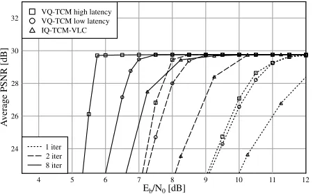
aesthetically pleasing reconstruction which contains only a negligible level of channel-induced distortion. The high-latency scheme can be seen to out-perform the low-latency scheme, regardless of the number of decoding iter-ations, as predicted by our EXIT chart analysis. In Figure 7, a PSNR value higher than 29.5 dB can be seen to be achieved by both the low- and high-latency schemes after eight decoding iterations forEb/N0 >7.00dB and
Eb/N0= 5.75dB, respectively.
4 5 6 7 8 9 10 11 12
Eb/N0[dB]
24 26 28 30 32
A
verage
PSNR
[dB]
IQ-TCM-VLC VQ-TCM low latency VQ-TCM high latency
[image:5.595.71.296.152.292.2]8 iter 2 iter 1 iter
Fig. 7. PSNR performance of the proposed VQ-TCM system and the IQ-TCM-VLC bench marker for the ‘Lab’ video sequence when communi-cating over an uncorrelated narrowband Rayleigh fading channel.
The IQ-TCM-VLC system of [4] has a single-video-frame latency and a similar coding rate, bitrate and error-free reconstruction quality to those of the proposed VQ-TCM system. The PSNR performance of the IQ-TCM-VLC system of [4], which is also shown in Figure 7, was found to be im-proved by the low-latency VQ-TCM scheme, regardless of the number of decoding iterations. At a PSNR of 29.5 dB, this improvement was approxi-mately 1.5 dB, again, regardless of the number of decoding iterations. The observed poorer performance of the IQ-TCM-VLC system [4] may be ex-plained by its employment of an intermediate decoder. Since this intermedi-ate decoder is unable to assess the validity of the recovered video-encoded bits, channel-induced-error masking may be required, when error-free re-covery is not achieved. This may inflict significant channel-induced distor-tion upon the reconstructed video sequence.
VII. CONCLUSIONS
In this contribution, the joint video and channel coding based VQ-TCM transmission system has been proposed. The outer iterative-decoding stage of this serially-concatenated video transmission system was constituted by the proposed trellis-based video decoder, rather than an intermediate de-coder as was the case in [4]. By adopting an algorithmically-simple design it was possible to unambiguously describe the video-codec-induced code con-straints by a novel trellis structure, which was employed to perform MMSE VQ encoding. A modified BCJR algorithm utilising the novel trellis struc-ture was employed to obtain soft APP-based block-level outputs. These were employed to calculate a MMSE estimation of the video-encoded in-formation. Since the novel trellis structure represented the complete set of VQ-induced code constraints, its employment guaranteed the recovery of valid sets of VQ tiles, eliminating the need for error masking during video reconstruction, which was required in [4]. In the proposed VQ-TCM sys-tem’s receiver, iterative-decoding convergence that eliminates all perceiv-able channel-induced video distortion was shown to be supported within 1.29 dB of the system’s 2 bit/s/Hz channel-capacity limit of 3.96 dB. Fi-nally, the proposed VQ-TCM system was shown to outperform the bench marker system of [4], which employed an intermediate decoder, rather than the video decoder, to exchange extrinsic information with the inner iterative-decoding stage.
VIII. REFERENCES
[1] C. E. Shannon, “A Mathematical Theory of Communication,”The Bell System Technical Journal, vol. 27, pp. 379–656, July 1948.
[2] L. Hanzo, P. J. Cherriman and J. Street,Wireless Video Communica-tions: Second to Third Generation Systems and Beyond. New York, USA: IEEE Press, 2001.
[3] S. Benedetto, D. Divsalar, G. Montorsi and F. Pollara, “Serial Concate-nation of Interleaved Codes: Performance Analysis, Design and Iter-ative Decoding,”IEEE Transactions on Information Theory, vol. 44, pp. 909–926, May 1998.
[4] S. X. Ng, R. G. Maunder, J. Wang, L-L. Yang and L. Hanzo, “Joint Iterative-Detection of Reversible Variable-Length Coded Constant Bit Rate Vector-Quantized Video and Coded Modulation,” in Euro-pean Signal Processing Conference (EUSIPCO), (Vienna, Austria), pp. 2231–2234, September 2004.
[5] R. Bauer and J. Hagenauer, “Symbol-by-Symbol MAP Decoding of Variable Length Codes,” inITG Conference on Source and Channel Coding, (Munich, Germany), pp. 111–116, January 2000.
[6] M. W. Marcellin and T. R. Fischer, “Trellis Coded Quantization of Memoryless and Gauss-Markov Sources,”IEEE Transactions on Communications, vol. 38, pp. 82–93, January 1990.
[7] L. R. Bahl, J. Cocke, F. Jelinek and J. Raviv, “Optimal Decoding of Linear Codes for Minimizing Symbol Error Rate,”IEEE Transactions on Information Theory, vol. 20, pp. 284–287, March 1974.
[8] S. ten Brink, “Convergence Behaviour of Iteratively Decoded Par-allel Concatenated Codes,”IEEE Transactions on Communications, vol. 49, pp. 1727–1737, October 2001.
[9] J. Hagenauer, E. Offer and L. Papke, “Iterative Decoding of Binary Block and Convolutional Codes,”IEEE Transactions on Information Theory, vol. 42, pp. 429–445, March 1996.
[10] L. Hanzo, T. H. Liew and B. L. Yeap,Turbo Coding, Turbo Equalisa-tion and Space Time Coding for Transmission over Wireless Channels. Chichester, UK: Wiley, 2002.
[11] J. Kliewer and R. Thobaben, “Iterative Joint Source-Channel Decod-ing of Variable-Length Codes UsDecod-ing Residual Source Redundancy,” IEEE Transactions on Wireless Communications, vol. 4, May 2005. [12] Y. Linde, A. Buzo and R. Gray, “An Algorithm for Vector Quantizer
Design,”IEEE Transactions on Communications, vol. 28, pp. 84–95, January 1980.
[13] Y. Takishima, M. Wada and H. Murakami, “Reversible Variable Length Codes,” IEEE Transactions on Communications, vol. 43, pp. 158–162, Feb/Mar/Apr 1995.
[14] S. X. Ng and L. Hanzo, “Space-Time IQ-Interleaved TCM and TTCM for AWGN and Rayleigh Fading Channels,”IEE Electronics Letters, vol. 38, pp. 1553–1555, November 2002.
![Fig. 6. The proposed VQ-TCM system’s EXIT chart [8] for the ‘Lab’ videosequence and a 3/4-rate TCM scheme.](https://thumb-us.123doks.com/thumbv2/123dok_us/8511987.350361/4.595.337.520.428.608/fig-proposed-tcm-exit-chart-lab-videosequence-scheme.webp)