This is a repository copy of
Fast simulation of networks-on-chip with priority-preemptive
arbitration
.
White Rose Research Online URL for this paper:
http://eprints.whiterose.ac.uk/93366/
Version: Submitted Version
Article:
Indrusiak, Leandro Soares orcid.org/0000-0002-9938-2920, Harbin, James
orcid.org/0000-0002-6479-8600 and Dos Santos, Osmar Marchi (2015) Fast simulation of
networks-on-chip with priority-preemptive arbitration. ACM Transactions on Design
Automation of Electronic Systems. 56. pp. 1-22. ISSN 1557-7309
https://doi.org/10.1145/2755559
[email protected] https://eprints.whiterose.ac.uk/ Reuse
Items deposited in White Rose Research Online are protected by copyright, with all rights reserved unless indicated otherwise. They may be downloaded and/or printed for private study, or other acts as permitted by national copyright laws. The publisher or other rights holders may allow further reproduction and re-use of the full text version. This is indicated by the licence information on the White Rose Research Online record for the item.
Takedown
If you consider content in White Rose Research Online to be in breach of UK law, please notify us by
Fast Simulation of Networks-on-Chip with Priority-Preemptive
Arbitration
LEANDRO SOARES INDRUSIAK, University of York
JAMES HARBIN, University of York
OSMAR MARCHI DOS SANTOS, Federal University of Santa Maria
An increasingly time-consuming part of the design flow of on-chip multiprocessors is the simulation of the interconnect architecture. The accurate simulation of state-of-the art network-on-chip interconnects can take hours, and this process is repeated for each design iteration because it provides valuable insights on communication latencies that can greatly affect the overall performance of the system. In this paper, we identify a time-predictable network-on-chip architecture and we show that its timing behaviour can be predicted using models which are far less complex than the architecture itself. We then explore such feature to produce simplified and lightweight simulation models that can produce latency figures with more than 90% accuracy and simulate more than 1000 times faster when compared to a cycle-accurate model of the same interconnect.
Categories and Subject Descriptors: C.1 [Processor Architectures]: Multiple Data Stream Architectures (Multiprocessors) - Interconnection architectures
General Terms: Design, Algorithms, Performance
Additional Key Words and Phrases: transaction-level simulation, network-on-chip
ACM Reference Format:
Indrusiak, L.S., Harbin, J., and Santos, O.M. 2014. Fast Simulation of Networks-on-Chip with Priority-Preemptive Arbitration. ACM Trans. Design Automation Electr. Syst.
DOI =
1. INTRODUCTION
Communication latency evaluation is a critical part of the performance evaluation of large on-chip multiprocessors. As the number of cores grows, there is less competition for computation resources and software task execution times become easier to evaluate. On the other hand, the same increase in the number of cores forces more congestion over the on-chip interconnect, which is used by software tasks to communicate with each other, external memory, and peripherals. With increased congestion over sophisticated interconnect architectures, it becomes harder to predict the latencies of each communication. Therefore, efficient tools and methods are needed.
Despite of some progress in static analysis such as in [Shi and Burns 2008], most design flows for chip multiprocessors rely on simulation to evaluate the latency overhead imposed by on-chip interconnects. In the case of complex interconnects like Networks-on-Chip (NoCs),
cycle-accurate simulation of a few seconds of the system’s execution can take hours [Genko et al. 2005].
Simulation has been identified many times before as a bottleneck on the embedded systems design flow, and many alternative techniques have been proposed such as emulation, rapid prototyping and abstract models [Marwedel 2011]. This has also happened in the domain of NoCs, but the alternatives are either too difficult to implement and maintain [Genko et al. 2005], or have to sacrifice accuracy in order to be faster. In this paper, we attempt to build a lightweight NoC simulation model that is both fast and accurate with regard to its cycle-accurate counterpart. We do that by restricting the NoC design space to a class of NoC interconnects that can be accurately described at higher levels of abstraction. The proposed model uses similar principles as the transaction-level modelling approach, and many of such approaches are reviewed in Section 2, followed by a discussion about the trade-off between accuracy and simulation speed. Section 3 presents the region of the NoC design space that we concentrate in this paper, and justifies the constraining of design space exploration in favour of predictability and, as a consequence, faster simulation. The proposed simulation model and its functionality are detailed in Section 4, followed by extensive experimental results in Section 5 and our conclusions.
2. RELATED WORK
Several techniques attempt to speed-up simulation of computers by abstracting away low-level events occurring during computation and communication, focusing instead on large-granularity data transfers between components. Transaction-level modelling (TLM) is one of them, which has mainly been applied in designs created with SystemC, but its methodology is generic enough to be used within other simulation frameworks and languages. In TLM 2.0, a transaction models the transfer of a load between components of the system. Components are either transaction initiators, transaction targets or interconnects, which modify and forward transactions from initiators to targets [Aynsley 2009].
The trade-off between accuracy and simulation speed in TLM was very well characterised by Schirner and Dömer [Schirner and Dömer 2008]. While TLM models can simulate up to four orders of magnitude faster than their cycle-accurate counterparts, this comes at the price of low accuracy. Because TLM models are based on a simplified structure of the system, they have a larger granularity of data and arbitration handling. As a consequence, such models cannot model effects that happen at a finer granularity, resulting in loss of accuracy. However, the notion that TLM models can be either fast or accurate has been recently challenged by a number of works. TLM models of processing elements (PE) can increase simulation speed by dealing with a granularity which is larger than individual instructions. Accuracy of such models is kept high by the use of timing annotations extracted from code profiling, which even allows the modelling of effects such as pipelining, caching [Kai-Li Lin et al. 2010] and interrupts [Ke Yu and Audsley 2009].
Accurate TLM models for on-chip interconnects have also been proposed. In [van Moll et al. 2009], bus protocol specifications are used to identify a reduced set of timing points when models of a particular on-chip bus architecture should be simulated without loss of accuracy. The authors reported an improvement of two orders of magnitude in simulation speed without loss of accuracy, in comparison with a cycle-accurate model. The drawback is that this technique depends on the ability to identify a set of timing points which are small enough to significantly reduce the number of simulation events while covering all possible protocol state transitions, which will not be straightforward in complex on-chip interconnects.
Fast and accurate TLM models of busses are also discussed in [Schirner and Dömer 2007], where the concept of Result-Oriented Modelling (ROM) is introduced. ROM optimistically predicts the delay of a particular transaction and retroactively corrects it in case it detects that the delay was affected by the outcome of other transactions. It presents convincing results without any loss of accuracy, as demonstrated through two case studies with CAN and AMBA AHB busses. However, its improvement on simulation speed is inversely proportional to the frequency of corrections needed by the optimistic predictions, and such corrections are likely to occur very often in interconnects with complex contention patterns.
Specific approaches to the fast simulation of NoC interconnects are also available in the literature. In [Viaud et al. 2006], a speed-up of 50x with 99.999% accuracy have been shown by using a timed TLM approach which reduces the overhead of the simulation kernel by using local time references for each individual task that communicates over the NoC. The local clocks of different tasks are only synchronised when those tasks are initiator or target of the same transaction. However, their approach fails to model contention within the interconnect, which is likely to happen in large multiprocessors. [Hosseinabady and Nunez-Yanez 2010] reported a modest speed-up of 38% with no loss of accuracy by using lightweight schedulers that handle the time reference for a group of tasks. In [Eggenberger and Radetzki 2013], the authors propose a decomposition approach that breaks the simulation kernel in multiple threads that can be executed in parallel with a lightweight time synchronisation between then. By running the decomposed kernel over a 16-core machine, the authors were able to obtain a speed-up of up to 15.5x, also without any loss of accuracy. Unlike those approaches, in this paper we do not aim to change the simulation semantics or the implementation of the simulation engine, but rather constrain our approach to model interconnect architectures whose behaviour can be better captured at higher levels of abstraction.
accurately modelled the hop-by-hop transfer of the packet header, and used analytical models to account for the “elastic” behaviour of the packet payload, i.e. “stretched” across multiple routers if
the header faces no congestion or “compressed” over a few routers if the header is blocked. A
different approach was used by [Kohler and Radetzki 2009], which abstracted away the hop-by-hop behaviour of the packet and simulated the whole communication as a single TLM transaction, granting speed-ups of up to 30x when compared to an equivalent hop-accurate model. As the flit-level contention over the NoC could not be modelled by this technique, the authors had to use stochastic models to introduce packet blocking delays to the transactions. Therefore, this approach can have very low accuracy when simulating congested NoCs (average error of 45%, as reported in [Kohler and Radetzki 2009]). [Indrusiak and Santos 2011] also abstracted the hop-by-hop data transfer of priority-arbitrated NoCs within a single transaction, providing the foundations of the work described and evaluated in this paper. Similarly, [Heid et al. 2014] followed that principle for NoCs with flit-level round-robin arbitration.
Another approach to address long simulation times is to use analytical performance models, which generally run faster than simulation. A number of analytical methods were proposed in the past decade aiming to estimate packet latency in NoCs. Beekooij et al. have proposed an extension to dataflow analysis that can model the behaviour of a homogeneous synchronous dataflow (HSDF) application performing computation and communication over a statically scheduled time-division multiplexing (TDM) Network-on-Chip [Bekooij et al. 2005]. They assume that the worst-case computation time of each application task is known, and they assume that contention over NoC links can be avoided by a carefully constructed TDM schedule of each link. Therefore, the delay introduced by the NoC to each packet can be established independently for each task. Qian et al. proposed the use of network calculus to calculate worst-case packet latency bounds in wormhole NoCs [Qian et al. 2009], as long as all traffic can be modelled as an arrival curve and all NoC routers can be modelled by a service curve. Such curves abstract the actual behaviour of the application and the NoC by the bandwidth required or provided, respectively, at each point in time. The calculation of latency bounds is done through algebraic operations over all arrival curves at a given router, as well as the router’s service curve. The main challenge of this approach is to represent the behaviour of a sequence of specific routers (with their particular buffering and arbitration schemes) as a service curve. Shi and Burns have proposed an analytical model based on Response Time Analysis (RTA) that can find worst-case latency bounds in priority-arbitrated NoCs [Shi and Burns 2008]. That approach was compared against simulation results in [Shi et al. 2010], showing that it is safe and conservative, and was extended to estimate end-to-end latency (computation and communication) in [Indrusiak 2014]. Other analytical approaches to estimate packet latency in NoCs are surveyed in [Kiasari et al. 2013], all of them based on dataflow analysis, network calculus or RTA, just as the examples cited above.
In general, analytical models restrict the behaviour of the application by limiting the times when tasks and packets can be released (e.g. periodic, sporadic, according to a specific rate) and produce aggregate latency metrics (e.g. average, worst-case) rather than specific figures for each packet. Simulation, on the other hand, can provide latency figures for each and every communication packet sent by each and every task of the system, which in turn can execute without any restrictions. Thus, in most design flows both techniques will be used in a complementary way.
3. NETWORK-ON-CHIP ARCHITECTURE
In this paper, we also adopt such widely used architectural patterns and consider NoCs with mesh topology, wormhole switching and deterministic routing. However, such architectures are particularly vulnerable to network contention and its effects can only be accurately predicted by using cycle-accurate models. Taking as an example the situation when two packet headers arrive at a NoC router within one cycle of each other, this minimal time difference could determine which of the packets would be granted access to a mutually exclusive resource (e.g. an output port) while the other would have to wait, significantly affecting the latency of both of them. Such scenario can obviously not be modelled with a time granularity that is larger than one cycle, such as in TLM, therefore a TLM model of such system will certainly present low accuracy figures for latency (e.g. the model proposed in [Kohler and Radetzki 2009]). To solve this issue, we further constrain our design space and focus on architectural constructs whose behaviour can be accurately modelled at a higher level of abstraction. While this decision is not based on a functional requirement of a particular design, it has the potential to speed up design space exploration by reducing the time to evaluate each alternative solution within that space. As a consequence, more alternatives can be analysed and designers are more likely to find solutions that fulfil functional requirements.
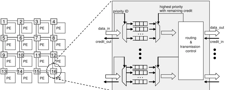
In this paper, we focus on one particular architectural construct that can be accurately described at a high level of abstraction such as TLM, namely a flow controller based on priority preemptive virtual channels. By assigning priorities to packets, and by allowing high priority packets to preempt the transfer of low priority ones, network contention scenarios become more predictable and do not require cycle-accurate models to be analysed. Fig. 1 shows the internal structure of a NoC router using such architecture. In each input port, a different FIFO buffer stores flits of packets arriving through different virtual channels (one for each priority level). The router assigns an output port for each incoming packet according to their destination. A credit-based approach [Bjerregaard and Sparso 2004] guarantees that data is only forwarded from a router to the next when there is enough buffer space to hold it.
At any time, a flit of a given packet will be sent through its respective output port if it has the highest priority among the packets being sent out through that port, and if it has credits (that is, buffer space on the respective buffer of the neighbouring node connected to that output port). If the highest priority packet cannot send data because it is blocked elsewhere in the network, the next highest priority packet can access the output link. The identified architecture is therefore able to provide guaranteed throughput (GT) to traffic of higher priority, and also provides means to calculate upper latency bounds to best-effort (BE) traffic, as the priority ordering clearly shows when a packet will be blocked. Its approach to guarantee throughput is more efficient than time-division multiplexing (TDM), as used in many NoC architectures such as [Goossens et al. 2005], where GT traffic gets a pre-assigned time-slot to use resources. Priority preemptive arbitration does not unnecessarily reserves resources, so low priority traffic can always use the NoC if there are no requests from GT traffic.
For the sake of simplicity, we describe below the behaviour of such a NoC router as a set of rules followed when forwarding a data packet from its input port (data_in in Fig. 1) to one of its output ports (data_out in Fig. 1), and therefore to the input port of the next router of the packet's route towards its destination. This is usually referred as the data-link layer behaviour of a NoC.
1. Each input port of a router can handle a number of virtual channels (VCs), and this number is defined at design time. We assume a common implementation of VCs, which defines a separate FIFO buffer to store the incoming flits of each VC at a router's input port, and avoids head-of-line blocking between flits of different VCs.
2. All flits of a packet use the same VC, and when a flit arrives to an input port of a router, the router can identify which VC the flit is using and therefore store it in the respective input buffer. We assume a common implementation of this feature, which is the encoding of the virtual channel ID on each flit (i.e. 2n additional control signals in the link, where n is the predefined number of supported virtual channels).
header and the counter is set to the packet length. If the counter is not zero, the counter is decremented every time a flit from the respective VC is forwarded through an output port to the subsequent router.
4. When a header flit is at the head of one of the VC buffers of a router, the router can identify which output port the flit should be forwarded to. This is defined by the network layer behaviour of the NoC, and we assume that the header will include the destination address which enables the router to decide which output port to use according to a deterministic routing algorithm (e.g. X-Y). Once this is done, the input VC is locked to the chosen output port once the header is processed and it remains locked until the packet is completely transmitted, so all flits following the header will be sent out through the same port (and therefore route).
5. An output port is aware of the availability of buffer space on each of the VCs of the input port at the other end of its link. This is usually referred as the NoC flow control mechanism, and we assume a credit-based implementation where the output port is initialised with credits for each VC that correspond to the respective buffer spaces available in the input port down the line. As flits are transferred over the VCs, the respective credits are decremented. Once the subsequent router forwards a flit to the next hop towards its destination over a given VC, it frees a buffer space and it uses control signals over the upstream link to replenish credits to same VC at the upstream output port. 6. An output port may be locked to multiple input virtual channels, because many packets
may need to be routed to the same neighbouring router. We assume that each output port will arbitrate contention by always sending out the flit of the input VC with the lowest ID that has credit (or highest, depending on priority assignment convention). Then, by assigning packets to VCs by matching their priorities to the VC IDs, it is possible to effectively achieve priority-preemptive arbitration of NoC links. Notice that the preemption happens at the granularity of a single flit, so a high priority packet will be given immediate access to the desired output port once it arrives at a router (assuming that its VC is not fully blocked down the line by previously transmitted packets of the same priority). Interleaving between packets of different priorities over a link will be handled by rule 2, as they will be assigned different VCs.
7. No assumptions are made on the arbitration of packets of the same priority arriving simultaneously to an output port, but for the sake of implementation simplicity we assume that once a packet is given access to the output port it will not be preempted by another packet of the same priority. Additional VC management functionality would be needed if this rule would not be enforced.
Fig. 1. Overview of the NoC architecture with detail of the router structure.
4. LIGHTWEIGHT MODEL OF THE NETWORK-ON-CHIP ARCHITECTURE
Unlike regular NoC simulation models, which are composites of routers, buffers, arbiters and links, the proposed model is a single monolithic interconnect component (Fig. 2). It is connected to all processing cores, which can be both sources and targets of inter-task communication packets. The interface between the processing cores and the proposed NoC simulation model is minimal, allowing every core to specify when a packet is released (i.e. ready to be carried by the NoC), what is its destination and at which level of priority it should be transferred. It also has a simple mechanism to notify each destination core when a packet has been received and is available in their local memory.
[image:7.612.130.513.81.234.2]The focus of this work is to determine, once a packet is released, how long it will take to be transferred by the NoC and be completely stored at the local memory of its destination core. The time elapsed between the packet release and its complete reception at the destination is referred as packet latency.
Fig. 2. General architecture of the proposed simulation model.
While structurally simple, the proposed simulation model must be able to accurately estimate the latency of each and every packet transfer. It must take into consideration the time the NoC takes to carry the packet as well as the time the packet is blocked by other packets with higher priority. Unlike some of the previous work, we consider blocking at all possible parts of the NoC architecture, from the core interface to all internal routers and links.
The core of our approach is the notion of interference suffered by a given packet. If a packet has the whole network to itself, estimating its latency is trivial as it becomes a function of the number of hops it must traverse over the NoC on the way to its destination, and the packet’s flit count. This is referred throughout the paper as the packet’s no-load latency. However, packet latency estimation becomes harder when multiple packets compete for the same NoC resources. This is a critical issue in the simulation of many NoC architectures, because the NoC must be simulated with a very small time granularity in order to accurately reflect the effects of resource arbitration. However, with priority arbitration it is possible to deterministically decide which
processing core send receive processing core send receive processing core send receive NoC interconnect
...
priority ID…
highest priority with remaining creditdata_in credit_out data_out credit_in
…
routing & transmission control priority ID…
highest priority with remaining credit…
routing & transmission
control
PE PE PE PE
PE PE PE PE
PE PE PE PE
PE PE PE PE
1 2 3 4
5 6 7 8
9 10 11 12
packet has precedence when acquiring a shared resource and which packet has to wait, i.e. which packet does not suffer interference and which does. If that relation is known, it is possible to quantify the amount of interference that each packet will suffer from other packets of higher priority (i.e. the time it has to wait for them to release the shared resources).
In order to reason more formally about our NoC, we rely on definitions regarding the behaviour of the NoC we are interested in analysing.
Definition 1 (Packet). A packet packeti = (srci, dsti, tri, priorityi, payloadi) defines the data
transmitted from one core to another in the NoC, where src and dst are the address of the packet’s source and destination over the NoC (e.g. 1 to 16 in Figure 1); tr is the release time of the packet; priority is an integer number denoting which packet has higher priority to acquire shared resources; and payload is an integer number denoting its flit count.
Definition 2 (Route). A route routei is a deterministic set of links (calculated using the XY routing
algorithm) that a packet needs to traverse to go from its src address to the dst address. XY routing is used here because it is a common choice in many NoC architectures, but this is not a requisite. The proposed approach can use any deterministic routing algorithm.
In the next paragraphs we show how interference analysis can be used to accelerate NoC simulation.
4.1 Interference analysis
In order to simulate the NoC’s packet latency, it is necessary analyse the possibility of
interference from higher priority packets over lower priority ones (following the classic textbook notion of interference as the ability to affect the temporal behaviour [Burns and Wellings 2009]). First, we define the conditions for interference between packets.
Definition 3 (Interference condition). A packet packeti can interfere with a packet packetj if and
only if priorityi > priorityj and routei routen.
Intuition: Consider two packets packetA and packetB, where the first packet has a higher priority.
By using priority preemptive arbitration of NoC links, it is straightforward to see that packetA can
influence the temporal behaviour of packetB but not the contrary. Still, this can only occur if the
routes followed the packets share at least one NoC link, otherwise no contention and therefore no interference is possible.
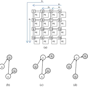
To reason about interference patterns across the whole NoC, we use a graph-based formulation. Therefore, we define an interference graph as a directed acyclic graph (DAG) that reflects the interference relations between all the packets being carried by a NoC, based on Definition 3. In such graph, each packet is represented as a node and each directed edge denotes an interference relation (see Fig. 3): if the routes of any two packets intersect, there will be an edge between their respective nodes, and the edge will be directed from the lowest to the highest priority packet. Based on a simple inspection of the interference graph, it is possible to decide whether at a particular point in time a packet is active (transmitting) or inactive (waiting for arbitration).
Definition 4 (Active packet). A packet packeti is said active at time t if and only if the node
representing it in the interference graph has no direct successors which are active, otherwise the packet is inactive.
In order to detail these ideas, consider the following example.
Example. Consider the scenario shown in Fig. 3.a, where at a time t = t’ the NoC is carrying the following packets: packet1 = (4, 1, tr1 < t’, p1, payload1); packet2 = (3, 2, tr2 < t’,
p2, payload2); packet3 = (5, 13, tr3 < t’, p3, payload3); and packet4 = (2, 13, tr4 < t’, p4, payload4).
The respective routes are shown as arrows in Fig. 3.a, making clear which NoC links
they use and thus whether they intersect. Assuming that p1 > p2 > p3 > p4, Fig. 3.b shows
the interference graph for that NoC at t = t’.
The interference graph in Fig. 3.b shows the nodes representing active packets in grey and the nodes representing inactive packets in white. Now, let us assume that at t = t’’ a new packet is released before packets 1 and 3 are delivered (which means that 2 and 4 have not finished either, as they are both inactive). The new packet, which appears as a dashed line in Fig. 3.a, is packet5
= (4, 3, t’’, p5, payload5), and p5 > p1. Fig. 3.c shows the updated interference graph at t = t’’.
Notice that due to Definition 4 the active status of some nodes had to be updated as well.
The completion time of a packet can be found by checking at which point in time it has been cumulatively active for the duration of its no-load latency (which is known in advance and does not depend on the state of the network). For example, let us assume that at time t = t’’’ packet 3 has been active long enough to be delivered to its destination core. At that point, the interference graph must be again updated (Fig. 3.d) and the latency of packet 3 can be easily calculated as t’’’
– tr3 i.e. its completion time minus its release time.
(a)
[image:9.612.160.443.333.611.2]
(b) (c) (d)
Fig. 3. Example traffic scenario (a) and respective interference graph at different points in time: (b) t = t’, (c) t = t’’, (d) t = t’’’.
4.2 Lightweight simulation component implementation
The model described in the previous subsection has been implemented as a simulation component, which encapsulates the behaviour of the complete NoC interconnect (as shown in Fig. 2). Such component was conceptually designed to interface with a variety of simulation frameworks, and relies on the assumptions that it should be able to:
PE PE PE PE
PE PE PE PE
PE PE PE PE
PE PE PE PE
1 2 3 4
5 6 7 8
9 10 11 12
13 14 15 16 p4
p1 p5 p2
p3
p2
p4 p3 p1
p2
p4 p3 p1
p5
p2
p4 p1
- Ask the simulation framework for the current time;
- Ask the simulation framework for a pure event1 at a specific time in the future; - Be notified when a specific processing core sends a packet into the NoC; - Deliver a packet to a specific destination core.
Internally, the simulation component must maintain the state of the NoC interconnect (i.e. interference graph) and perform the interference analysis to calculate the latency of each packet.
For performance reasons, we represented the state of the NoC as a list plist of all packets, sorted by their priority. Each entry includes the parameter tuple packeti of the respective packet
and additional information required by the proposed algorithm to calculate the delivery time of each packet:
- interferencei is the set of undelivered packets {packetj, packetk,…, packetn} whose route
shares at least one link with routei and whose priority is higher than priorityi
(Definition 1);
- activei is a boolean value that denotes whether packeti is active, as opposed to made
inactive by any active packetn interferencei;
- tai is the time packeti last became active;
- remainingpayloadi is the number of flits yet to be delivered at dsti.
Algorithm 1 describes the behaviour of the simulation component when a processing core sends a new packet into the NoC interconnect. It first initialises the parameters representing the new packet, then it searches over all other packets in the NoC for those that should be added to the new
packet’s interference set (based on route intersections and priority ordering). It then adds the new
entry to plist, keeping it sorted by packet priority.
Algorithm 1. Send Packet over Network-on-Chip
Input: packeti, list of all packets plist, current simulation time ctime.
Output: incremented plist.
remainingpayloadi = payloadi; activei = false; routei = routing(srci, dsti); for each packetn in plist {
if (routei routen ) {
if (priorityi < priorityn) {add packetn to interferencei;} else {add packeti to interferencen;}
} }
add (packeti, interferencei, activei, tai, remainingpayloadi) to plist; requestUpdate(ctime) ;
As described in the previous subsection, active packets are all those that have no active packets in their interference sets, so the typical case is that several packets will be active at the same time on a NoC as long as their routes do not intersect. When packets enter or exit the NoC, interference sets may change and therefore the active status and interference sets of all packets may need to be updated. In the proposed implementation, we use pure events to request updates as they are common feature in almost every event-based simulation framework. For example, an update is requested at the exact time that a packet enters the NoC (requestUpdate function, last statement in Algorithm 1).
Algorithm 2 describes the proposed update algorithm, used to discriminate which packets in plist are active, and to request additional updates for the time when active packets are likely to terminate.
Every time an update is triggered, the simulation component iterates over plist and updates the status of active and inactive packets according to changes on their interference set (i.e. a packet becomes inactive because a new packet is added to its interference set, or becomes active because
1 Pure events have a timestamp but no data attached to them. They can be used to activate simulation
all active packets in its interference set terminated or became inactive). Because plist is sorted by packet priorities, we can guarantee that when the algorithm iterates over a given entry of plist, all possible changes to the respective interference set have already been committed (because a packet can only suffer interference from higher priority packets).
When a packet becomes active, another update event is requested for the time it is likely to terminate (calculated according to the no-load latency of its remaining flits, denoted by the function noLoadLatency). If the packet is forced into inactivity before that time, that update event is cancelled and a new one will be scheduled when the packet is next activated.
Finally, updates must check if each active packet has already reached its destination by checking whether it was active for long enough to send all remaining flits. If that is the case, its entry is removed from plist, its latency is calculated and the packet is sent out to the target processing core.
Algorithm 2. Update Packet List
Input: list of all packets plist, current simulation time ctime. Output: updated plist, latency of packets delivered at current time. for each packeti in plist {
if (activei) {
remainingpayloadi = remainingpayloadi – sentFlits(ctime - tai); tai = ctime;
if (remainingpayloadi = 0) { remove packeti from plist; deliver packeti to destination; output latencyi = ctime – tri. }
for each packetn ininterferencei { if(activen) {activei = false;}
}
} else {
if (!activen for all packetn ininterferencei ){ activei = true;
tai = ctime;
requestUpdate(currenttime + noLoadLatency(remainingpayloadi));
}
} }
4.3 Discussion
The proposed approach can substantially reduce simulation time because it simulates the system only at the time instants when packets enter or exit the NoC, rather than every clock cycle or flit transmission. This reduces the computational overhead by reducing the number of updates to the simulation model. Rather that simulating every flit transferred over every link, the proposed approach is able to update the simulation model directly to the point that is relevant to the simulation user: when a packet is delivered to the destination (so its latency can be calculated). Compared to a cycle-accurate simulator, the potential speed up of the proposed model is directly proportional to the length of the packets and the hop count of their paths across the NoC (i.e. speed-up can be larger if the packets are larger and routes are longer).
packet is less than the hop count of its route, it will never fully occupy that route. The gaps left by such a packet can be used by another packet without causing any interference.
In such specific cases, the proposed model will assume interferences which could not occur in reality (e.g. packet A on its growing phase shares the last link of its route with the first link of the route of packet B, which is on its shrinking phase already). As a consequence, obtained latency figures may be higher than reality, and the overestimation will grow with the increase of the ratio between route hop count and packet flit count (i.e. the latency overestimation can be larger if routes are longer and packets are smaller).
Furthermore, overestimation of latency in high-priority packets may lead to underestimation of latency of low-priority packets that do not share links with them, due to the problem of indirect interference identified in [Shi and Burns 2008]. This happens because the overestimation of the latency of a high-priority packet may result on the excessive blocking of packets that could cause interference on a low-priority packet. Because of that excessive blocking, low-priority packets will not suffering the interference they would in the real system (or will suffer a reduced amount of it), and will therefore have potentially a lower latency.
In any case, the proposed model will never underestimate the latency of a packet if compared with a cycle-accurate model or a real system under the same interference scenario.
Finally, the proposed model does not guarantee that the worst-case latency of a packet will be found. The worst-case latency of a given packet will always depend on a specific interference pattern that arises from a specific packet release scenario. If such a scenario is actually simulated, then the proposed model will produce the worst-case latency for that packet (just as every other simulator), but there is currently no technique that can determine the exact scenario that leads to the worst-case packet latency in priority-arbitrated Networks-on-Chip. To find actual worst-case latency bounds, one must use the analytical models reviewed in Section 2, such as [Shi and Burns 2008].
5. EXPERIMENTAL RESULTS
In this section, we evaluate the simulation speed-up and the accuracy of the proposed model (LSI – lightweight simulation), with regard to a cycle-accurate model (CA) of the NoC architecture described in Section 3. According to Cai and Gajski’s taxonomy of transaction-level models [Cai and Gajski 2003], the proposed LSI model is classified as “Transaction model” (i.e. approximate -timed computation and approximate--timed communication) while the CA baseline is classified as
“Cycle-accurate communication model” (i.e. approximate-timed computation and cycle-accurate
communication). In such cases, the interconnect simulation dominates the simulation time of the processing elements, therefore motivating the research presented here.
For the following experiments, we customised the architecture described in Section 3 and assumed a 2D-mesh topology, 32-bit flit size, router input ports with eight virtual channels and two-position buffers each, XY routing, operating at 100 MHz. Three different configurations for each model were produced, a 4x4 mesh with 16 cores, a 6x6 mesh with 36 cores and a 10x10 mesh with 100 cores. We implemented all models using the same simulation framework, namely
UC Berkeley’s Ptolemy II [Eker et al. 2003], and we compared the performance of the proposed
LSI models against the corresponding CA baselines under a number of application-specific loads (i.e. testbenches).
To evaluate the simulation speed-up, we compare the simulation time of both models (i.e. for how long each of them executes, in wall-clock time) for a given target time (i.e. the length of application time that is simulated). Our goal is that LSI’s simulation time is much lower than CA’s simulation time, for the same target time.
Accuracy is then evaluated by calculating the difference between the packet latencies found using both models. Assuming the latency of CA as the correct one, our goal is to have the difference as small as possible.
models receive each packet at the exact same target time on their NoC interfaces, allowing us to focus on the accuracy of the behaviour of the proposed NoC model against a CA baseline, without influence of the behaviour of the processing elements. The only difference between the
testbenches is that CA’s network interface transfers packets flit-by-flit into the NoC simulator,
while in LSI it forwards to the simulator a single event that carries a timestamp and the data referred in 4.1 as the tuple packeti.
For the first set of experiments, we used as a benchmark the application presented in [Shi et al. 2010], which models the stereoscopic video processing, navigation and stability control subsystems of an autonomous vehicle (AV). The version of the application considered here comprehends 32 tasks and 38 inter-task fixed-priority communications. Two operating modes will be considered for the stereographic video processing and visual odometry subsystems:
high resolution (HR), with VGA frame resolution (640x420 pixels), 16-bit colour depth, 25 frames per second;
low resolution (LR), with QVGA frame resolution (320x240 pixels), same colour depth and frame rate.
Each application task has worst-case execution times ranging from 0.01 to 150 milliseconds. Inter-task communications are carried by packets with fixed-size payloads, the smallest with 512 flits and the largest 38400 flits (blocks of video frames in HR mode) or 9600 flits (likewise, in LR mode).
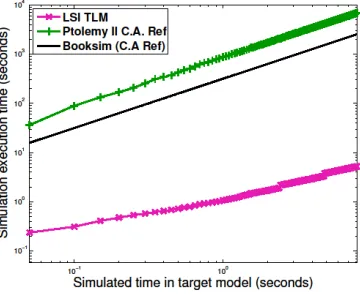
[image:13.612.224.404.455.602.2]Firstly, we need to establish that our baseline is in line with the state-of-the art in NoC simulations, so we compare the simulation times of both our CA and LSI models with a model of a NoC with priority-arbitrated virtual channels in Booksim 2 [Jiang et al. 2013], an open source cycle-accurate NoC simulator developed at Stanford University. We use AV LR application traces (i.e. timestamps of the release of packets) to subject the three models with the same load. Simulation times for the execution of 2 seconds of the AV application over each of the models configured with a 4x4 topology and a NoC frequency of 100 MHz are shown in Figure 4. Simulations were run on an 8-core Intel i7 PC running at 3.4 GHz. It can be seen that both cycle-accurate models have simulation times at the same order of magnitude, and Booksim 2 is approximately 3 times faster than our Ptolemy II CA model (partly because it is implemented in C++ and is compiled to native code, while Ptolemy II is interpreted by a Java Virtual Machine). Nonetheless, we can also see that our proposed LSI model is more than two orders of magnitude faster than both baselines.
Fig. 4. Simulation speed comparison between Booksim 2 and Ptolemy II-based CA and LSI models, for 4x4 NoC topology under the load the AV LR application.
received and processed, because the reply was statically timestamped and the request was delayed due to NoC congestion).
To avoid the shortcomings of trace-based simulation, we use application models to generate the computation and communication load to the simulation model, following the three-layer approach proposed in [Indrusiak et al. 2010] and [Ost et al. 2013]. That approach does not require statically obtained traces, and actually co-simulates an application with the platform in order to effectively release tasks and communication packets only when their pre-conditions are met (e.g. timer expired, precedence or dependencies are satisfied). In this case study, we assume that tasks communicate only after they finish execution, and that they always execute for their worst-case execution time. This is simply to ensure fairness in the comparison between LSI and CA simulators, and it is not a limitation of the proposed model. In regular usage, any task representation can be used, and packets can be injected to the NoC at any arbitrary time.
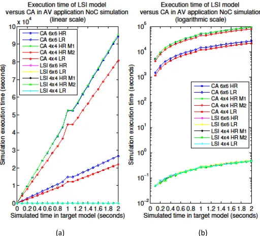
In Figure 5, we present an extensive comparison of the simulation times for the execution of 2 seconds of the AV application using 5 different experimental scenarios for each of CA and LSI models:
CA / LSI 6x6 HR: cycle accurate / proposed model of a 6x6 NoC running the high
resolution mode of AV
CA / LSI 6x6 LR: cycle accurate / proposed model of a 6x6 NoC running the low resolution mode of AV
CA / LSI 4x4 HR M1: cycle accurate / proposed model of a 4x4 NoC running the high resolution mode of AV using a non-optimised task mapping M1
CA / LSI 4x4 HR M1: cycle accurate / proposed model of a 4x4 NoC running the high resolution mode of AV using an optimised task mapping M2
CA / LSI 4x4 HR M1: cycle accurate / proposed model of a 4x4 NoC running the low resolution mode of AV
[image:14.612.177.433.433.665.2]Figure 5 (a) shows the simulation time in a linear scale, but since the speed up of the proposed models is so large – up to 5 orders of magnitude - it is impossible to see their simulation times (as they appear to be zero). Figure 5(b) displays the same data but uses a logarithmic scale over the Y axis, allowing for a better visualisation of the simulation times of the proposed models. Simulations were done on an Intel Core Duo PC at 3.02 GHz.
Fig. 5. Simulation speed comparison between CA and LSI models, for two topologies (4x4 and 6x6) under the load imposed by two configurations of the AV application (HR and LR), with
simulation time shown in (a) linear scale and (b) logarithm scale (in seconds)
Looking carefully at the plotted data, it is possible to see a number of scenarios with similar levels of performance:
Two of the cycle-accurate models executing the high resolution mode of the AV application are the slowest: CA 6x6 HR and CA 4x4 HR M1. This is because they simulate the load with the largest packets (due to the HR video frames) and the longest routes (because of the larger NoC or the non-optimised task mapping), and the simulation time of a CA model is directly proportional to the number of flits and the number of hops they go through (as discussed in subsection 4.3).
The cycle-accurate model executing the third type of HR load (CA 4x4 HR M1) has a slightly better level of simulation performance (clearly seen in Fig. 4.a), as the application mapping is better and results in smaller number of hops for each packet to go through.
The fastest CA models are those running the low resolution mode of the AV application, and the one modelling a 4x4 NoC is slightly faster due to the lower hop counts each packet goes through.
The performance of the proposed LSI models is nearly indistinguishable, regardless of the mode of the application or the size of the NoC. Such results provide evidence to back the claims made in subsection 4.3: the simulation speed of the proposed models increases only with the number of packets and the interference between them, and it does not increase with the size of the packets or the hop count of their routes.
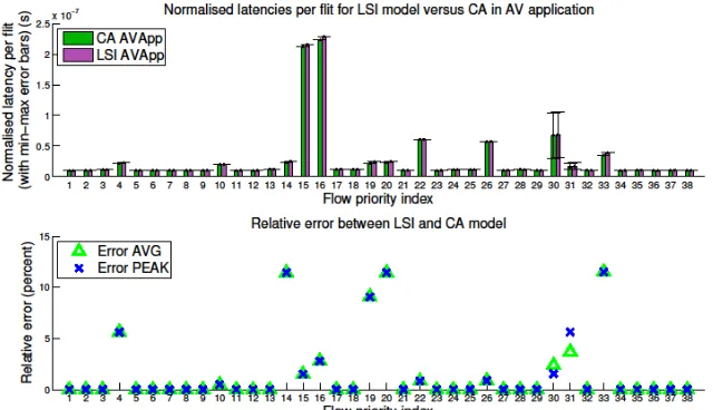
[image:15.612.147.467.502.686.2]The accuracy of the packet latency figures produced by the proposed model against the CA reference can be seen in Figure 6. The X axis shows the application inter-task communications, identified by their priority. The green and purple bars show, respectively for the CA reference and the proposed LSI model, the average latency values for all packets of each communication (obtained over 2 seconds of application execution). The latency values are normalised by each packet’s length in flits, so the plotted values are effectively the average latency per flit, in seconds. Each bar has whiskers to indicate the best-case and peak packet latencies of each inter-task communication. In the second plot of Figure 6, the percent error of the proposed model for the average and peak latency are shown, respectively, as a green triangle and a blue X. It can be see that in all cases the error is less than 13%. The overall aggregate error, which is the sum of all errors for each individual packet, divided by the number of simulated packets, is 1.68%. The error for best-case latency was not plotted because it is negligible or zero in all cases (as the best case latency is usually the case when packets do not suffer any congestion, therefore their latency is actually their no-load latency).
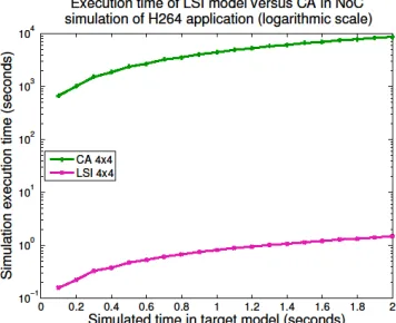
The second set of experiments uses the H264DL4x4 benchmark from the MCSL 1.1 benchmark suite [Liu et al. 2011], which accurately models the behaviour of a video decoding application and includes 76 distinct inter-task communications. Given the dataflow behaviour of the application, it can be seen as a simpler case study as the previous one (which is time-triggered), as it is easier to avoid contention over the NoC and thus avoid latency variability. We have run simulations with several different mappings of the application onto a 4x4 NoC, and have found that the proposed model accelerates simulation by 3-4 orders of magnitude in all of them, in line with the previous experiment. In many cases, given the limited contention on the network, we found that that the proposed model’s error is zero for most flows, and the highest average and peak latency error is in the order of 5%. For a more challenging comparison, we have hand-picked a task mapping that tries to maximise contention on the network (i.e. communicating tasks are always mapped to distinct cores to maximise over-the-network traffic). Albeit unrealistic for a real design, as it is highly inefficient, it can be used as a sort of stress test to evaluate the performance and accuracy of the proposed model. Figure 7 shows the comparison between CA and LSI simulation times for that specific mapping, and LSI still achieves nearly four orders of magnitude speed-up. However, as shown in Figure 8, in such case the proposed model’s error is more significant: up to 40% for the peak latency and also occasional underestimations, due to a difference in interference scenarios (because of packet dependencies) and the indirect interference issues discussed in section 4.3. Nonetheless, the overall aggregate error is only 2.62%.
[image:16.612.224.402.306.451.2]
Fig. 7. Simulation speed comparison between CA and LSI models for H.264DL benchmark mapped onto a 4x4 NoC, logarithm scale (in seconds).
Fig. 8. Normalised latency per inter-task communication obtained by CA and LSI models of a 4x4 NoC under the load of the H.264DL benchmark, and percent error of LSI against CA reference for
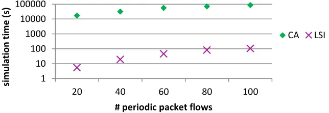
[image:16.612.109.502.506.679.2]In the third set of experiments, our goal was to evaluate the scalability of the proposed approach in terms of size and complexity of the application using the NoC as communication media. Firstly, we create a set of random packet flows that periodically send a packet with a random length to a random destination over a 4x4 NoC. We then simulated, in turn, 20, 40, 60, 80 and 100 of those flows for 2 seconds of target application time over CA and LSI models, and measured the host simulation time for each case. The results depicted in Figure 9 show that the scalability of our approach is similar to the CA model, but again with a speed-up that exceeds three orders of magnitude. The percent error of our model against CA for peak, average and best-case latencies was below 1% in all runs.
Fig. 9. Simulation time of CA and LSI models of a 4x4 NoC under synthetic loads with varying number of packets.
Moving further on the scalability analysis, we run a fourth series of experiments to investigate the effect of different packet and route lengths over larger networks. Experiments were performed on 10x10 NoCs, comparing the simulation performance and accuracy of the LSI models against the CA baseline under synthetic traffic of varying packet sizes and loads. New tasks were added every 0.1 seconds, representing an increasing load upon the NoC and a progressively more complex interference graph structure. Sources and destinations were selected randomly, and packets were injected by every active task every 0.1 seconds.
Figure 10 illustrates the performance the LSI and CA models deliver for a 10x10 NoC with packets varying in size between 20 to 100 flits (selected uniformly randomly on each packet injection). The LSI model delivers approximately 4.2 orders of magnitude performance improvement. In such a large NoC the longer mean route lengths contribute to an increased performance advantage for the LSI model, since the CA model incurs event load for every individual hop that every data flit crosses. Figure 10 also displays the performance in an identical 10x10 NoC but with reduced packet sizes (between 4 to 40 flits). The advantage for the LSI model is now 3.9 orders of magnitude, slightly less than before since less data is transmitted in each packet.
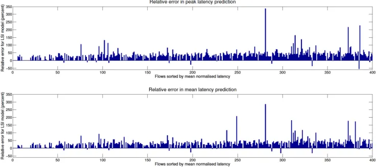
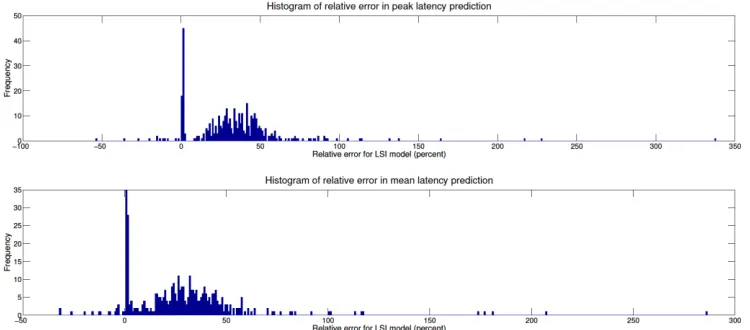
Considering the latency prediction accuracy of the first 10x10 NoC case, the normalised latencies per flow for both models are presented in Figure 11. The relative errors in peak and mean normalised latency, and a histogram of these are presented in Figures 12 and 13 respectively. Since the interference graphs are considerably more complicated, and the routes are now longer relative to the minimum packet size, the potential errors are now larger. However, the error histogram shows that the modal error for a flow is still around 1.5%, and the other relative errors are typically normally distributed around 25 - 30% overestimates. There is however a significant tail of outliers in both directions due to the issues discussed in subsection 4.3. The overall aggregate error for the case with packets between 20 and 100 flits is 28%, and 67% in the case with packets between 4 and 40.
1 10 100 1000 10000 100000
20 40 60 80 100
si
m
u
la
ti
o
n
t
im
e
(
s)
# periodic packet flows
Fig. 10. Simulation time of CA and LSI models of a 10x10 NoC under synthetic loads with varying packet sizes.
[image:18.612.116.495.314.475.2]Fig. 11. Normalised latency per inter-task communication obtained by CA and LSI models of a
10x10 NoC under synthetic loads with varying packet sizes.
[image:18.612.122.491.513.677.2]Fig. 13. Histogram of percent error of LSI against CA reference in the simulation of a 10x10 NoC
under synthetic loads with varying packet sizes.
6. CONCLUSIONS
In this article, we propose a fast and accurate simulation model for a specific Network-on-Chip architectural family, namely those with priority-preemptive arbitration. We have shown that such architecture can be modelled with a high level of accuracy at an abstraction level which is higher than clock cycle level or network flit level. By doing so, we were able to devise simulation models that only need to be updated at the points when packets enter or leave the Network-on-Chip, reducing substantially the computational effort, and therefore the time, to simulate such models when compared with cycle-accurate or flit-accurate models. We describe in detail the internal workings of the proposed model, including its formulation as an interference graph and the algorithms used by the model to handle new packets and packet deliveries.
Extensive experimental work was performed with three NoC topologies (4x4, 6x6 and 10x10) under the load of two realistic benchmarks, one of them with five different operation modes, and a large number of synthetic benchmarks. Experiments have shown that the proposed models simulate 3-5 orders of magnitude faster than an equivalent cycle-accurate model, for all benchmarks and NoC topologies. Results also show that unlike cycle-accurate models, the proposed model does not increase the simulation time when handling longer packets or packets with longer routes, which is an attractive feature when simulating larger networks.
Such a significant speed-up is due to the fact that the proposed simulation models take advantage of the predictable timing behaviour of the underlying NoC platform, and reduces significantly the number of simulation events that must be processed. While a cycle-accurate model has to handle simulation events to resolve the propagation of every packet flit over every NoC link, as well as all the link arbitration and flow control mechanisms at every NoC router, the proposed model only needs two simulation events per packet: when they enter and when they exit the NoC.
The significant speed-up provided by the proposed models comes at the expense of accuracy, but in most experiments the accuracy of the proposed model exceeded 70%. In situations when small packets are transmitted over large routes across the NoC, however, the proposed model can produce significant overestimates. Nonetheless, the accuracy figures reported here are either in line or better than the state-of the-art, while delivering speed-ups which are 1-5 orders of magnitude higher than those obtained by the state-of-the-art on abstract and TLM NoC simulators.
ACKNOWLEDGEMENTS
REFERENCES
Anant Agarwal. 2007. The Tile Processor: A 64-Core Multicore for Embedded Processing. In 11th Annual Workshop on High Performance Embedded Computing (HPEC). Lexington, Massachusetts, USA.
John Aynsley. 2009. TLM-2.0 Language Reference Manual. (2009).
Marco Bekooij et al. 2005. Dataflow Analysis for Real-Time Embedded Multiprocessor System Design. In Dynamic and Robust Streaming in and between Connected Consumer-Electronic Devices. 81–108.
T. Bjerregaard and J. Sparso. 2004. Virtual channel designs for guaranteeing bandwidth in asynchronous network-on-chip. In Norchip Conference. 269–272.
Evgeny Bolotin, Israel Cidon, Ran Ginosar, and Avinoam Kolodny. 2004. QNoC: QoS architecture and design process for network on chip. J. Syst. Archit. 50, 2-3 (February 2004), 105–128.
Alan Burns and Andy Wellings. 2009. Real-Time Systems and Programming Languages: : Ada, Real-Time Java and C/Real-Time POSIX 4th ed., Harlow: Addison Wesley.
L. Cai and D. Gajski. 2003. Transaction level modeling: an overview. In 1st IEEE/ACM/IFIP International Conference on Hardware/Software Codesign and System Synthesis, 2003. IEEE, 19– 24.
M. Eggenberger and M. Radetzki. 2013. Scalable parallel simulation of networks on chip. In 2013 Seventh IEEE/ACM International Symposium on Networks on Chip (NoCS). 1–8.
J. Eker et al. 2003. Taming heterogeneity - the Ptolemy approach. Proc. IEEE 91, 1 (2003), 127–144.
N. Genko et al. 2005. A novel approach for network on chip emulation. In IEEE Int Symposium on Circuits and Systems (ISCAS). 2365–2368 vol. 3.
K. Goossens, J. Dielissen, and A. Radulescu. 2005. AEthereal network on chip: concepts, architectures, and implementations. Des. Test Comput. IEEE 22, 5 (2005), 414–421.
Kris Heid, Haoyuan Ying, Christian Hochberger, and Klaus Hofmann. 2014. LatEst: Latency estimation and high speed evaluation for wormhole switched Networks-on-Chip. In Proc 9th Int Symposium on Reconfigurable Communication-centric Systems-on-Chip (ReCoSoC). IEEE.
Mohammad Hosseinabady and Jose L. Nunez-Yanez. 2010. SystemC Architectural Transaction Level Modelling for Large NoCs. In ECSI Forum on Specification and Design Languages (FDL).
Leandro Soares Indrusiak. 2014. End-to-end schedulability tests for multiprocessor embedded systems based on networks-on-chip with priority-preemptive arbitration. J. Syst. Archit. 60, 7 (August 2014), 553–561.
Leandro Soares Indrusiak et al. 2010. Evaluating the impact of communication latency on applications running over on-chip multiprocessing platforms: a layered approach. In 8th IEEE Int Conference on Industrial Informatics. Osaka.
Leandro Soares Indrusiak and Osmar Marchi dos Santos. 2011. Fast and Accurate Transaction-Level Model of a Wormhole Network-on-Chip with Priority Preemptive Virtual Channel Arbitration. In Proc Design Automation and Test in Europe (DATE). Grenoble, France: EDAA, 1089–1094.
Nan Jiang et al. 2013. A detailed and flexible cycle-accurate Network-on-Chip simulator. In 2014 IEEE International Symposium on Performance Analysis of Systems and Software (ISPASS). Los Alamitos, CA, USA: IEEE Computer Society, 86–96.
Kai-Li Lin, Chen-Kang Lo, and Ren-Song Tsay. 2010. Source-level timing annotation for fast and accurate TLM computation model generation. In Design Automation Conference (ASP-DAC), 2010 15th Asia and South Pacific. 235–240.
H. Kashif and H. Patel. 2014. Bounding buffer space requirements for real-time priority-aware networks. In Design Automation Conference (ASP-DAC), 2014 19th Asia and South Pacific. 113–118.
Abbas Eslami Kiasari, Axel Jantsch, and Zhonghai Lu. 2013. Mathematical Formalisms for Performance Evaluation of Networks-on-chip. ACM Comput Surv 45, 3 (July 2013), 38:1–38:41.
A. Kohler and M. Radetzki. 2009. A SystemC TLM2 model of communication in wormhole switched Networks-On-Chip. In Forum on Specification Design Languages, 2009. FDL 2009. 1–4.
Weichen Liu et al. 2011. A NoC Traffic Suite Based on Real Applications. In VLSI (ISVLSI), 2011 IEEE Computer Society Annual Symposium on. 66 –71.
Peter Marwedel. 2011. Embedded System Design 2nd ed., Springer.
Aline Mello, Leonel Tedesco, Ney Calazans, and Fernando Moraes. 2005. Virtual channels in networks on chip:
implementation and evaluation on hermes NoC. In 18th Annual Symposium on Integrated Circuits and Systems Design (SBCCI). Florianopolis, Brazil: ACM, 178–183.
Aline Mello, L. Copello Ost, F.G. Moraes, and Ney Calazans. 2004. Evaluation of Routing Algorithms on Mesh Based NoCs, Faculdade de Informatica - PUCRS.
H.W.M. van Moll, H. Corporaal, V. Reyes, and M. Boonen. 2009. Fast and accurate protocol specific bus modeling using TLM 2.0. In Design, Automation & Test in Europe Conference & Exhibition, 2009. DATE ’09. 316–319.
B. Nikolic, P. Meumeu Yomsi, and S.M. Petters. 2014. Worst-case communication delay analysis for many-cores using a Limited Migrative Model. In 2014 IEEE 20th International Conference on Embedded and Real-Time Computing Systems and Applications (RTCSA). 1–10.
Luciano Ost et al. 2013. Power-aware Dynamic Mapping Heuristics for NoC-based MPSoCs Using a Unified Model-based Approach. ACM Trans Embed Comput Syst 12, 3 (April 2013), 75:1–75:22.
Luciano Ost, Guilherme Guindani, Leandro Soares Indrusiak, Cezar Reinbrecht, Thiago Raupp, and Fernando Moraes. 2009. A high abstraction, high accuracy power estimation model for networks-on-chip. In Proceedings of the 22nd Annual Symposium on Integrated Circuits and System Design: Chip on the Dunes. Natal, Brazil: ACM, 1–6.
Yue Qian, Zhonghai Lu, and Wenhua Dou. 2009. Analysis of worst-case delay bounds for best-effort communication in wormhole networks on chip. In Proceedings of the 2009 3rd ACM/IEEE International Symposium on Networks-on-Chip. IEEE Computer Society, 44–53.
G. Schirner and R. Dömer. 2007. Result-Oriented Modeling—A Novel Technique for Fast and Accurate TLM. Comput.-Aided Des. Integr. Circuits Syst. IEEE Trans. On 26, 9 (2007), 1688–1699.
Gunar Schirner and Rainer Dömer. 2008. Quantitative analysis of the speed/accuracy trade-off in transaction level modeling. ACM Trans Embed Comput Syst 8, 1 (2008), 1–29.
Zheng Shi and A. Burns. 2008. Real-Time Communication Analysis for On-Chip Networks with Wormhole Switching. In ACM/IEEE Int Symposium on Networks-on-Chip (NOCS). 161–170.
Zheng Shi, Alan Burns, and Leandro Soares Indrusiak. 2010. Schedulability Analysis for Real Time On-Chip
Communication with Wormhole Switching. Int. J. Embed. Real-Time Commun. Syst. 1, 2 (June 2010), 1 – 22.
Emmanuel Viaud, François Pêcheux, and Alain Greiner. 2006. An efficient TLM/T modeling and simulation environment based on conservative parallel discrete event principles. In Proceedings of the conference on Design,