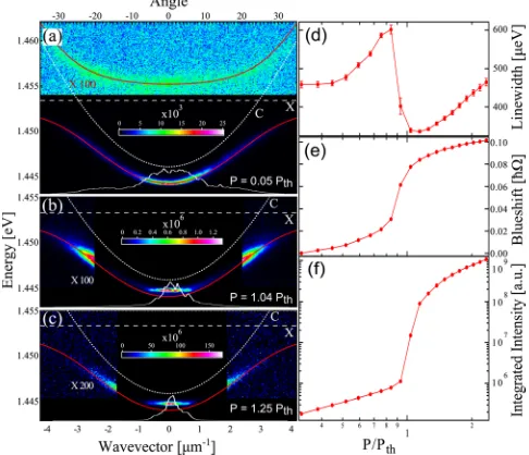
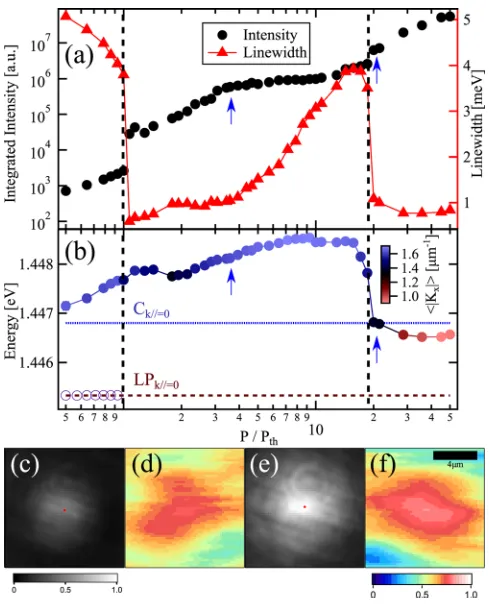
Polariton condensation in a strain-compensated planar microcavity with InGaAs quantum wells
Full text
Figure
Related documents
With regard to parental socio economic status, parents take up the responsibility to support their children regardless of their marital status and socio economic status
Green Paper on the Liberalisation of Telecommunications Infrastructure and Cable Television Networks – Part II - a Common Approach to the Provision of Infrastructure
It was hypothesised that providing information to families ( excluding clients) about schizophrenia, expressed emotion and ways in which each member can help ,
Shows a range of urea spreading rates, the target application rate and response based on spread CV using equation 1 response curve with four levels of field CV.. Grafton
The Commission understands the specific reasons that have led · Parliament to create a transitional regime applicable in the first legislature, following the entry into
Cette evolution a eu pour consequence d'accroitre la dependance alimentaire du Maroc pour des produits de grande consommation, comme les cereales et l'huile.. Akesbi.,
We may conclude,also, dbat the historian held liberal and Indefinite views about the future state fros his extremely sympathetic account of the Essenes, who denied the resurrection,
Analysis of the distribu- tions of molecular weight using the MULTISIG algorithm (Gillis et al. 2013 ) showed a relatively broad distribution for the alcell compared with the
