Local Ground-Based Plane Coordinates
Jeffrey Pickford 1 Peter Gibbings 1,2
1
Faculty of Engineering and Surveying
2
Australian Centre for Sustainable Catchments University of Southern Queensland
Toowoomba 4350 AUSTRALIA
ABSTRACT
When using RTK GPS it is convenient for surveyors to set their field controllers so they operate in local ground-based coordinates. Unfortunately this is not always done properly, and the errors associated with doing this are often not fully understood. This paper outlines the establishment of two different local ground-based coordinate systems: one based on the Tangent Plane; and the other based on the Transverse Mercator projection. The errors introduced by these projections are then analysed, and recommendations are made for their appropriate use. It was concluded that significant errors may be introduced by extending the coordinate systems any more than a few kilometres from the central project point, and height changes of as little as 20 metres may also be significant.
INTRODUCTION
The process of representing the Earth’s surface on any map projection causes distortions (Estopinal 1992). Despite these distortions, it is preferable from a surveyor’s perspective to use a map projection that presents the Earth as flat because this is what is shown on cadastral and engineering construction drawings. The flat representation of the Earth also allows the use of simple plane geometry and avoids the use of curvature corrections (Maling 1992).
Over large areas, regional map projections such as the Map Grid of Australia (MGA) provide a good approximation of the Earth’s surface for mapping purposes. On many surveys the adoption of, or connection to, MGA is either mandatory or necessary from economic and efficiency perspectives. But MGA is unsuitable for some purposes such as cadastral and engineering construction surveying. In these smaller sites, scale factors can cause problems because map grid distances are not the same as ground distances. As a consequence, local ground-based coordinate systems are often used over smaller areas to minimise map
projection distortion and to provide a method of obtaining coordinates at ground level, instead of the projection level (Wisconsin State Cartographers Office 2004). The result is that grid distances presented on a map or survey plan are essentially the same as ground distances measured in the field.
Figure 1 - Ground and MGA grid distance comparison
The line is at an elevation of 719m crossing the centre of MGA zone 56. It can be seen that the ground distance is considerably different from the MGA grid distance. This is representative of the difference between ground distances, which you would expect to measure in the field with a total station, and grid distances. Unfortunately it also represents the type of error that is regularly being made when presenting distances on cadastral and engineering survey plans. In this example, 400.207 would be the distance that ought to be shown on a cadastral survey plan since it represents a horizontal plane distance at ground level. However, this plane distance at ground level as it is referred to in cadastral surveying is not the same as a geodetic plane distance, and this seems to have caused some confusion.
This needs further explanation. For most practical applications, the geodetic plane distance and the grid distance can be assumed to be equal and in this example they are 400.000. Note that this is the distance that a coordinate routine in a calculator will give you [arc tan (∆E2+∆N2)] and this is not what you would expect to measure on the ground. Nor should this distance be shown on a cadastral survey plan. Grid and ground distances should not be confused with ellipsoidal distance, in this example, since the line crosses the central meridian of zone 56 and the line scale factor is therefore very close to 0.9996, the ellipsoidal distance 400/0.9996 = 400.160.
Recent technological advances have facilitated the proliferation of GPS receivers (particularly operating in the RTK mode) and digital storage controllers in surveying practices. Many practitioners would like their GPS controllers to provide them with ground distances, and most controllers will do this on an individual line basis. But not only is it desirable for GPS controllers to provide ground distances between points, it is also desirable to have a coordinate system that outputs ground distances for inclusion on engineering and cadastral plans. For example, a coordinate system in which grid distances equal ground distances is very useful for residential estate development as all survey and engineering computer aided plans can be on the same coordinate system. The coordinates can then be used to generate engineering designs and construction drawings, as well as cadastral survey plans.
The aim of this paper is to develop procedures for defining local ground-based coordinate systems and evaluate their limitations with respect to distances shown on survey plans. Discussion in this paper is limited to distances: angular distortions will not be addressed.
METHOD
A number of different projections can be used to create a local ground-based coordinate system and the errors associated with each will vary. The projections chosen for this paper are the Tangent Plane projection and a Transverse Mercator projection. Both local ground-based projections were constructed with the same point at the centre of the projection. Both projections can be defined entirely within commercially available software packages that have a suitable coordinate system editor. The Transverse Mercator and Tangent Plane projection methods were chosen because they were considered to be the two most common types of projections used in Australia for local ground-based surveys.
Local Ground-Based Coordinates from a Tangent Plane
Tangent plane projections are formed by bringing a flat plane into contact with a point of tangency on an ellipsoid and transferring features from the ellipsoid onto the plane (Iliffe 2002). To define the projection, the surveyor must specify the point of tangency and the orientation of the projection (Estopinal 1992). The tangent point becomes the centre of the projection and is usually chosen near the centre of the project site.
By default the meridian of the plane is usually set as true north in most of the latest computer aided drafting packages. However, the orientation of the tangent plane can be chosen to align with a map grid such as MGA, previous survey plans in the area, or some other convenient meridian. If aligning to MGA the rotation angle will be equal to the grid convergence, which can be obtained from relevant spreadsheets or manual calculation using Redfearn’s formula.
Finally, to avoid scale factors, this tangent plane is raised up to the average height of the project and thereby becomes a local ground-based coordinate system. It is also common to choose appropriate false Easting and Northing values of the central point to avoid confusion with other coordinate systems.
Local Ground-Based Coordinates from a Transverse Mercator Projection
The Transverse Mercator system projects geodetic coordinates from an ellipsoid onto a cylinder that has its axis perpendicular to the north-south axis of the ellipsoid. To minimise distortion, the ellipsoid is rotated to bring different meridians into contact with the cylinder for different areas around the globe. This is done in six degree increments to form the Universal Transverse Mercator zones (UTM). MGA is a UTM map projection based on the Geocentric Datum of Australia. The true origin for each zone is the intersection of the equator and the central meridian of the zones (Petrotechnical Open Standards Consortium 1997).
If the local ground-based coordinates are required to be aligned to the MGA meridian, the method involves selecting the appropriate MGA mapping zone that corresponds to the project site. The MGA projection is then modified to fit the local area by changing the central scale factor of the projection so that it matches the average height of the project site and also accounts for the point scale factor. The resultant local ground-based map projection might best be described as a modified UTM.
project height). The point scale factor can be obtained from spreadsheets or manual calculation using Redfearn’s formula. The datum scale factor is simply a ratio of the
geometric mean radius of curvature (average of radius of curvature in the meridian and prime vertical planes) of the ellipsoid at the project centre (R) divided by this radius plus the
ellipsoid height at that point (R+h). The combined scale factor is the MGA point scale factor multiplied by the datum scale factor. The MGA projection central scale factor now needs to be changed to a value equal to MGA central scale factor (0.9996) divided by the combined scale factor. A worked example for a project at the University of Southern Queensland (USQ) is provided for information and to further illustrate the process:
MGA Point Scale Factor (USQ) = 0.9997371584
Datum Scale Factor = R/(R+h) = 6365900 / (6365900+760.629) = 0.99988052937
Combined Scale Factor = MGA Point Scale Factor × Datum Scale Factor = 0.99961771917 Central Scale Factor = 0.9996 / Combined Scale Factor = 0.99998227405
Most software packages these days will do these calculations for you. As with the Tangent Plane, it is common to choose appropriate false Easting and Northing values of the central point of the project to avoid confusion with other coordinates.
Testing Distance Errors
The process of testing the distance errors associated with these local ground-based coordinate systems involved comparing the grid and ground distances along several lines at different orientations. Since the local ground-based coordinate systems were constructed so that these should be equal, any differences would represent errors introduced to the distances caused solely by assumptions made with the map projections. This comparison was carried out for both the Tangent Plane and Transverse Mercator versions of the local ground-based
coordinate systems. To give this some practical perspective, the error was then compared to expected distance measurement accuracies of a total station and RTK GPS. For this paper the primary site chosen for the establishment and testing of the local ground-based coordinate systems was in Toowoomba at an elevation of approximately 719 metres AHD.
The test involved generating a figure that consisted of a number of lines emanating from the central point of the project site. The lines starting from north and were generated at
increments of 10 degree separation continuing to a bearing of 350 degrees (refer to Figure 2). Lines were generated in 100 metre increments from 100m to 20km from the central point.
Testing Effects of Change in Height
When the local ground-based coordinate systems are defined, an assumption is made that all distances are measured at the average project height. Of course, this will not normally be the case on most surveys. Any change in height of measured lines above or below the average project height will result in some errors in reported distances – the grid distances will not exactly equal the ground distances. The error on reported distances due to height change in the line was calculated by comparing the difference between grid distance and the ground distance for several lines at various heights above and below the local ground-based map projection.
Again, to give the results some practical significance, the errors were related to the accuracy that might be expected in survey measurements. It is recognised that point and line measuring accuracy will vary due to many factors; for the purposes of this paper the following accuracies were adopted:
• RTK GPS measurement accuracy: 10mm + 1ppm
• Total Station measurement accuracy: 3mm + 2ppm
RESULTS AND DISCUSSION
Error Modelling
For this paper the isoline method of displaying errors in the projected distances was chosen because of its simplicity, ability to display a range of distortions and the ease with which it can be generated. Isolines are lines that connect points of equal value and can be assumed to be continuous: much like contour lines on elevation maps (Mulcahy & Clarke 2001).
Local Ground-Based Coordinates from a Tangent Plane Projection
Figure 3 – Distance error using tangent plane
As expected, errors are symmetrical around the central point of the projection, with direction not affecting the errors. At this test site, the RTK GPS measurement accuracy was not exceed up to approximately 19km in any direction from the central point of the projection and the total station measurement accuracy was not exceeded up to approximately 22.8km from the central point of the map projection (test figure lines were extended to determine this). It is acknowledged that a surveyor would not measure an individual distance of this magnitude, but they do provide some practical comparison to help interpret the results.
The error in reported distances due to the height of the measured line not being on the
[image:6.595.149.424.292.338.2]assumed average project height that was used in this local ground-based projection are shown in Table 1. These are the height variations past which the stated distance accuracies are exceeded. Note also that these heights are only valid for the test site, which had an elevation of 719 metres. Project sites at other elevations will have different values.
Table 1 – Distance error due to height - Plane
Accuracy Height above Height below
10mm + 1ppm 39.5m 39.5m
3mm + 2ppm 20.5m 20.5m
Logically, ground distances measured above the level of the local grid will be longer than portrayed in the local grid and ground distances measured below the level of the local grid will be shorter. This is due to the convergence of plumblines at points each end of the horizontal distance.
Local Ground-Based Coordinates from a Transverse Mercator Projection
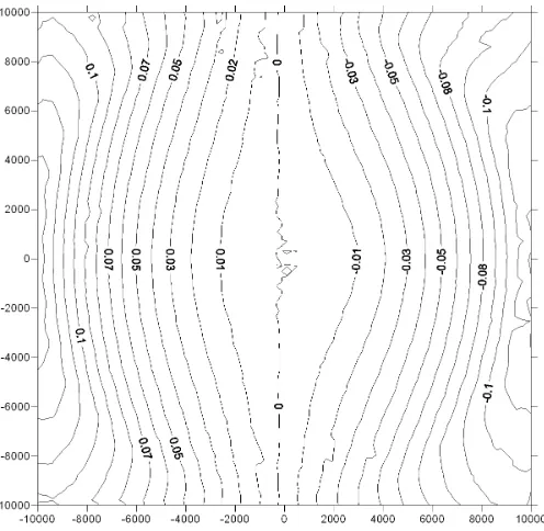
[image:6.595.174.422.473.715.2]The differences between the grid and ground distance shown in Figure 4 increase with distance from the central meridian of the site in this local ground-based coordinate system.
The differences are shown in metres and again the horizontal and vertical scales represent the distance from the central point in metres (10km in each direction in this case). The distance errors are dependent on the bearing of the line, which mirrors the behaviour of the point scale factor in the Transverse Mercator projections. Since this scale factor increases rapidly away from the central meridian of the site in an east/west direction, the Transverse Mercator
projection performs poorly in the east/west direction. The RTK GPS measurement accuracy is exceeded at about 3km east or west from the project central point. However, in a north/south direction, the RTK GPS measurement accuracy of the system was not exceeded within 50km of the central test point.
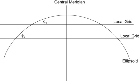
The Transverse Mercator projection at this test site produced ground distances on the eastern side that are longer than grid distances while those on the western side of the projection are shorter than grid distances. It is also noted that the distance errors are not exactly symmetrical about the project meridian. These effects are explained by the project meridian not coinciding with the UTM central meridian – refer to Figure 5. Assume the project site is located at the point where the deflection angle between the local grid and the ellipsoid is φ1 (refer to Figure
[image:7.595.169.412.363.505.2]5). The ellipsoidal surface (and ground surface) and the modified Transverse Mercator grid are diverging at a greater rate on the western side of the project site (to the left in Figure 5) than the eastern side of the project site (φ2 is greater than φ1 in Figure 5).
Figure 5 – Deflection between ellipsoid and Transverse Mercator
Figure 5 also demonstrates that the closer the project site is to the UTM central meridian the less the distance errors. The worst case will be when the project site is towards the edge of the UTM zones.
Similar to Table 1, Table 2 shows the error in reported distances due to the height of the measured line not being on the assumed average project height that was used in this local ground-based projection. These are the height variations at which the stated distance accuracies are exceeded.
Table 2 – Distance error due to height – Transverse Mercator
Accuracy Height above Height below
10mm + 1ppm 41.5m 37.5m
3mm + 2ppm 22.5m 18.5m
Validation of Local Ground-Based Projections
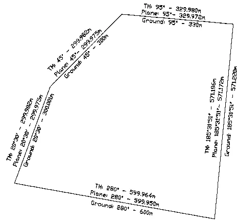
Toowoomba. A fictitious allotment was then constructed with all lines assumed to have been measured at the average project height that was used for establishing the local ground-based map projections (elevation of 719 metres in this case). This allotment was imported into both of these coordinate systems. The ground distances and the associated grid distances are shown in Figure 6.
Figure 6 – Test site validation of local ground-based map projections
All ground distances and bearings of the allotment at the project site were represented accurately using both the Transverse Mercator and the plane projection. In each case the dimensions that would be shown on a survey plan would be very similar to the ground distance that would be actually measured in the field.
Figure 7 – Example of failure of local ground-based map projections
It can be seen that there is now a large deterioration in the accuracy with which the local ground-based coordinate systems represent the boundaries of the allotment. The grid distances presented in both systems are presented at the Withcott project site height of 175m and the ground distances are shown as measured in the Toowoomba test site coordinate system at an elevation of 719m. It can be seen that the distances exceed the allowable measurement accuracy in all boundaries and consequently should not be used to represent ground distances on survey plans. A serious error in judgement has been committed in this case: a false
assumption has been made that all distances were measured at the average project height when in fact this was not the case.
This example illustrates that misusing local ground-based coordinate systems can lead to grossly inaccurate distances being shown on survey plans. The local ground-based coordinate systems can solve many of the problems mentioned in the introduction to this paper, but they must be used wisely or they will simply create additional problems of their own.
CONCLUSIONS
The most accurate method of taking distances from RTK GPS surveys for cadastral or engineering plans is to interrogate each line individually and calculate a horizontal ground distance. This is a trivial matter in most modern-day survey controllers and processing software. However, for some practical purposes it may be useful to also establish a local ground-based coordinate system. When this is done the surveyor needs to be aware that this process will introduce errors in the distances – distances from these local ground-based coordinate systems will not always be the same as the horizontal ground distances. The surveyor needs to decide if they are acceptable and within a ‘working difference’. In all cases it is recommended that suitable quality checks be applied including calculations on individual lines that might represent the ‘worst case scenarios’.
below the average project site, have varying affects on the accuracy of local ground-based coordinates systems depending on the projection method used.
The Transverse Mercator version of local ground-based projection far outperformed the Tangent Plane version in a south direction making it suitable for mapping narrow north-south sites such as pipelines or easements. In the test case used in this paper extending the project 50km in a north-south direction did not result in errors greater than normal measuring accuracy. However, the Tangent Plane performed better than the Transverse Mercator version in an east-west direction. In the test case about 3km in an east-west direction was the limit for the Transverse Mercator while about 20km in any direction was the limit for the Tangent Plane version. These issues considered, and the fact that local ground-based coordinate systems using a Tangent Plane are longitude-independent, probably makes them a better choice for a local ground-based projection for most general applications.
ACKNOWLEDGEMENTS
Special thanks is due to Associate Professor Kevin McDougall from USQ and Mr Garry Cislowski from NRW for reviewing this paper.
REFERENCES
Estopinal, S 1992, A Guide to Understanding Land Surveys, 2nd edn, New York.
Iliffe, J 2002, Datums and Map Projections for remote sensing, GIS and Surveying, Whittles Publishing, Latheronwheel, Caithness, Scotland.
Maling, DH 1992, Coordinate Systems and Map Projections, 2nd edn, Pergamon Press, Oxford, England.
Mulcahy, K & Clarke, K 2001, 'Symbolisation of Map Projection Distortion: A Review',
Cartography and Geographic Information Science, vol. 28, no. 3, pp. 167-81.
Petrotechnical Open Standards Consortium 1997, POSC Epicentre Version 2.2 Usage Guide, 10 May 2008,