Incremental Non-Equal Channel Angular Pressing – FE
Simulation
Andrzej Rosochowski
1, a)and Lech Olejnik
2, b)1Department of Design, Manufacture and Engineering Management, University of Strathclyde, 75 Montrose Street,
Glasgow G1 1XJ, United Kingdom
2Institute of Manufacturing Processes, Warsaw University of Technology, Narbutta 85, 02-524 Warsaw, Poland
a)Corresponding author: [email protected] b)
Abstract. Equal channel angular pressing is the most popular process of severe plastic deformation used to refine grain structure in metals in order to improve their properties. One of the features of severe plastic deformation is lack of change of billet's shape and dimensions. However, for practical reasons, departure from this pure definition might be useful. This paper considers a possibility of changing billet's cross section in the first pass of the incremental version of equal channel angular pressing from round to rectangular to avoid material loss when machining the initial billet. The process has been simulated using a finite element program Abaqus. This simulation showed feasibility of the process and provided information regarding tool geometry and required forces.
INTRODUCTION
Among severe plastic deformation (SPD) processes, used to refine grain structure in metals in order to improve their properties, equal channel angular pressing (ECAP) is the most popular one because of the relative simplicity of tool design (two intersecting channels) and tool kinematics (static die and translating punch) [1]. The traditional definition of SPD requires that the shape and dimensions of the billet's cross section remain unchanged. This means that a round bar remains round and a square bare remains square after being processed by ECAP. In practice, a small reduction of the output cross section is used in order to be able to repeat the process using the same input channel without machining the billet. This is related to the fact that the billet processed by ECAP with two identical channels has a larger cross section than the initial billet due to a clearance between the initial billet and the input channel and springback of the billet after coming out from the output channel. A more substantial change of the output cross section would be a departure from classical ECAP and, therefore, is rare [2-4]; such a process is referred to as non-equal channel angular pressing (NECAP). Reduction of the output cross section in NECAP can bring some benefits such as higher strain, finer grain size, increased texture and normal anisotropy. However, a radical change of billet's cross section makes further processing by ECAP/NECAP problematic because a new set of tools, with different channel and punch geometry, is needed.
to be equal to the diagonal of a square. This results in π/2-1=0.57 volume of the round bar machined out. In order to be able to use the most popular and inexpensive round bars as the initial material but to reduce/avoid their machining, an incremental NECAP process is proposed, where a round bar is converted into a square/rectangular bar with nearly identical cross section area. Thus the process is non-equal channel in terms of shape of the cross sections of the two channels but equal channel in the sense of the area of these cross sections. The second pass would use a square/rectangular cross section bar produced in the first pass of the process. A similar change of cross section from round to square was used in ECAP-Conform [11] but it was not due to simple shear because the change of cross section occurred earlier, in a rectangular grove of the feeding drum. Since changing the shape of cross section from circular to square/rectangular, combined with shear deformation, has probably never been tried, it seems to be appropriate that before engaging substantial resources in tool making, and possibly doing it several times to find the best tool geometry, a finite element (FE) simulation is carried out. Results of this simulation are presented in this paper.
FE MODEL
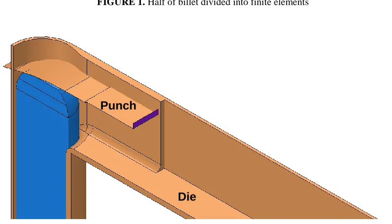
[image:2.612.107.505.414.642.2]The FE software used to simulate the incremental NECAP (I-NECAP) process was Abaqus/Explicit. The initial billet was in the form of a single 155 mm long round bar with 21.7 mm diameter and rounded top end (Fig. 1). Only half of the billet was modelled due to symmetry. It was divided into nearly 19,000 linear hexahedral elements of type C3D8R. Since these are reduced integration elements they are prone to hourglassing, which leads to billet elements ignoring contact conditions and penetrating the tools. To avoid this sort of effect, hourglass control of the stiffness type was employed. The billet material was described as an elastic plastic von Mises/Huber material with Young's modulus of 105,000 MPa and Poisson's ratio equal 0.37. The flow curve used was σ=318(0.02+ε)^0.27 MPa. The material parameters were chosen arbitrarily but were assumed to be close to those representing commercial purity titanium deformed at elevated temperature and medium strain rate.
FIGURE 1. Half of billet divided into finite elements
FIGURE 2. Shell parts representing die and punch
Tools were modelled as 3D discrete rigid shell bodies. Figure 2 displays a die and a punch and additionally the billet in its initial position. The die is made of two intersecting (at 90°) channels, a round vertical channel with 22
mm diameter and a horizontal channel 18.9 mm wide. The horizontal channel becomes wider towards the exit of the die to reduce friction between billet and die. Any sharp edges in the die are rounded to facilitate material flow. The thickness of billet in the horizontal channel depends on the bottom position of the reciprocating punch (assumed to be 19.4 mm). In the simulation, only punch face is required and it can penetrate die walls. The punch face is sloped and rounded and it has a material relief step towards the billet exit. A feeding device pushing billet upwards is not shown in Fig. 2. It was simply a flat horizontal shell in contact with bottom end of the billet.
Interaction between billet and die was modelled using a penalty contact method while interactions billet/punch and billet/pusher used a kinematic contact method. Friction was simulated using a Coulomb law, with friction coefficient of 0.05. No friction stress limit was assumed for such a low coefficient.
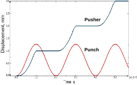
[image:3.612.171.458.329.509.2]Load/boundary conditions used in the simulation included stationary die and moving punch and pusher. The incremental nature of the process requires that the reciprocating movement of the punch and incremental feeding movement of the pusher are synchronised. The sine wave parameters for the punch were defined trough the amplitude periodic function of Abaqus: circular frequency 1000 Hz, coefficient A=0 and coefficient B=1. The vertical component of punch velocity was 2000 mm/s. Kinematics of the pusher was defined by the amplitude tabular function of Abaqus using a time vs. amplitude table [0-0; 0.0001-0; 0.0009-1; 0.001-0; 0.0021-0; etc]. The vertical velocity of the pusher was 2222.22. mm/s. Figure 3 shows the movements of the punch and the pusher in the first few cycles of the process resulting from these parameters. According to this figure, the punch double amplitude was 1.273 mm while the feeding stroke was 1mm. High tool velocity was applied to increase the time increment in the simulation and in result reduce calculation time. This sort of scaling can be used provided the material model is not strain rate sensitive and the inertia effects are small. Another boundary condition used was constraining material flow in the symmetry plane of the billet in the direction perpendicular to that plane.
FIGURE 3. Displacement of punch and pusher in first three cycles
FE SIMULATION RESULTS
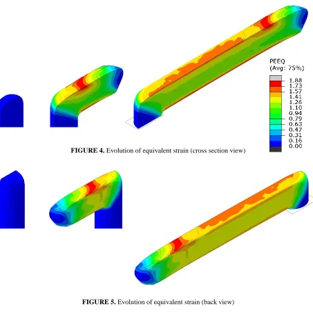
Only first pass of the process was simulated. Among many different types of results, geometry of the billet is interesting because it describes end effects, distortions and bending, which influence material utilisation and amount of work required to prepare billet for the next pass. Distribution of equivalent plastic strain is also valuable information, which gives an idea about homogeneity of the resulting grain size and properties. Figures 4, 5 and 6 provide this sort of information using different views and cuts. All these figures use the same scale of equivalent strain, as shown in Fig. 4, which helps compare the results. It is apparent that strain distribution is not uniform and, excluding end effects, it varies between 1.1 and 1.7. The core of the billet is strained to about 1.15, which is a theoretical value for ECAP with the channel angle of 90°. Higher strain of about 1.35 is in the surrounding material, which reaches the sides of the billet. The highest value of strain is in the thin layers on the top and bottom surfaces of the billet. This type of strain distribution is probably due to friction causing additional deformation.
Pusher
FIGURE 4. Evolution of equivalent strain (cross section view)
FIGURE 5. Evolution of equivalent strain (back view)
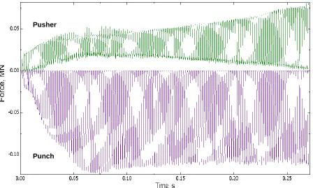
Another result of practical interest is the history of reaction forces on the punch and the pusher. Figure 7 shows how these forces oscillate due to incremental character of the process. The envelope of the punch force indicates two stages, the initial growth to a maximum value and then a small drop and constant value illustrating a steady-state stage. The force on pusher is generally smaller than the force on punch because part of the punch force is taken by the die. The history of the pusher force is mainly affected by friction force in the input channel, which is gradually reduced due to reduction of the billet length in this channel. Thus, after the initial increase of this force following a similar increase of the punch force, the steady state phase manifests itself as increasing amplitude of the pusher force. Eventually, the upper envelope of the pusher force, representing its billet supporting function during deformation, reaches its maximum value of approximately 2/3 of the punch force. The reason for this behaviour towards the end of the process is that friction in the input channel does not help supporting billet anymore. The bottom envelope of the pusher force is also due to friction, which does not let the billet move freely and pusher to relax even if the force on punch is zero. The feeding action of the pusher results in a tiny force nearly indistinguishable from the bottom envelope of the graph.
FIGURE 7. Evolution of forces on punch and pusher
CONCLUSIONS
3D FE model implemented in Abaqus/Explicit enabled efficient process simulation, without numerical problems such as locally distorted elements penetrating tools. FE simulation results have shed some light on what can be expected when an I-NECAP process is performed, when a round cross section bar is converted into a square/rectangular cross section bar by simple shear, which characterises the ECAP family of SPD processes. First of all, the proposed tool geometry and tool kinematics have proven to be feasible for this sort of conversion, providing smooth material flow leading to required billet geometry. Some bending of the billet, especially its front end, may cause problems with inserting it in the same die again. This will require an additional straightening operation to be carried out. As in all 3D ECAP processes, strain distribution is non-uniform, which is due to end effects and the influence of friction. It is expected that billet rotations between consecutive passes will reduce this inhomogeneity. The process forces follow the pattern known for I-ECAP. In the first stage, the punch force reaches
Pusher
its maximum value and then drops a little. The same is for the billet supporting force carried by the pusher but at a lower level. During the steady state, the punch force is constant, while the pusher supporting force climes up due to less help from friction in the input channel. If the feeding mechanism was based on billet clamping, which enables processing infinite length billets, the length of friction contact between billet and input channel would be constant and accordingly the force required to support billet during deformation would be constant. It is worth noticing that in any case the billet supporting force is not greater than 2/3 of the punch force. The feeding force is negligible.
ACKNOWLEDGMENTS
This research was financially supported by the Engineering and Physical Sciences Research Council, United Kingdom, [Grant no. EP/K503861/1], within the framework of Impact Accelerated Account - University of Strathclyde 2012.
REFERENCES
1. V. M. Segal, V. A. Reznikov, A. E. Drobyshevskiy and V. I. Kopylov, Russian Metallurgy 1, 99-105 (1981). 2. M. V. Markushev, V. N. Sloboda and O. A. Kaibyshev: Russian Patent No. 2146571 (2000)
3. L. S. Toth, R. Lapovok, A. Hasania and C. Gub, Scripta Materialia 61, 1121-1124 (2009).
4. F. Ferenshteh-Saniee, M. Asgari, M. Barati and S. M. Pezeshki, Transactions of Nonferrous Metals Society of China 24, 3274-3284 (2104).
5. A. Rosochowski, European Patent EP 1 861 211 (2012) 6. A. Rosochowski, U.S. Patent No. 8,631,673 (2014)
7. A. Rosochowski and L. Olejnik, “FEM simulation of incremental shear”, in: 10th International Conference on Material Forming, Esaform 2007, AIP Conference Proceedings 907, edited by E. Cueto and F. Chinesta (American Institute of Physics, Melville, NY, 2007), pp. 653-658.
8. A. Rosochowski and L. Olejnik and M. Richert, Materials Science Forum 584-586, 139-144 (2008). 9. A. Rosochowski and L. Olejnik, “Incremental ECAP of thick continuous plates - machine and initial
experiments”, in: 6th International Conference on Nanomaterials by Severe Plastic Deformation, NanoSPD6, IOP Conf. Series: Materials Science and Engineering 63 (2014) 012010.
10. A. Rosochowski, M. Rosochowska, L. Olejnik and B. Verlinden, Steel Research International 81/9, 470-473 (2010).